Meaning
Geometric dimensioning and tolerancing provides a uniform language for defining the physical geometry of mechanical parts on engineering drawings and digital data models. Adoption of asme y14.5 ensures that designers and manufacturers share a common understanding of part requirements across different facilities and regions. It provides a mathematical basis for defining the shape and orientation of features using a set of standardized symbols and rules.
The standard governs the interpretation of tolerances but does not dictate the specific manufacturing processes used to achieve them. It stops being the primary reference when the requirements move into the realm of material chemistry or surface coating thickness. Consistent application of these rules eliminates the confusion caused by differing internal drafting standards.
Geometric Definition
Precise descriptions of part features are achieved in asme y14.5 through the use of feature control frames and datum reference frames. These frames specify the allowable variation for characteristics like flatness, circularity and parallelism. Engineers select datums based on how the part will be constrained during its final assembly.
This selection ensures that the measurement process mimics the actual use of the part in the field. When a feature is defined by its position, the standard allows for a cylindrical tolerance zone which provides more usable area than a square coordinate zone. Such an expanded zone permits a higher yield during the production phase without affecting the assembly of the mating components.
Design Intent
Communication of functional requirements from the design office to the production floor relies on the logic found within asme y14.5. It enables the use of material condition modifiers that provide bonus tolerance when a hole is larger or a pin is smaller than its maximum size limit. This mechanism reduces the scrap rate by accepting parts that still function perfectly despite minor size deviations.
Production teams use these rules to adjust their machining offsets and tool paths to stay within the specified boundaries. A clear definition of the part geometry allows for better coordination between suppliers and original equipment manufacturers. The standard acts as a contract that defines the acceptable limits of physical variation for every part produced.
Inspection Protocol
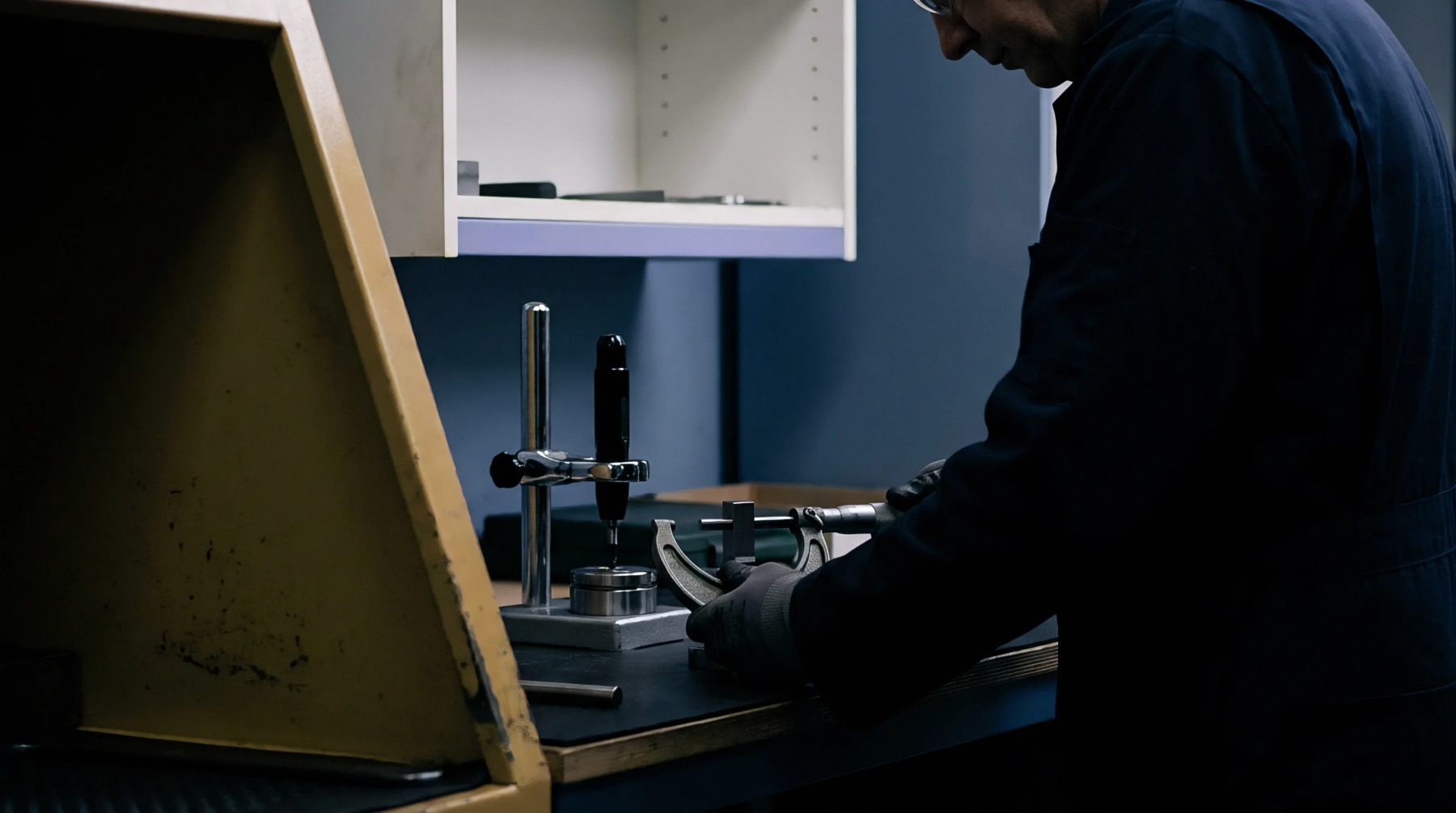
Measurement of features according to asme y14.5 requires a clear understanding of the datum hierarchy and the simulated mating envelopes. Inspectors use coordinate measuring machines to verify that the manufactured parts stay within the geometric limits. These programs must be written to follow the specific alignment instructions provided by the datum reference frame.
Verification of a part against this standard confirms that the demonstrated rate of production meets the capability required by the design. It prevents the shipment of components that might fit into a fixture but fail in the final assembly due to incorrect orientation. The final inspection report provides a defensible record that the physical part matches the engineering intent.
Accurate data collection supports the transition from prototype to full scale manufacturing by identifying areas where the process needs more control. This verification step is the last barrier before parts are shipped to the customer.