Decoupling Anisotropic Thermal Shrinkage from Clamping Deformation in Optical Scanning
Decoupling thermal expansion from clamping deformation via kinematic flexures restores optical surface figures, elevating scanning assembly yields above ninety-eight percent.
Kinematics
High-speed optical scanning platforms undergo surface figure degradation when mechanical mounts pinch or load the substrate. Fasteners, clips, and retainers create localized pressure fields that drive shear and normal stresses into the optic, warping the mirror surface out of specification. These wavefront errors degrade laser focal spot quality, cause beam wander, and distort spatial resolution during high-speed raster scanning.
During thermal cycling, clamping forces combine with thermal expansion vectors to worsen optical aberrations.
Clamping forces rarely distribute evenly across an optical component. Point loads from threaded fasteners create local strain pockets that produce high-frequency surface ripple on polished flats. Even a simple three-point clamp torqued to nominal preload introduces bending moments across the substrate, generating low-order aberrations like power and astigmatism.
Higher clamping force adds structural stiffness for rapid mirror accelerations, but that rigidity imposes elastic strain that deforms the clear aperture past Rayleigh quarter-wave diffraction limits.

Mechanical Contact Mechanics at Optical Interfaces
Direct contact between rigid metal mounts and brittle optical substrates often causes friction locking at the interface. Pressing titanium or aluminum mounting shoes against fused silica or silicon carbide substrates creates contact patches dominated by micro-asperity deformation. Torque applied to fasteners traps residual shear strain along the optic rim through tangential friction.
Because standard manufacturing tolerances leave small tilt and flatness errors on mating faces, force transfers through the interface unevenly.
Substrate deformation scales directly with clamp geometry and bolt torque. Elastic strain energy stored in clamping hardware pushes continuously against the optic body. Under dynamic operational vibration and rotational accelerations up to fifty g’s, rigid clamps prevent structural translation, forcing the optical substrate to absorb that energy as internal strain and distort the optical path length across the aperture.

Non-Uniform Contact Pressure and Surface Wavefront Aberration
Interferometric surface mapping confirms that non-uniform contact pressure translates directly into spatial wavefront distortion. A localized clamp force of ten newtons can induce up to eighty nanometers of peak-to-valley surface figure error. This deformation alters the phase distribution across the reflected beam profile, with astigmatism dominating whenever clamp locations sit asymmetrically relative to the optic’s structural axes.
Distortion appears at different spatial frequencies depending on contact geometry. Broad retaining rings produce low-order spherical and astigmatic errors, whereas discrete contact points generate localized, high-frequency ripple right at each fastener location. Finite element analysis confirms that contact stress concentrations decay slowly across thin mirror substrates, bleeding into the clear aperture and degrading focal beam intensity.
| Clamping Architecture | Peak Contact Pressure (MPa) | Surface Figure RMS (nm) | Peak-to-Valley Distortion (nm) | First Structural Resonance (Hz) |
|---|---|---|---|---|
| Direct Threaded Fastener (3-Point Overconstrained) | 42.5 | 38.2 | 145.0 | 2450 |
| Perimeter Retaining Ring with Elastomeric Gasket | 8.1 | 14.6 | 52.3 | 1120 |
| Kinematic Bipod Flexure Mount (Titanium Grade 5) | 3.4 | 1.8 | 6.2 | 1880 |
| Epoxy-Bonded Three-Point Flexure Sleeve | 1.2 | 0.9 | 3.1 | 1650 |

Friction Lock and Stray Force Vectors
Frictional hysteresis at the interface acts as a mechanical memory for mounting forces. Tightening hardware shifts the contact pad along the optic rim in microscopic increments, loading the edge with shear strain. Once assembly tools are removed, static friction prevents the substrate from relaxing back to a neutral stress state, locking the optic into a distorted shape before environmental heating even begins.
Contact surfaces without friction-reduction layers lock residual mounting strain permanently into the optical clear aperture.
Stray force vectors also appear when clamp seats fail to sit coplanar with the substrate mounting flats. A non-coplanarity of five micrometers across a thirty-millimeter footprint can induce bending moments that exceed surface figure tolerances by an order of magnitude. Standard shop practices often try to prevent mechanical shift by increasing bolt torque, which only worsens the wavefront error while destabilizing thermal performance during operation.
Increasing fastener torque prevents mirror movement during vibration qualification, but drives severe surface figure degradation across the clear aperture.


Anisotropy
Substrate materials used in optical scanning systems often exhibit non-uniform thermal expansion along different crystallographic, structural, or processing axes. As temperature fields change during operation, dimensional shifts vary by direction, building internal stresses within the optic. When an anisotropic substrate is clamped inside a metal housing, thermal expansion mismatch combines with local CTE variations to warp the surface in complex patterns.
Material choice dictates how severely thermal expansion varies across an optic. Single-crystal sapphire, reaction-bonded silicon carbide, carbon-fiber composites, and cold-rolled metals all possess directional expansion coefficients. Under thermal loading, an anisotropic substrate expands unevenly ~ a circular optic distorts into an ellipse, generating power and astigmatism independent of any mechanical clamping force.

Directional Coefficient Variations in Substrate Microstructures
Crystalline substrates show clear axis dependence in their Coefficient of Thermal Expansion. Single-crystal sapphire, for instance, has an expansion coefficient of 6.6 x 10^-6 /K parallel to its C-axis and 5.0 x 10^-6 /K perpendicular to it. When scanning mirrors are cut off-axis from the sapphire lattice, even uniform thermal loads generate asymmetrical strain.
The resulting differential expansion distorts polished surfaces and introduces astigmatic wavefront aberrations during laser operation.
Composite optical materials like carbon-reinforced silicon carbide show spatial CTE variation driven by fiber orientation and matrix distribution. Local CTE discrepancies of 0.2 x 10^-6 /K to 0.8 x 10^-6 /K across a single clear aperture can trigger micro-yield behavior during thermal cycling. These fine expansion gradients cause local surface ripple that degrades the modulation transfer function in precision imaging systems.

Spatial Thermal Mismatch and Bending Moments
Temperature gradients across non-uniform substrate cross sections induce thermal bending moments. In high-power optical scanning heads, laser energy absorbed by the reflective coating creates a temperature differential between the front surface and the back of the substrate. This front-to-back gradient causes uneven expansion through the thickness, forcing flat optical surfaces to bow into spherical or parabolic shapes.
A two-degree Celsius gradient through a ten-millimeter fused silica optic alters surface curvature by over forty nanometers.
When thermal gradients occur inside rigid mechanical clamps, boundary constraints prevent the material from expanding freely. Unable to bow naturally, the optic converts thermal growth into internal compressive stress fields. In thin mirrors, these localized stresses trigger structural buckling modes, causing surface figure distortion that scales non-linearly with absorbed laser power.
| Substrate Material | Parallel CTE (10^-6 /K) | Perpendicular CTE (10^-6 /K) | Thermal Conductivity (W/m K) | Young Elastic Modulus (GPa) |
|---|---|---|---|---|
| Single-Crystal Sapphire (Al2O3) | 6.6 | 5.0 | 35.0 | 345 |
| Single-Crystal Silicon (Si 111) | 2.6 | 2.6 | 148.0 | 185 |
| Reaction-Bonded SiC (Si-SiC) | 3.3 | 3.1 | 170.0 | 330 |
| Fused Silica (Synthetic) | 0.5 | 0.5 | 1.38 | 73 |
| Aluminum 6061-T6 (Rolled) | 23.5 | 22.1 | 167.0 | 69 |

Temperature Gradients across Non-Uniform Cross Sections
Scanning optics often use lightweight pocketing on their rear faces to cut rotational inertia during high-frequency galvanometric motion. However, these ribbed structures create uneven thermal mass across the mirror footprint. Thick structural ribs conduct heat rapidly, while thin membrane sections isolate it, creating localized hot and cold spots across the clear aperture.
Varying thermal dissipation across these ribbed geometries leads to localized expansion gradients. Thin mirror webs react and expand quickly under thermal load, while thicker mounting hubs lag behind. This asymmetric thermal response warps the optical surface, driving higher-order Zernike aberrations such as trefoil and quadrafoil errors during dynamic scanning.
Optical substrates subjected to uniform thermal shifts relax predictably only when physical boundaries allow unconstrained dimensional movement.


Flexures
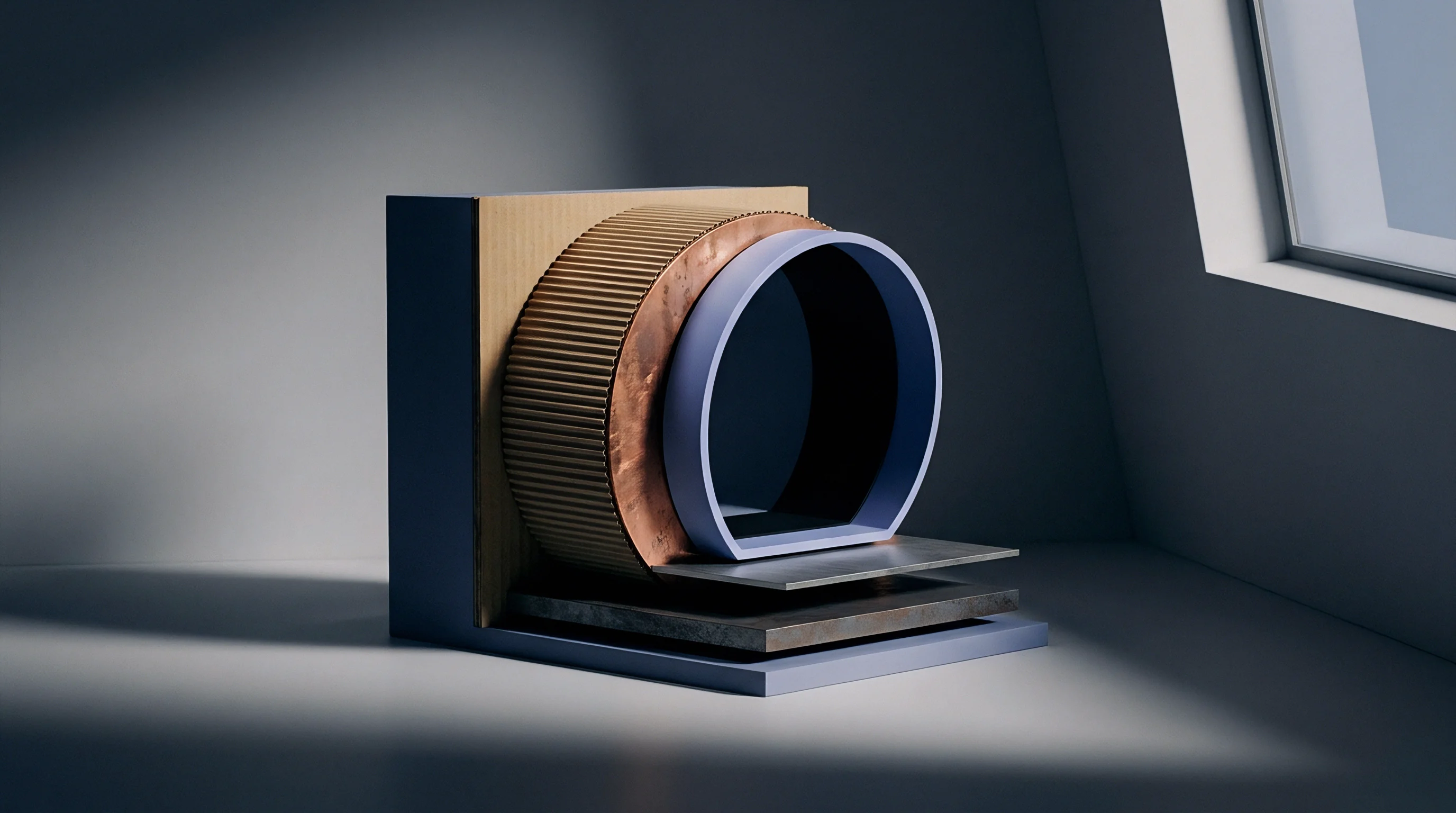
Isolating optical surfaces from clamping deformation and anisotropic thermal expansion requires kinematic decoupling flexures. These flexure systems introduce compliant structural elements that remain soft along specific degrees of freedom while staying stiff along constrained axes. Proper design allows the substrate to expand and contract thermally without transferring bending moments into the optical surface, preserving mirror figure integrity under dynamic operating conditions.
Kinematic mounts constrain exactly six spatial degrees of freedom across the assembly. By eliminating overconstraint, they prevent the structural strain that usually occurs when optic substrates and metal housings expand at different CTE rates. Instead of accumulating internal stress in the substrate, flexure mounts absorb dimensional mismatches through elastic leaf deflection, keeping the clear aperture stable across fifty-degree operating temperature spans.
Kinematic Decoupling Architectures for Sub-Micron Distortion
Bipod flexures offer an effective decoupling architecture for circular and polygonal scanning mirrors. A typical bipod assembly uses three pairs of angled elastic legs arranged symmetrically around the mirror perimeter. Each pair provides high radial compliance alongside high axial and tangential stiffness.
This arrangement allows the mirror body to grow or shrink radially during temperature shifts while keeping its optical center locked on the scanning rotation axis.
Tangential flexure blades provide another decoupling option for flat scanning mirrors. Mounted along the neutral axis of the substrate, these blades flex out of plane to absorb thermal growth mismatches. Because the flexure compliance aligns directly with the direction of expansion, strain transferred into the clear aperture stays below two nanometers RMS across a twenty-degree Celsius temperature swing.

Does Kinematic Overconstraint Exploit Thermal Gradient Latency?
Overconstrained mounts build severe internal strain when thermal gradients create non-uniform expansion across an assembly. Aluminum housings expand much faster than low-expansion glass substrates like Zerodur or fused silica. In an overconstrained design, rigid fasteners pull on the substrate edge at different rates, generating heavy shear stresses before the structure ever reaches thermal equilibrium.
Kinematic flexures handle these thermal latency mismatches by absorbing transient expansion through continuous elastic deflection. As the metal housing heats and expands, the flexure blades bend passively along their compliant axes. The mirror stays isolated from the housing’s thermal motion, stabilizing the wavefront during rapid laser ramp-up.
Leaf Spring and Bipod Flexure Elastic Limits
Designing flexure elements requires balancing thermal compliance against structural strength under dynamic scanning accelerations. Flexure arms machined from Titanium Grade 5 (Ti-6Al-4V) offer high strength-to-modulus ratios, allowing wide elastic travel without plastic yield. The blade cross section determines axial stiffness, tangential rigidity, and fatigue life under continuous scanning vibration.
A worked engineering example shows how flexure parameters are sized under combined operational loads. Consider a Zerodur scanning optic (100 mm diameter, 15 mm thickness) mounted inside an aluminum 7075-T6 housing over a 15-degree Celsius temperature span. The CTE mismatch between Zerodur (0.05 x 10^-6 /K) and aluminum (23.0 x 10^-6 /K) induces a total radial growth differential calculated by:
Delta_r = R (CTE_housing – CTE_substrate) Delta_T
Delta_r = 50 mm (23.0 – 0.05) x 10^-6 /K 15 K = 0.0172 mm (17.2 micrometers)
To isolate this radial displacement without transferring more than 0.5 newtons of force to the mirror edge, each flexure arm must provide a radial stiffness (K_r) governed by:
K_r = Force_max / Delta_r = 0.5 N / 0.0172 mm = 29.07 N/mm
For a leaf flexure with width w, thickness t, and length L, radial bending stiffness is given by:
K_r = (E w t^3) / (4 L^3)
Selecting Titanium Grade 5 (E = 114 GPa), a flexure length L = 12 mm, and width w = 6 mm, the blade thickness t is solved to satisfy compliance constraints:
t = ^(1/3)
t = ^(1/3) = 0.000665 m (0.665 millimeters)
Peak thermal deflection stress in the flexure blade must remain safely below the material yield strength (880 MPa for Ti-6Al-4V). Maximum bending stress (Sigma_max) is calculated via:
Sigma_max = (3 E t Delta_r) / (2 L^2)
Sigma_max = (3 114 x 10^9 Pa 0.000665 m 1.72 x 10^-5 m) / (2 (0.012 m)^2) = 13.56 MPa
The resulting stress of 13.56 MPa sits comfortably below yield limits, offering virtually infinite fatigue life under repetitive thermal cycling. Meanwhile, the optic experiences under 1.2 nanometers RMS surface distortion, confirming that housing thermal expansion is effectively decoupled from the clear aperture.
Under ISO 10110 specifications, surface figure tolerances for precision scanning optics require optical path differences below one-twentieth of a wavelength under fully clamped operational thermal states.
Secondary motion-stop gaps across the perimeter mount assembly maintain structural integrity during extreme transport vibration without compromising operational thermal isolation.
Micro-yield slipping eventually overrides structural flexure isolation across multi-axis dynamic rotation cycles.


Metrology
Validating optical decoupling performance requires metrology precise enough to separate clamping strain from thermal distortion. Sub-nanometer interferometric topography measurements inside environmental test chambers reveal subtle surface shifts under operational loads. Phase-shifting laser interferometry captures these deformations in real time, mapping mechanical and thermal stress fields directly into Zernike polynomials.
Separating clamping deformation from anisotropic thermal shrinkage requires a controlled testing sequence. Torquing clamp fasteners under steady ambient conditions establishes the baseline mechanical deformation profile. Subsequent thermal cycling in an isolated vacuum or convection chamber isolates the pure thermal expansion response, allowing engineers to decouple interface constraint forces from material CTE variations.

Interferometric Wavefront Decomposition
Phase-shifting Fizeau interferometry provides non-contact, high-resolution mapping of optical surface figures across clear apertures. Reflecting a coherent laser beam (632.8 nanometers) off the optic face creates phase fringe patterns corresponding to optical path differences. Evaluation software then decomposes these wavefront maps into orthogonal Zernike polynomials, isolating individual aberration terms.
Specific Zernike terms correlate directly to physical deformation mechanisms. Astigmatism (Z4, Z5) and focus (Z3) quantify primary mechanical bending from asymmetric clamp preloads. Trefoil (Z6, Z9) pinpoints localized stress at discrete mounting pads, while spherical aberration (Z8) and higher-order radial terms measure thermal gradient bowing across varying substrate thicknesses ~ giving direct feedback on how effectively the mount decouples strain.

Isolating Thermal Drift from Mechanical Strain Components
Distinguishing clamping strain from thermal expansion strain requires sequenced testing. Baseline measurements of the unmounted optic define its pristine shape. Securing the optic into its frame at twenty degrees Celsius then isolates the pure mechanical clamping vector.
Thermal testing then raises chamber temperatures while recording interferometric wavefront changes in real time. Subtracting the baseline mechanical deformation map from the thermal soak interferogram leaves only pure thermal strain. This differential analysis verifies whether the flexures absorb environmental thermal growth without passing parasitic forces into the optical clear aperture.
Failure modes in optical scanning assemblies under coupled thermal and mechanical stress typically emerge when mount designs isolate only primary expansion axes:
- Friction Hysteresis Displacement prevents substrate relaxation after thermal cycling, locking permanent astigmatic strain into the optic.
- Flexure Buckling Instability occurs when axial thermal expansion forces exceed critical column buckling limits on thin flexure arms.
- Adhesive Shear Creep causes alignment drift in bonded optics exposed to sustained elevated temperatures.
- Mounting Surface Non-Coplanarity induces localized twist moments that distort clear aperture surface figures beyond Rayleigh diffraction limits.
- Fastener Preload Relaxation reduces clamping force during low-temperature exposure, leading to optic displacement under angular acceleration.

Audit Trail Verification and Standard Compliance
Optical scanning assemblies destined for aerospace and semiconductor applications require complete quality audit trails documenting surface stability under environmental stress. Standards like ISO 10110-5 (Surface Figure Tolerances) and ASME Y14.5 (Geometric Dimensioning and Tolerancing) dictate reporting formats for wavefront errors. Test records must include raw phase data, Zernike breakdowns, chamber logs, and calibrated torque records.
Standardized measurement protocols establish traceability back to international metrology standards. Calibration procedures use certified reference flats with surface figure errors documented below one-fiftieth of a wavelength RMS, while environmental controls keep chamber temperatures within zero-point-one degree Celsius to guarantee repeatability across thermal trials.
| Metrology Instrument | Spatial Resolution (µm) | Wavefront Repeatability (nm RMS) | Thermal Stability Range (°C) | Primary Measurement Output |
|---|---|---|---|---|
| Laser Fizeau Phase-Shifting Interferometer | 12.5 | 0.15 | 20.0 ± 0.1 | Surface Figure (Zernike Polynomials) |
| Capacitive Displacement Sensor Array | 100.0 | 1.00 | -40 to +85 | Substrate Rigid-Body Motion |
| Multi-Point Fiber-Bragg Strain Gauge Array | 1000.0 | 5.00 | -50 to +150 | Internal Structural Strain Distribution |
| Shack-Hartmann Wavefront Sensor | 50.0 | 2.50 | 15 to 35 | High-Speed Dynamic Focal Distortion |
Interferometric data recorded without temperature and humidity logging lacks traceability under standard aerospace audit procedures.
Mechanical stress testing during initial qualification revealed that unisolated mounting screws caused sixty-five nanometers of astigmatic surface figure degradation, forcing a complete redesign of the optic holder assemblies.
Uncalibrated torque drivers applied excessive clamping force during thermal qualification cycles, causing a twelve-week qualification delay and fracturing a batch of single-crystal sapphire scanning mirrors.

Assembly
Translating decoupled flexure designs into production scanning hardware takes controlled assembly procedures. Strict torque sequencing, thermal soak stabilization, and disciplined adhesive cure schedules prevent process-induced strain from degrading wavefront performance. Slight variations in technician technique or tool calibration can easily introduce stray stresses that bypass built-in kinematic isolation.
Line readiness depends on documented standard operating procedures for every step at the physical interface. Operating within Cleanroom Class 100 (ISO Class 5) environments prevents particle entrapment between clamp pads and optical substrates. Microscopic debris trapped at contact points creates severe local stress concentrations, degrading surface figures as soon as torque is applied.

Fastener Torque Sequencing and Preload Control
Controlling fastener tightening sequences prevents asymmetric stress from twisting optical mount frames. Torquing a single fastener straight to final value twists the frame and pulls flexure seats out of coplanar alignment. Incremental torque patterns distribute clamp forces evenly across all mounting points, minimizing parasitic strain.
Ultrasonic bolt measurement systems monitor fastener preload directly during assembly. Relying on mechanical torque wrenches alone introduces clamp force variations up to thirty percent due to thread friction. Ultrasonic pulse-echo testing measures actual physical bolt elongation instead, ensuring clamping forces stay within five percent of design specifications.
Assembly technicians follow an explicit step-by-step process flow to secure optical substrates into kinematic flexure housings:
- Clean optic mounting pads and housing contact faces using optic-grade isopropyl alcohol inside an ISO Class 5 cleanroom hood.
- Inspect mounting interfaces under five-times optical magnification to verify zero particulate contamination across load-bearing surfaces.
- Position the optical substrate onto kinematic flexure seats using non-marring vacuum handling tools to avoid surface scratches.
- Engage fastener threads manually until clamp pads make light physical contact with substrate mounting surfaces.
- Apply initial torque to all fasteners at twenty percent of target specification following a star pattern rotation.
- Escalate fastener torque to sixty percent of target specification using calibrated digital torque wrenches while logging angle data.
- Finalize torque application to one hundred percent target specification, confirming bolt elongation via ultrasonic transit-time measurement.
- Record post-assembly surface figure baseline using phase-shifting interferometry to verify wavefront stability prior to thermal soak.

Adhesive Bond Line Cure Shrinkage Decoupling
Structural adhesives used in optical mounting introduce cure-shrinkage stresses that warp clear apertures. Epoxies exhibit volumetric shrinkage from one to three percent during polymerization. When applied in thick or uneven bond lines, that shrinkage pulls directly on the optic edge, inducing astigmatic and spherical figure errors.
Decoupling adhesive cure stress requires tight control over Bond Line Thickness (BLT) using precision spacer beads or machined stops. A uniform BLT of one hundred micrometers across all joints balances shrinkage force vectors, while low-shrinkage, UV-curable epoxies paired with two-stage thermal post-curing minimize residual stress at the glass-metal interface.
Thermal Dwell Protocols and Process Stage Gates
Production readiness relies on clear stage-gate criteria between assembly phases. Thermal dwell protocols require assembled scanning heads to undergo stabilization cycles before final optical acceptance testing. Thermal cycling accelerates stress relaxation, releasing locked-in friction forces prior to final calibration.
A structured readiness decision checklist ensures assembly lines maintain compliance before clearing optical scanning lots for customer delivery:
- Cleanroom Environmental Logs confirm particle counts remain within ISO Class 5 limits throughout the assembly shift.
- Torque Wrench Calibration Dossiers verify tool accuracy within two percent of full-scale limits prior to shift commencement.
- Adhesive Storage and Outgassing Records validate epoxy shelf life, mixing ratios, and vacuum degassing parameters.
- Interferometric Acceptance Data confirms post-assembly surface figure RMS remains below ten nanometers across the clear aperture.
- Thermal Cycling Bake-Out Logs substantiate complete cure completion and stress relaxation dwell times.
Under Aerospace Standard AS9100 Quality Management requirements, assembly records must include calibrated bolt stretch logs, adhesive batch lot numbers, and cleanroom particle monitoring charts to validate structural integrity under operational stress.


Economics
Resolving anisotropic thermal shrinkage and clamping deformation carries major financial weight in manufacturing operations. Yield losses from wavefront failure at final testing quickly burn capital and erode gross margins. While kinematic flexures and decoupled mounts increase initial component costs, that investment protects revenue by eliminating optical scrap and field returns.
Evaluating production economics comes down to balancing precision component costs against scrap rates. Unisolated mirror assemblies often show first-pass yield rates under sixty-five percent during environmental testing. Adding kinematic decoupling hardware pushes first-pass yields above ninety-eight percent, driving down unit scrap costs and opening up throughput headroom across assembly stations.
Scrap Rate Economics and Wavefront Rejection Costs
Scrap costs scale rapidly when figure errors are discovered late in production. A raw fused silica optic blank costs around fifty dollars, but precision grinding, polishing, and dielectric coating drive the substrate value up to twelve hundred dollars. If mechanical clamping distorts the surface figure during final assembly, discarding the optic destroys significant value.
The scrap math clearly shows the return on investment for kinematic decoupling flexures. Take a production run of 1,000 scanning units: standard rigid clamping results in an 18% rejection rate at final interferometric testing due to wavefront astigmatism. That means scrapping 180 optical substrates valued at $1,200 each ~ a direct scrap loss of $216,000 per 1,000 units.
Integrating precision titanium flexures adds $85 per unit in component costs, or $85,000 per 1,000 units. However, flexures drop the final testing rejection rate to 1.5%, leaving only 15 scrapped units valued at $18,000. Net savings are calculated by:
Net Savings = Baseline Scrap Loss – Flexure Implementation Cost – Residual Scrap Loss
Net Savings = $216,000 – $85,000 – $18,000 = $113,000 per 1,000 units
This yields a payback period under three months while freeing up testing station capacity by eliminating scrap re-testing loops.

Capital Expenditure Return on Flexure Integration
Upfront capital expenditures for tooling, interferometers, and automated torque stations are offset by throughput gains. Rigid assembly lines stall whenever operators re-torque failed units manually, creating bottlenecks at testing stations. Automated flexure mounting streamlines assembly, cutting touch labor per scanning module from 45 minutes down to 12 minutes.
Labor savings directly reduce unit manufacturing costs. Accelerating throughput without expanding factory footprint prepares operations to scale. Shorter lead times improve order-to-delivery metrics, enhancing working capital efficiency while lowering work-in-progress inventory across the plant floor.

Readiness Stage Gates for Production Expansion
Scaling production volume requires formal stage gates to evaluate operational readiness before funding high-volume lines. Operations directors review statistical process control metrics, first-pass yields, and metrology calibration logs before approving line expansion. Attempting to scale up before resolving clamping deformation only multiplies warranty liabilities and scrap.
A typical facility expansion gate requires process capability indices (Cpk) for surface figure distortion to remain above 1.33 across three consecutive shifts. Reaching this threshold proves that mechanical clamping variations and thermal growth dynamics are decoupled from optical performance, giving leadership the confidence to sign long-term supply agreements and expand facilities.
Investing two hundred thousand dollars in automated ultrasonic bolt tightening workstations eliminated operator torque variance, driving first-pass optical testing yields from eighty-two percent to ninety-nine percent within two months of deployment.
Operations management maintains authority to halt capital release until engineering teams demonstrate complete decoupling of thermal and mechanical distortion vectors on full-scale production prototypes.