Free State Metrology Fundamentals for Flexible Molded Components
Free state metrology requires defining gravitational orientation and contact loads to stop baseline deflection from corrupting quality inspection data.


Gravity
A molded elastomeric seal or thin-walled thermoplastic duct resting unconstrained on a coordinate measuring table sags under its own dead weight. Coordinate measuring machines equipped with touch probes record deflections caused by probe trigger force rather than true tool geometry. Optical sensors avoid probe force deflection yet capture the body deformed by gravitational sag.
Free state dimensioning under ASME Y14.5 defines the condition of a part subjected only to the force of gravity. ISO 10579 addresses the same physical state under the non-rigid parts designation. Both standards recognize that flexible moldings change shape when removed from their tooling cavities, cooling fixtures, or shipping trays.
Engineering drawings specify free state dimensions with the modifier circle-F. This modifier informs quality control that geometric tolerances apply without restraining forces, or it accompanies a restraining note defining exact clamping parameters. When an engineering drawing omits restraint specifications, inspection occurs in the detached, resting state. A ninety-durometer polyurethane boot holds its shape under gravity.
A forty-durometer silicone diaphragm collapses entirely. Inspecting that diaphragm without specified restraint produces non-repeatable dimensional data across differing measuring stations.
Variations in part orientation relative to the earth coordinate system generate contradictory rejection logs across receiving docks. A curved automotive weatherstrip measured with its concave profile facing upward sags inward, narrowing its lip gap. The same weatherstrip inverted on the inspection table splays outward under identical gravitational mass, expanding the lip gap beyond upper specification limits.
Tooling corrections ordered from unsupported free state coordinate runs systematically destroy tool steel, chasing gravitational deflection rather than mold cavity error.
A sixty-durometer ethylene propylene diene monomer profile resting unsupported on an optical table deflects downward under gravitational load by three times its allowable profile tolerance.
Quality agreements resolve this dispute by fixing the orientation of the component during measurement, establishing datum targets, and defining maximum permissible gravitational distortion before rejection occurs. When drawings lack these parameters, suppliers measure parts oriented to minimize sag, while receiving inspectors drop parts onto surface plates arbitrarily. The resulting measurement dispute stops production lots, ties up working capital in quarantine areas, and forces emergency waivers on parts that fit functional assemblies perfectly.
The cost of resolving ambiguous free state drawing callouts shifts directly to the buyer when assembly lines halt over non-functional dimensional variances.

Fixture

Restraint Mechanics and Contact Forces
Restrained condition inspection simulates functional installation by applying specified holding forces before probe sweeps begin. ASME Y14.5 Section 5 allows drawing callouts to define the sequence, magnitude, and contact surface for restraining clamps. Clamping flexible molded parts presents two failure modes: insufficient clamping force allows part float during non-contact laser scanning, while excessive clamping force induces localized material displacement that distorts adjacent features.
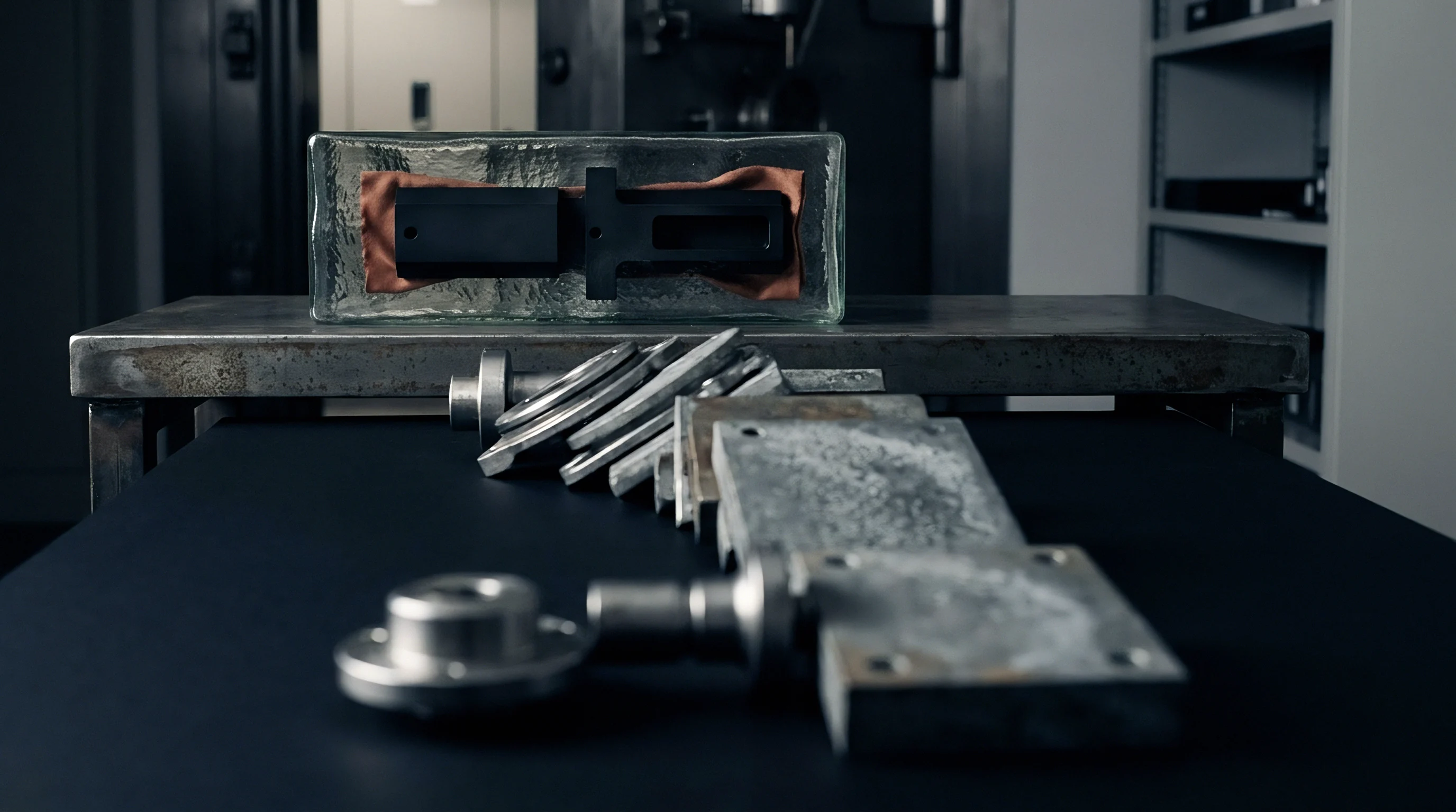
Mechanical toggles apply uncontrolled point forces that crush soft elastomers. Pneumatic actuators with precision regulators maintain predictable contact loads across repeat setups. Fixture nests constructed from machined polyoxymethylene or aluminum cradle the non-rigid molding, supporting datum features along their functional engagement planes.
Contact pressure during clamping must stay below the compressive yield limit of the polymer at ambient temperatures. Fixtures utilizing vacuum hold-down plates distribute restraining forces across continuous profiles, eliminating the localized pinch zones typical of mechanical fingers.

Datum Target Placement on Compliant Profiles
Rigid body mechanics assume three points define a primary plane, two points define a secondary line, and one point establishes an origin. Compliant moldings violate rigid body assumptions: three datum points leave flexible spans between targets unsupported, permitting thermal or gravitational oil-canning between stations. Datum target callouts for flexible parts specify area targets or high-density target arrays rather than spherical points.
| Material Designation | Hardness Range | Recommended Clamping Method | Nominal Contact Pressure | Gauge Repeatability Band |
|---|---|---|---|---|
| Silicone LSR | 30 to 50 Shore A | Full profile vacuum nest | 15 to 30 kPa | 0.08 mm to 0.14 mm |
| EPDM Extruded/Molded | 55 to 70 Shore A | Pneumatic pad with urethane tip | 45 to 70 kPa | 0.05 mm to 0.09 mm |
| Thermoplastic Vulcanizate (TPV) | 70 to 85 Shore A | Articulated toggle with load cell | 80 to 120 kPa | 0.04 mm to 0.07 mm |
| Polyamide 66 (Unfilled) | 75 to 85 Shore D | Direct mechanical clamp pads | 200 to 350 kPa | 0.02 mm to 0.04 mm |
Primary datums on flexible moldings correspond to the functional mounting interface of the final assembly. Secondary and tertiary datums constrain lateral flexure and clocking without introducing bending moments. Fixture certification requires inspecting the dedicated holding tool via coordinate measuring machines under zero-load conditions, verifying nest cavity dimensions against the original component CAD math model.
A worn fixture nest translates directly into phantom lot rejections.
A supplier will state that parts pass internal inspection while the receiving facility fails the identical lot due to holding nest wear.


Contact

Touch Probing Pitfalls on Low-Durometer Surfaces
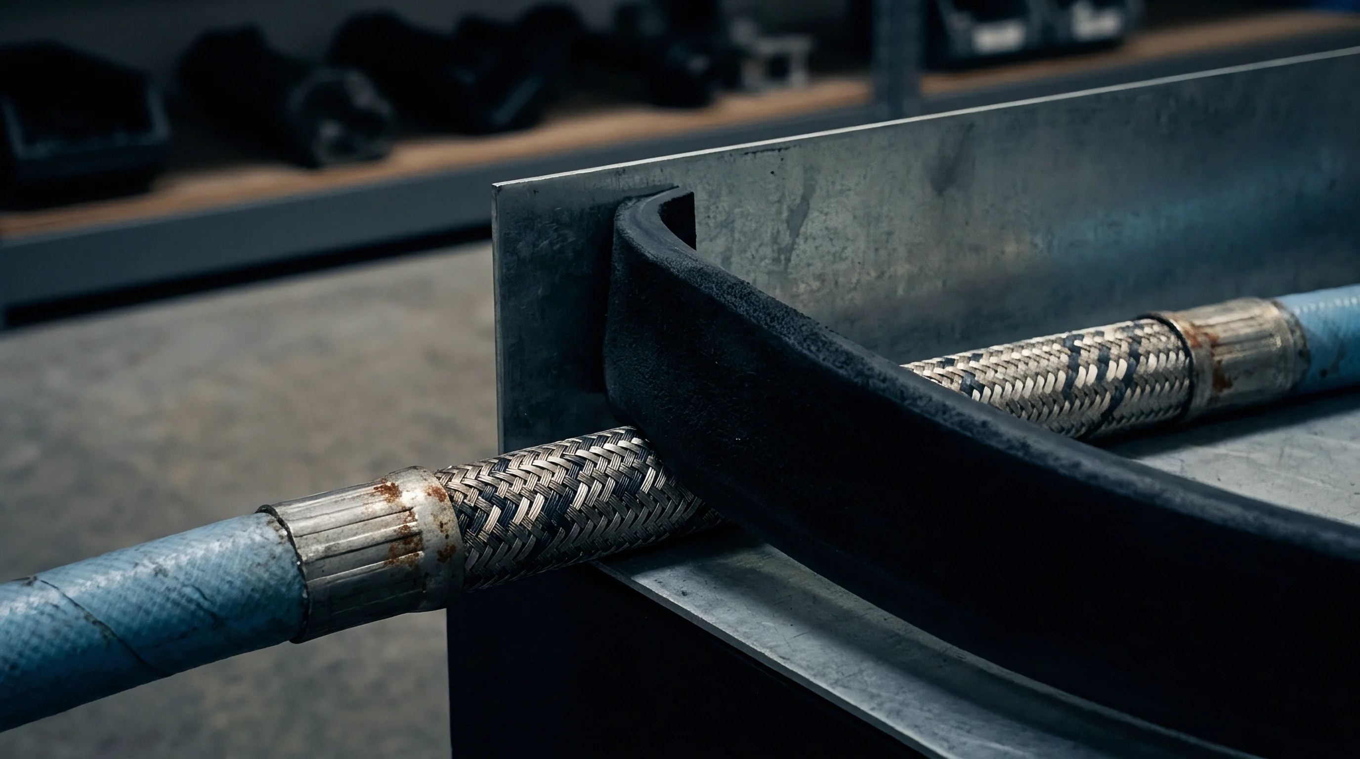
Standard tactile coordinate measuring machines operate with probe trigger forces ranging between 0.05 N and 0.15 N. When a ruby stylus contacts a thirty-durometer molded elastomer, the material compresses elastically before probe deflection triggers the internal optoelectronic switch. This local indentation records a false coordinate, reporting the surface deeper than its actual resting boundary. Dynamic scanning touch probes drag across compliant surfaces, producing stick-slip chatter that corrupts profile data sets.
Calibrating touch probe trigger force against reference spheres fails to resolve this compliance error because the calibration sphere is hardened steel or ceramic with zero surface compliance. Stylus tip diameters alter indentation depth under identical trigger loads: a small one-millimeter stylus penetrates deeper into an elastomeric skin than a five-millimeter ball tip, yielding different reported feature positions. Operators attempting to compensate through software offset routines introduce systematic errors when material hardness shifts across production batches.
Non-Contact Laser and Structured Light Performance
Laser line triangulation sensors eliminate contact force deformation entirely. Structured light fringe projection systems capture hundreds of thousands of spatial points across compliant geometries in single exposures, eliminating probe displacement risks. Optical scanning introduces alternative variables, including surface reflectivity, color variation, and ambient illumination noise.
Translucent silicones permit light penetration below the true surface boundary, scattering the laser beam and recording artificial subsurface topographies.
| Metrology Sensor Technology | Physical Deformation Risk | Acquisition Rate | Surface Optical Sensitivity | Operational Limitation |
|---|---|---|---|---|
| Tactile Trigger Probe | High (0.05 N to 0.20 N load) | 1 to 3 points per second | Zero sensitivity to color/gloss | Indentation on elastomers below 80 Shore A |
| Laser Line Triangulation | Zero contact force | 50,000 to 200,000 points/sec | High (fails on clear polymers) | Specular glare on glossy molded finishes |
| Structured Light Scanner | Zero contact force | 1,000,000+ points per frame | Moderate (requires contrast) | Subsurface scattering on translucent silicone |
| Industrial Computed Tomography | Zero contact force | Volumetric voxel array | Zero sensitivity to surface color | Scan times exceed 30 minutes per cycle |
Industrial computed tomography measures internal geometry and external surfaces without physical contact or optical reflectivity constraints. Tomography penetrates complex convoluted rubber geometries, measuring internal wall thicknesses that touch probes and optical scanners cannot reach. Scan cycles running thirty to sixty minutes limit computed tomography to first article qualification and failure forensics rather than serial lot verification.
Line throughput demands fast optical systems, forcing engineers to control surface opacity via dry aerosol coatings that risk contaminating production lots.
ISO 10579 non-rigid drawing callouts legally transfer all unconstrained gravitational deflection risks to the supplier unless the restraint parameters appear explicitly on the face of the print.
The metrology station sets the pace of lot disposition across flexible component lines. Optical systems scan profiles in seconds, yet point cloud meshing and CAD deviation alignment create computational latency at the quality workstation. Tactile probes clear programs quickly but require mechanical restraining fixtures that add loading minutes to every inspected piece.
A balancing calculation between fixturing cycle times and optical data processing determines production release velocity.
Parts that measure within tolerance on an optical bench yield out-of-spec dimensions on a touch-probe CMM.

Climate
Polymeric and elastomeric materials display thermal expansion coefficients an order of magnitude higher than structural steels. An unfilled polyamide exhibits a linear thermal expansion coefficient near 80 × 10⁻⁶ K⁻¹, whereas tool steel expands at approximately 11 × 10⁻⁶ K⁻¹. Molded parts measured in a non-climate-controlled receiving bay at 32 degrees Celsius report larger outer profiles than those inspected in a standard metrology laboratory maintained at 20 degrees Celsius.
Failing to soak parts in temperature-regulated environments generates rejection notices that reflect weather shifts rather than molding process instability.
Hygroscopic resins compound thermal variance through moisture absorption. Dry-as-molded polyamide components absorb atmospheric humidity until reaching equilibrium with ambient relative humidity levels. Moisture entry plasticizes the polymer matrix, swelling physical features and lowering durometer hardness.
A component measured two hours post-demolding carries different dimensional envelopes than the identical component inspected after seven days in transit across oceanic shipping lanes.
Viscoelastic creep alters component boundaries during storage. Components packed tightly into bulk cartons experience compressive stresses that permanently deform non-rigid seals. Inspecting parts immediately upon unpacking captures packaging set rather than free state cavity dimensions.
Setting quality criteria requires defining conditioning duration, allowing components to recover elastically on flat inspection benches before triggering coordinate sweeps.
Quality logs omitting ambient relative humidity and stabilization duration records leave inspection disputes legally unresolvable between trading counterparties.


Sampling

Sample Preparation and Stabilization Protocols
Reliable free state inspection requires consistent part conditioning sequences before measurement begins. Molded elastomeric profiles retain residual mold temperatures and internal stress distributions directly following demolding. Measuring parts before crystallization reaches thermodynamic equilibrium introduces transient dimensional drift into production records.
Production control establishes holding periods where components rest at standard room temperature conditions without stacking stress.
The sequence below defines standard pre-measurement preparation for non-rigid polymer moldings:
- Thermal equilibration isolates components in a calibration environment at 20 degrees Celsius plus or minus 2 degrees for a minimum holding period of twenty-four continuous hours.
- Packaging recovery extracts flexible parts from bulk shipping containers, laying them flat on an unconstrained surface plate to reverse shipping container compression sets.
- Surface degreasing removes residual mold release agents with an isopropyl alcohol wipe, eliminating fluid films that alter optical laser triangulation accuracy.
- Orientation alignment positions the molding against gravity datum supports without mechanical pins that could stretch or bind local elastomeric walls during resting.

Acceptance Gates and Statistical Process Readiness
Measuring flexible moldings under free state conditions inflates dimensional variance across statistical process control charts. High standard deviations suppress process capability indices (Cpk), showing apparent process instability on dimensions that assemble functionally without resistance. If a tooling engineer tightens injection parameters to correct these apparent variances, process adjustments often induce actual physical flaws like sink marks, flash, or internal voids.
Evaluating supplier capability requires separating true tooling error from measurement variation. Gauge repeatability and reproducibility (GR&R) studies on flexible moldings routinely fail classical ten-percent variance acceptance criteria when tested under free state conditions. Probe contact force, resting position variation, and operator handling contribute heavily to observed measurement error.
Establishing realistic acceptance thresholds demands qualifying the fixture and sensor combination before auditing manufacturing process performance.
Gauge repeatability studies on flexible components often register forty percent system error solely from human handling variations during unconstrained part placement.
When statistical validation demonstrates that free state measurement uncertainty exceeds thirty percent of the total tolerance band, drawing revision becomes mandatory. The design authority either widens the free state tolerance band using the ASME Y14.5 circle-F modifier or introduces explicit restrained condition callouts that eliminate gravity-induced compliance errors during inspection.
Should drawing revisions be postponed, the buyer absorbs the inspection failure costs through expanded quarantine footprints and recurring material review board overhead.

Settlement
Free state metrology disputes resolve around documented restraint conditions and defined boundary definitions. When contracts leave inspection conditions ambiguous, procurement departments pay for duplicate gauging, freight on rejected lots, and endless sorting operations. Engineering drawings must explicitly separate rigid metal expectations from flexible polymer realities through standard ISO or ASME non-rigid callouts.
Relying on implicit understanding between toolmaker and buyer guarantees commercial friction as soon as production rates scale.
The dispute mechanism rests on three distinct documentation tiers:
- Engineering drawings define explicit circle-F free state tolerances alongside restrained inspection conditions, citing specific fixture model numbers and clamping load values.
- Quality contracts state ambient temperature and humidity equilibrium boundaries, mandating twenty-four-hour environmental soaking before receiving inspection records trigger rejections.
- Fixture validation dossiers verify holding nest tolerances against component CAD data using calibrated coordinate measuring machinery prior to serial production acceptance.
Bridging the gap between raw mold capabilities and final assembly requirements prevents unneeded tooling recuts. The financial penalty for misinterpreting flexible component metrology is rarely scrap resin alone. The primary expense appears when functional tooling is altered to satisfy flawed free state inspection records, throwing assembly-level clearances out of balance.
Operations directors protect margins by standardizing metrology protocols before signing off on production expansion tooling.
The unconstrained inspection report remains an incomplete diagnostic until the resting orientation, environmental conditions, and contact forces are nailed to the floor.