Statistical Process Control Subgrouping Strategies for Multi Cavity Injection Molding
Rational subgrouping in multi-cavity molding must isolate between-cavity mold offsets from shot-to-shot press drift to prevent control chart desensitization.

Shot
A thirty-two cavity mold cycling every twelve seconds puts out ninety-six hundred parts each hour. Pulling five consecutive pieces from a collection bin beneath the drop chute looks like standard sampling, but the math that follows obscures the physics of the tool. Those five parts tumbled out of different mold positions, thermal zones, and runner branches.
Lumping them into a single Shewhart subgroup runs counter to the core premise of rational subgrouping. In Walter Shewhart’s formulation, a rational subgroup must capture only common cause variation within the group, leaving special causes to show up between groups. Multi-cavity molding inherently creates systematic geometric and thermal offsets from one cavity to the next.
Sampling across multiple cavities pools these differences into the within-subgroup range. That expands the range artificially, blowing out the control limits on an average chart and burying genuine process drifts, temperature fluctuations, and resin viscosity shifts.
Machining tolerances in the tool steel, cooling line placement, gate orifice sizes, and non-Newtonian flow behaviors guarantee that cavities will not fill identically. Even with a naturally balanced runner layout designed for symmetrical flow paths, shear heating generates thermal imbalances between inner and outer drops. Resin reaching inner cavities runs hotter and less viscous, filling faster than melt headed to the perimeter.
Piezoelectric pressure sensors behind ejector pins routinely confirm these uneven cavity pressure curves during pack and hold. Cavities under higher peak pressure produce denser, larger parts with less shrinkage, while lower-pressure cavities yield smaller parts with higher volumetric shrinkage. These cavity-to-cavity offsets remain steady cycle after cycle until physical tool wear, gate erosion, or cooling scale slowly shifts the balance.
Drawing five random pieces from a catch bin forces the subgroup standard deviation to track tool geometry rather than press repeatability. The average range balloons across subgroups. Because standard X-bar control limits are set at three sigma calculated from this inflated range, the chart loses its teeth.
Real process disturbances ~ a failing barrel heater zone, shifting regrind percentages, or check ring leakage ~ shift the average across the entire shot, yet the desensitized chart throws no out-of-control alarm.
A fifty-ton electric press holding twenty-four microns of clamp parallelism still produces seven distinct part size groupings across an eight-drop hot runner manifold.
The opposite mistake happens when technicians pull parts from just one designated cavity across consecutive cycles to monitor the whole tool. Running five consecutive shots from Cavity 4 keeps within-subgroup range very tight, because tool steel does not change shot to shot. The resulting control limits on the X-bar chart narrow drastically.
If the manifold’s thermal balance wanders, parts from Cavity 12 or Cavity 16 might drift completely out of spec while Cavity 4 sits comfortably centered. Normal cycle-to-cycle pressure flutter can also push Cavity 4 past its razor-thin limits, triggering false alarms when the mold as a whole is running well within capability.
Managing multi-cavity tools requires isolating three separate variance components: within-cavity variation across shots, between-cavity variation within the same shot, and long-term drift over hours, shifts, and resin lots. A rational subgrouping plan has to separate these sources deliberately. Picking the wrong subgroup structure ruins chart sensitivity while corrupting Cp, Cpk, Pp, and Ppk metrics.
Plant managers frequently see Cpk values over 1.67 while assembly lines reject parts that fail to fit, a mismatch that traces directly back to the sampling strategy on the floor.
High-cavitation tooling ~ like 64- or 128-cavity molds for medical disposables ~ compounds the issue. Gauging every cavity on every sampled shot creates an impossible bottleneck in the quality lab. Quality engineers must weigh inspection costs against statistical resolution.
The choice of sampling layout determines whether statistical process control functions as a working prevention system or becomes an expensive logging exercise.
Tool wear adds another layer over long production runs. Abrasive glass-filled resins wear down gate orifices under high pressure, widening the dimensional spread across cavities as the tool pushes past five hundred thousand cycles. If the subgrouping scheme does not separate cavity location from time, the engineering team cannot distinguish process instability from physical steel erosion.
Tool maintenance ends up either premature ~ wasting tool life ~ or late, after scrap rates have climbed.
The practical cost of broken sampling shows up immediately: rising scrap, heavy sorting labor, and intractable customer disputes.


Stratification
Breaking down injection molding variation into usable layers requires modeling the total observed variance mathematically. Total variance across all parts over time splits into three distinct components: within-cavity variation across consecutive press cycles, between-cavity variation within a single shot, and long-term drift across shifts and material lots. Within-cavity variance reflects machine repeatability ~ hydraulic stability, screw recovery, check ring seating, and platen parallelism.
Between-cavity variance captures mold fabrication accuracy, hot runner thermal balance, water circuit flow rates, and gate sizing. Process drift tracks changing ambient temperatures, regrind ratios, barrel heater aging, and raw resin viscosity variation.
Applying standard single-stream Shewhart equations to multi-cavity data collapses these separate layers into one unhelpful number. If a subgroup is built by pulling one part from each of k cavities in a single shot, between-cavity offsets get dumped directly into the range calculation. The sample range R ends up measuring mold imbalance rather than machine repeatability.
The upper control limit on the range chart rises, pushing the X-bar control limits outward by A2 barR. When between-cavity variation dominates, the range chart sits deceptively flat near the center line while the X-bar chart misses real process drifts that move every cavity together.
Sampling multiple consecutive parts from just one cavity creates the reverse problem. That approach isolates short-term press repeatability for that specific insert, so the within-subgroup range is small and the X-bar control limits become exceptionally tight. Any slight machine-wide adjustment sends points outside the limits, kicking off constant false alarms if the chart is treated as a proxy for the entire mold.
It captures that single block of steel while revealing nothing about the rest.

Which Subgrouping Schema Captures Within-Shot Cavity Differences?
Process engineers generally rely on three main subgrouping setups for multi-cavity tools: individual cavity charts, pooled across-cavity charts, and nested variance component models. The single-stream approach keeps dedicated X-bar and R charts for every cavity. For an eight-cavity mold, that means running eight distinct charts.
It provides clean, immediate diagnostic visibility into cavity wear or localized gate blockages without cavity offsets polluting the within-subgroup range. The drawback is the sheer data workload: a 32-cavity mold demands thirty-two separate charts, quickly burying floor personnel unless automated vision systems or coordinate measuring machines feed data directly to the software.
The pooled across-cavity approach pulls all m cavities from a single shot n. Instead of tracking conventional Shewhart averages, the analysis splits each shot into two metrics: the shot average across all cavities and the shot range across all cavities. The shot average monitors machine stability over time, while the shot range tracks mold balance.
These metrics go onto separate charts with control limits derived from differences between consecutive shots rather than within-sample ranges. Using moving ranges between consecutive shot averages isolates genuine short-term press variation while keeping mold balance on its own tracking line.
The nested variance method models part dimension Yijk as a combination of the grand mean, the fixed effect of cavity i, the random effect of shot j, and residual measurement error k. ANOVA calculations isolate the exact proportion of variance coming from tool steel offsets versus shot-to-shot machine variation. When cavity-to-cavity differences account for more than thirty percent of total variance, traditional capability metrics become statistically invalid unless computed on a per-cavity basis.
| Subgrouping Architecture | Sampling Unit | Within-Subgroup Variance Source | Between-Subgroup Variance Source | Diagnostic Sensitivity |
|---|---|---|---|---|
| Individual Cavity Charts | n parts from Cavity i across consecutive shots | Cycle-to-cycle press repeatability | Long-term press and material drift | High cavity wear detection; high clerical load |
| Shot-Average and Shot-Range | All m cavities from single shot j | Mold balance and thermal distribution | Shot-to-shot machine stability | Direct separation of press and tooling causes |
| Pooled Random Bin Sampling | n random parts from drop bin | Mixed press repeatability and mold balance | Composite system noise | Poor; desensitizes X-bar chart limits |
| Cavity-Difference Charting | Difference between Cavity i and reference Cavity 1 | Differential thermal stability | Tool wear and gate blockage | High sensitivity to balance degradation |
Molding operations frequently invest heavily in automated part-picking robots and multi-sensor metrology cells without first structuring their variance model. When these systems dump measurements into default SPC configurations, the software often pools the data into generic subgroups of five. The dashboard displays clean statistical control while assembly lines reject non-fitting parts.
Restructuring the subgroup architecture quickly exposes out-of-control conditions running quietly along specific runner branches.
Uneven cooling generates clear directional shrinkage patterns across a mold. In an eight-cavity inline tool, center cavities run hotter than outer cavities due to retained heat in the mold core unless coolant flow maintains high Reynolds numbers above four thousand. Hotter center cavities produce smaller outer diameters on molded bosses.
Lumping center and edge cavities into the same subgroup causes calculated capability to drop sharply, even when the press holds peak hydraulic pressure within two bar shot after shot.
ISO 22514-4 requires manufacturers to verify homogeneity across cavities before pooling multi-cavity data into a single capability index. If cavity distributions exhibit statistically significant mean offsets or unequal variances, the molder must either report capability per cavity or benchmark the entire mold against its weakest cavity.

Dispersion
Choosing the right control chart layout depends on cavitation, available metrology automation, and the failure modes found during mold qualification. Three charting setups dominate multi-cavity injection molding: individual X-bar and S charts per cavity, Group Control Charts, and Cavity-Difference Control Charts. Each handles dispersion differently to protect chart sensitivity.
Individual X-bar and S charts offer the cleanest diagnostic picture. On a 16-cavity tool running an optical lens, technicians might gauge critical thickness on all sixteen cavities every two hours. The software maintains sixteen separate X-bar and S charts, each calculating its center line and limits solely from that cavity’s history.
Gate wear or poor venting on Cavity 7 appears immediately as a run or out-of-control point on Chart 7, while Charts 1 through 6 and 8 through 16 stay quiet. This eliminates false alarms on healthy cavities. The limitation is inspection throughput: gauging sixteen intricate parts every two hours requires dedicated optical equipment.
Group Control Charts offer a practical alternative for shops relying on manual gauging. Developed by British statisticians in the 1940s and adapted for plastics processing, the Group Control Chart tracks only the maximum and minimum cavity measurements from each sampled shot. Technicians measure every cavity in a shot, find the highest value (Xmax) and lowest value (Xmin), and plot those two points on a single chart, tagging each with its cavity number.
The chart uses standard limits based on the average within-cavity moving range.
A machine-wide shift moves both Xmax and Xmin in tandem. A local tooling problem ~ like a partially blocked gate or localized wear ~ causes the same cavity number to show up repeatedly as the plotted extreme. If Cavity 12 appears as the maximum value across seven consecutive subgroups, that run flags a cavity-specific special cause.
Group Control Charts compress dozens of measurement streams into a manageable view without losing sensitivity to machine drift or cavity-level defects.
Group control charts compress thirty-two cavity measurement streams into two plotted boundary points without sacrificing statistical sensitivity to individual cavity degradation.
Cavity-Difference Control Charts track the offset between each individual cavity and either a master cavity or the shot average. For shot j, the metric for cavity i is Dij = Xij – barXj, where barXj represents the shot mean. Plotting Dij filters out cycle-to-cycle press fluctuations entirely, leaving only mold balance, gate balance, and localized cooling behavior on the chart.
Because these difference charts carry very tight limits, any excursion points straight to tooling issues like blocked cooling channels, gate debris, or core deflection under clamp load.
| Chart Method | Plotted Statistic | Center Line Formula | Upper Control Limit Formula | Primary Failure Mode Detected |
|---|---|---|---|---|
| Individual Cavity X-bar | barXi = frac1nsum Xik | barbarXi | barbarXi + A2 barRi | Cavity-specific steel wear, gate erosion |
| Individual Cavity S | Si = sqrtfracsum (Xik – barXi)2n-1 | barSi | B4 barSi | Localized venting degradation, flash formation |
| Group Control Chart (GCC) | Xmax and Xmin per shot | barbarX | barbarX + 3 fracbarSwithinc4 | Systemic press drift and extreme cavity offsets |
| Shot Range Chart (Rshot) | Rshot = Xmax – Xmin | barRshot | D4 barRshot | Hot runner manifold thermal imbalance |
| Cavity-Difference (Dij) | Dij = Xij – barXj | barDi | barDi + 3 hatσdiff | Differential core deflection, cooling line blockage |
Measurement system error interacts directly with subgroup dispersion. In multi-cavity SPC, Gage R&R needs to be judged against the within-cavity process variation, not total part tolerance. If an optical gaging system carries a repeatability standard deviation of two microns against a within-cavity process standard deviation of four microns, measurement error eats up fifty percent of the within-subgroup spread.
That widens the control limits on individual cavity charts, hiding subtle process shifts. Metrology qualification must confirm that measurement variance stays below ten percent of the within-cavity variance component.
High-cavitation tooling is also vulnerable to thermal disruption during mold stops. When a press sits idle for two minutes to clear a stuck part, resin cooks in the hot runner tips. The first five shots after startup show significant dimensional scatter.
If operators pull parts during this recovery window and log them into standard SPC subgroups, the dispersion data gets badly skewed. Sampling procedures have to enforce steady-state rules, redirecting warm-up parts to containment bins.
In high-volume cells, technicians sometimes try to lighten the inspection load by rotating through cavities ~ checking Cavity 1 on Monday, Cavity 2 on Tuesday, and so on. This rotating method creates an illusion of control while turning constant tool offsets into artificial time-based trends. The resulting trend lines show sharp steps at shift changes, prompting technicians to tweak barrel heats to fix what is actually just cavity-to-cavity variation.
Dimensional steps between cavities are sometimes written off as normal shrinkage variations inherent to semi-crystalline resins.


Matrix
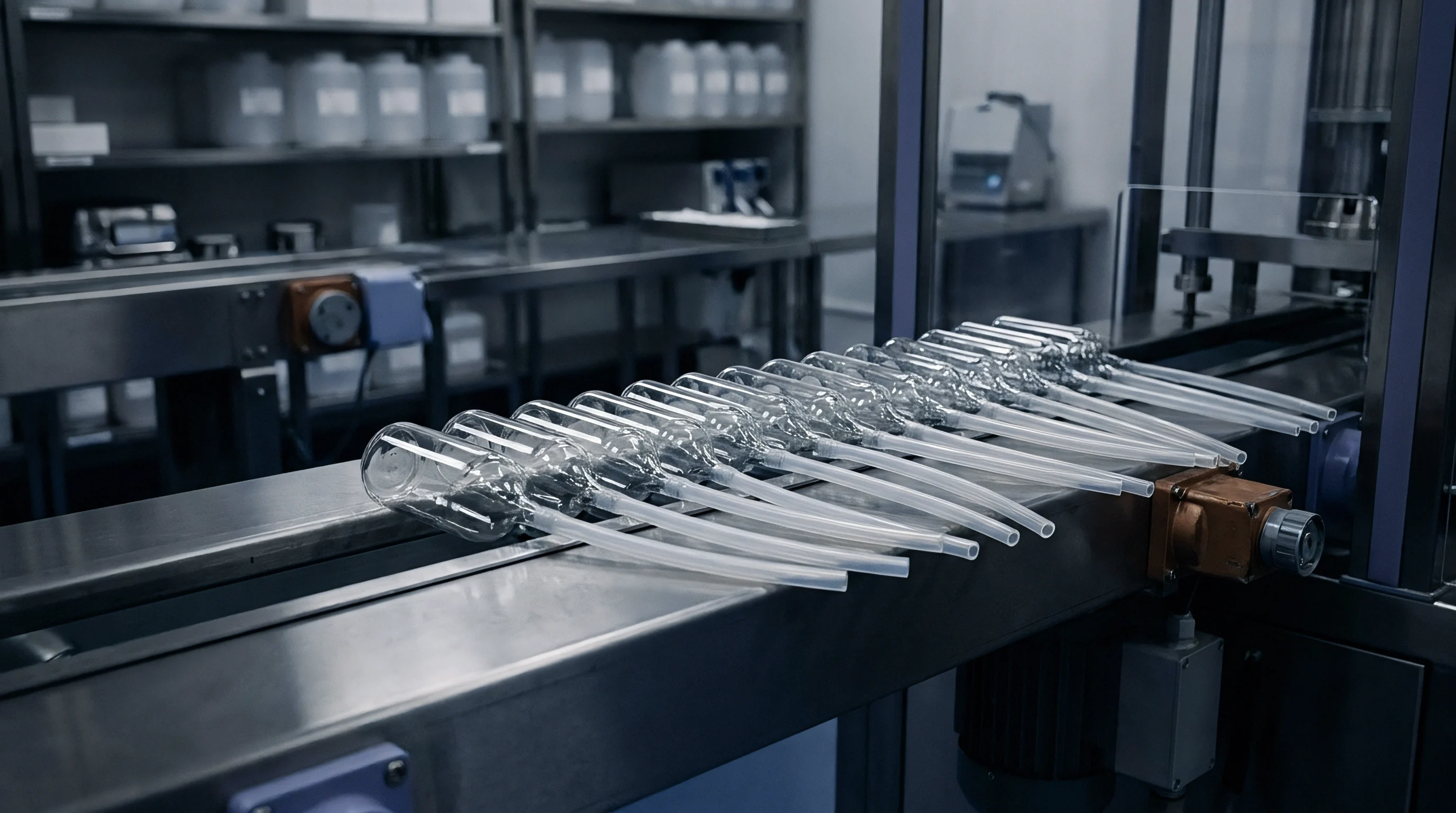
Building an effective subgrouping matrix means matching the tool’s architecture, part tolerances, and cycle times to an appropriate statistical layout. A 4-cavity bracket mold demands a very different sampling plan than a 96-cavity pipette mold. Cavitation sets the practical inspection limit and defines where undetected defects are most likely to hide.
For low-cavitation molds with two to eight cavities, measuring complete shots is straightforward. Every cavity from the sampled shot is measured on critical dimensions, giving full visibility into tool balance and machine stability without overloading the quality lab. Medium-cavitation tools with sixteen to thirty-two cavities often strain manual metrology.
These cells benefit from rotating block sampling or automated optical gauging. In rotating block schemes, a complete shot is pulled, but technicians measure only a designated quadrant or block each cycle ~ cycling through all cavities over four intervals while running a full shot balance check once per shift.
Should Rational Subgrouping Separate Mold Balance Effects?
Separating mold balance from press repeatability is essential in precision molding. Blending them into a single subgroup distorts capability indices and makes automated root-cause detection impossible. When an alarm fires in a decoupled monitoring system, maintenance immediately knows whether to send a mold technician to check heater bands or a process technician to inspect the check ring.
High-cavitation molds running 64 to 128 cavities require a tiered sampling matrix. Gauging 128 parts every interval is impractical without inline 3D optical scanning. A tiered structure balances high-frequency monitoring on sentinel cavities with lower-frequency full-shot balance checks:
- High Frequency Critical Cavity Subgrouping monitors four sentinel cavities every hour, selecting the two historically largest and two historically smallest cavities identified during initial mold qualification.
- Full Shot Mold Balance Subgrouping measures all cavities across a single complete shot once every twenty-four hours to verify that the spatial balance profile remains stable.
- Machine Process Parameter Subgrouping captures digital transducer data, including cavity pressure integral, peak hold pressure, and cushion position, across every shot from the machine controller.
- Automated Gate Freeze Verification monitors part weights from individual cavities across three consecutive shots whenever resin lot numbers change.
| Cavitation Tier | Recommended Subgroup Structure | Sampling Frequency | Metrology Method | Primary Statistical Risk |
|---|---|---|---|---|
| Low (2 to 8 cavities) | Complete shot, all cavities individual charts | Every 2 hours or 500 cycles | Manual digital calipers or optical comparator | Operator data entry lag |
| Medium (16 to 32 cavities) | Group Control Chart (Xmax and Xmin) | Every 4 hours or 1,000 cycles | Multi-sensor CMM or vision fixture | Masking intermediate cavity drift |
| High (64 to 128 cavities) | Tiered: 4 sentinel cavities plus daily full shot | Sentinel hourly; full shot daily | Automated structured-light 3D scanning | Undetected wear on unmonitored cavities |
| Family Molds (Dissimilar parts) | Individual charts per cavity geometry | Every shot sequence sample | Dedicated custom drop gages or vision | Applying uniform limits to dissimilar flow paths |
Family molds, which produce different components in the same tool frame, rule out pooled subgrouping entirely. When a family mold makes an upper housing, lower housing, and battery cover in one shot, each cavity sees distinct flow rates, cooling rates, and shrinkage dynamics. Pooling them generates meaningless statistical noise.
Each cavity has to be managed as an independent production line with its own subgroup plan, control limits, and capability tracking.
Sample sizes for single-cavity tracking come down to statistical power. A subgroup of n=5 consecutive shots from a single cavity offers eighty percent power to catch a 1.5 sigma mean shift within two sampling cycles. Bumping the sample to n=10 doubles the gauging workload for very little diagnostic gain.
For automated inline systems checking every single part, moving average or EWMA charts with n=1 work better than standard X-bar charts, using smoothing parameters (λ = 0.1 to 0.2) to pick up gradual thermal drift.
Manifold zoning also dictates subgroup design. In an eight-drop hot runner where each drop feeds four sub-cavities through cold runners, temperature is controlled per drop. A heater band failure on Zone 3 hits all four sub-cavities on that drop at once.
A subgroup layout that averages parts across different manifold zones will hide that drop-level drop in temperature. Structuring the matrix around hot runner zones makes thermocouple and heater failures immediately obvious.
What remains unresolved is how best to automate real-time boundary limit adjustments when regrind blends introduce continuous, unpredictable viscosity shifts across long production runs.

Execution
Putting a subgrouping plan into practice requires clear operating procedures, permanent cavity identification, and firm containment protocols. Floor operators work under constant cycle targets; if an SPC procedure involves complicated math or convoluted sorting, execution slips and the data quickly becomes unreliable.
Physical cavity identification is fundamental. Every cavity insert needs a legible cavity ID cut directly into the tool steel in an unobtrusive area of the part. If maintenance polishes an insert or swaps a component, that marking must remain clear.
When parts drop onto a belt or into a bin, legible cavity numbers allow sorting personnel to isolate suspect cavities during an out-of-control condition without placing the whole lot on hold.
Automated collection cuts out transcription errors and speeds up feedback. Modern molding cells use handling robots to strip parts off ejector pins while preserving cavity orientation, placing parts into designated lanes on an inspection belt or straight into a multi-nest vision fixture. The fixture measures critical dimensions, links each dimension to its cavity ID, and pushes the data stream directly to the plant’s SPC system.
When the software flags an out-of-control event ~ whether a single point outside the three-sigma limit or nine consecutive points on one side of the mean ~ the floor response must follow a defined sequence:
- Containment of Affected Cavity Inventory isolates all production from the specific out-of-control cavity generated since the last successful in-control subgroup sample.
- Verification of Machine Cushion and Press Parameters confirms whether the injection unit maintained stable hydraulic peak pressure, plasticizing time, and screw cushion position during the suspect cycles.
- Inspection of Mold Parting Line and Vents checks the physical mold face for plastic flash, oil contamination, or crushed vents on the flagged cavity position.
- Dynamic Tool Cavity Deactivation Protocol executes a controlled shut-off of the individual hot runner nozzle or mechanical plug of the cold runner gate if an isolated cavity suffers physical damage.
Shutting off a damaged cavity changes the mold’s hydraulic and thermal balance. If a technician plugs the gate on Cavity 4 in a 16-cavity tool, the melt meant for that cavity shifts to the remaining fifteen. Injection speeds jump slightly, peak cavity pressures rise, and parts from active cavities grow in both weight and size.
Whenever a cavity is dropped, quality engineers have to recalculate the control limits for the active cavities to establish a valid baseline for the altered tool.
A plugged gate on a thirty-two cavity tool increases pack pressure in adjacent cavities by up to nine percent within three cycles.
Operations teams occasionally claim full statistical control while running tools with several deactivated cavities under original baseline limits. This practice masks the dimensional growth in the remaining cavities, passing oversized parts to downstream assembly. Quality protocols must link mold configuration changes directly to SPC control limit revisions in the plant database.
Floor audits should regularly verify that sample timing matches the planned matrix. Grabbing subgroups right after switching a drying hopper or running a barrel purge introduces unrepresentative noise into the data. Parts must be collected only while the press is running in steady-state automatic mode.
If an alarm sounds, technicians need to follow the diagnostic flowchart rather than just clearing the fault on the press screen.
Stable cavity balances across the mold face confirm healthy tooling steel before volume production begins.