Dynamic Warpage Mitigation Strategies in High Density Laminate Package Assemblies
Balancing copper density, selecting ultra-low expansion glass cores, and profiling post-mold curing prevents dynamic warpage in high density laminate assemblies.

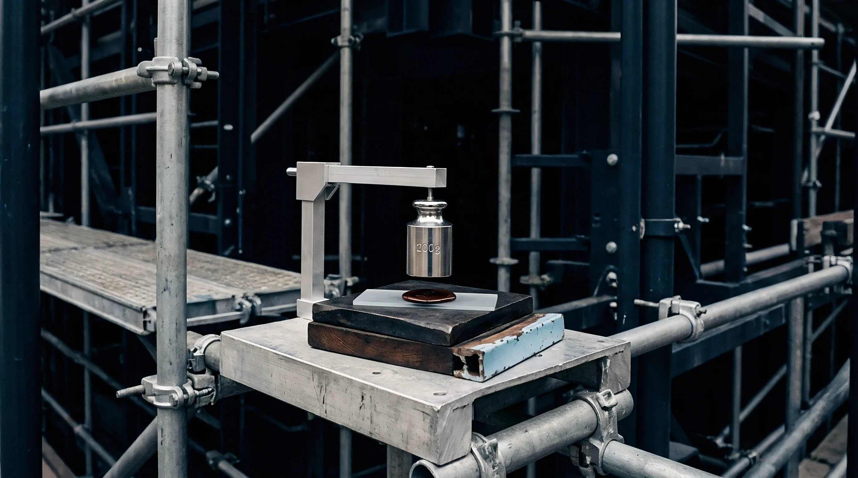
Mechanics
High density laminate package assemblies undergo structural distortion during thermal reflow processes due to material thermal expansion mismatches. Silicon integrated circuits possess a low coefficient of thermal expansion ranging between 2.6 and 3.2 ppm/°C. Organic laminate substrates exhibit significantly higher coefficient of thermal expansion values, typically between 10 and 17 ppm/°C. During the reflow cycle, temperatures ascend from ambient 25°C room conditions to peak soldering thresholds reaching 260°C. Solder interconnects solidify around 183°C for eutectic leaded formulations or 217°C for lead-free tin-silver-copper alloys. Non-linear deformation occurs as constituent polymers pass through their glass transition temperatures, changing the structural behavior of the package assembly.
Deformation characteristics vary dynamically as temperature shifts. Ambient conditions often yield a convex shape, colloquially referenced as a smiling bowl profile, where substrate corners curl downward relative to the center. Elevated temperatures above 200°C invert this strain distribution into a concave shape, known as a crying bowl profile, pushing substrate corners upward.
Silicon CTE remains virtually constant. Copper trace expansion dominates room temperature behavior. Polymer resin matrix expansion governs elevated temperature distortion.
Shadow Moiré optical interferometry tracks these topographic inversions across the full thermal profile specified in JESD22-B112A.
Package non-coplanarity exceeding 175 micrometers across a 55 by 55 millimeter substrate during peak reflow induces non-wet solder open defects in over four percent of peripheral interconnects.
Coplanarity thresholds set by surface mount technology processing lines restrict allowable out-of-plane displacement. Differential expansion induces shear stresses at the interface between flip-chip solder bumps and substrate bond pads. Extreme curvature causes solder bridging between adjacent bumps at the package perimeter, generating electrical short circuits.
Uncorrected concave flexing pulls corner bumps completely apart before solder solidification occurs. Non-wet open failures result directly from this spatial separation during cooling.
| Material Component | CTE Below Tg (ppm/°C) | CTE Above Tg (ppm/°C) | Elastic Modulus at 25°C (GPa) | Elastic Modulus at 250°C (GPa) |
|---|---|---|---|---|
| Silicon Die | 2.8 | 2.8 | 130 | 130 |
| Standard BT Resin Substrate | 15.0 | 45.0 | 22 | 11 |
| Low-CTE ABF Build-Up Film | 12.0 | 28.0 | 8 | 2 |
| E-Glass Fabric Core | 6.0 | 6.0 | 72 | 72 |
| NE-Glass Fabric Core | 3.3 | 3.3 | 85 | 85 |
| Copper Trace / Plane | 16.7 | 16.7 | 120 | 105 |
Interconnect failure rates scale with die dimensions and substrate surface area. Large single-die or multi-chip modules spanning dimensions greater than 45 millimeters on a side concentrate severe strain at die corners. Micro-cracking within ultra-low dielectric constant layers under the copper pillar bumps presents an immediate reliability risk.
Differential thermal contraction during the cooling ramp phase imposes localized tensile forces that fracture fragile organosilicate glass dielectrics. The physical mechanics demand active strain counter-measures prior to committing packages to volume reflow runs.
Proceeding with uncorrected thermal deformation causes yield fallout at surface-mount assembly lines, leading to scrapped high-density boards and unrecoverable module field failures.

Core
Advanced dielectric materials and woven reinforcement glass fabrics define the structural stiffness of organic package substrates. Reinforcement choice dictates overall substrate thermomechanical performance. Traditional E-glass fabric displays an isotropic coefficient of thermal expansion near 6.0 ppm/°C. Specialized NE-glass fabric drops this value to 3.3 ppm/°C, matching silicon thermal behavior more closely.
Glass fabric weave density alters planar rigidity. Plain weave patterns provide balanced axial support, whereas asymmetric twill or satin weaves introduce localized stiffness variations across x and y axes.
Resin formulations filled with micro-silica particles alter composite matrix properties. Unfilled epoxy or bismaleimide-triazine resins present high expansion rates combined with dramatic modulus drop-offs above glass transition temperatures. Loading resins with 70 to 85 weight percent spherical silica particles suppresses thermal expansion.
Higher filler loading increases room-temperature elastic modulus beyond 20 GPa. Excessive filler loading increases resin viscosity during lamination, risking void formation around fine-pitch copper traces. Dielectrics contract upon cooling.
Compliance with IPC-TM-650 Method 2.4.22 dictates glass transition temperature verification via thermal mechanical analysis to prevent unexpected modulus drops during reflow.
Substrate thickness scaling introduces profound mechanical trade-offs. Legacy substrate designs utilized rigid central cores measuring between 0.8 and 1.2 millimeters in thickness to suppress warpage. High-density interconnect architectures favor thin cores measuring 0.1 to 0.4 millimeters or eliminate the central core entirely.
Coreless substrate structures yield minimal package height and superior thermal dissipation profiles. Coreless architectures suffer from extremely low flexural rigidity. Thermal stress relief in coreless layers depends entirely upon balanced dielectric buildup chemistries.
- Glass cloth thermal matching specifies NE-glass fabric over standard E-glass to reduce in-plane coefficient of thermal expansion divergence between silicon dies and organic cores.
- Silica filler concentration targets an optimal 78 weight percent threshold to maximize flexural modulus without impeding build-up layer resin flow around micro-vias.
- Dielectric glass transition height requires resins exhibiting glass transition values exceeding 180°C to maintain structural modulus during lead-free soldering profiles.
- Thickness ratio symmetry balances core thickness against upper and lower dielectric layer build-ups to prevent neutral plane shifting during thermal cycling.
A specific material figure in current packaging data sheets lists an in-plane CTE of 10 ppm/°C for advanced build-up films. This value rests on empirical thermomechanical analysis tests conducted at a 5°C per minute heating rate on unpatterned dielectric sheets across a 25°C to 150°C thermal window. In actual multi-layer patterned substrates, localized copper density variations push effective regional CTE to 13.5 ppm/°C. Standard laboratory tests on homogenous dielectric samples fail to predict localized strain gradients created by real circuit routing layouts.
Selecting substrate dielectrics with glass transition temperatures far above peak soldering thresholds prevents non-linear thermal expansion surges during assembly.

Cure
Thermal ramp rates and isothermal hold steps during polymer processing govern residual stress accumulation within multi-layer laminate packages. Dielectric resins and underfill encapsulation materials shrink during chemical polymerization. Gelation points mark the phase transition where cross-linking polymer chains form rigid network structures.
Shrinkage occurring prior to gelation generates minimal mechanical stress because fluid resin flows to relieve strain. Polymerization shrinkage occurring after gelation locks locked-in tensile stresses directly into the assembly matrix.
Fast single-stage curing cycles produce severe internal residual stress profiles. Rapid heating forces resin cross-linking to occur under steep thermal gradients. Non-uniform reaction kinetics across package cross-sections trap unbalanced viscoelastic strain within inner layers.
Multi-stage stepped curing profiles mitigate this build-up. An initial low-temperature hold step below the gel point allows uniform chain propagation throughout the material volume. Subsequent temperature steps advance full molecular cross-linking while permitting viscoelastic stress relaxation to dissipate locked-in strain before final cool-down.
Can Thermal Ramp Modification Prevent Inversion Point Failure?
Adjusting post-mold cure thermal cycles alters the mechanical baseline of molded interconnect packages. Epoxy molding compounds exhibit viscoelastic stress relaxation during extended elevated temperature exposure. Holding assemblies at 175°C for four to six hours allows locked-in polymer chain stress to relax mechanically.
Slow furnace cooling at rates under 1.5°C per minute prevents thermal shock and minimizes planar strain differences between upper mold caps and lower organic laminates. Post-mold curing settles residual polymerization stresses.
Lowering post-mold baking temperatures while extending hold times reduces frozen-in polymer stress without compromising chemical cross-linking density.
- Position assembled substrates into a programmable nitrogen-purged convection oven equipped with multi-zone heating controls.
- Ramp oven temperature from ambient 25°C to 100°C at a strictly controlled rate not exceeding 2.0°C per minute.
- Maintain isothermal soak at 100°C for 30 minutes to homogenize thermal distribution across high-density copper plane areas.
- Ramp temperature at 1.0°C per minute to the primary polymer gelation threshold of 150°C.
- Hold at 150°C for 60 minutes, allowing controlled cross-linking while minimizing gel-point mechanical stress generation.
- Increase temperature to the final cure setpoint of 175°C at 1.5°C per minute.
- Execute final isothermal post-mold cure bake at 175°C for 240 minutes to establish maximum cross-linking density.
- Cool assemblies down to 35°C at a gradual ramp rate below 1.0°C per minute to prevent thermal gradient shock.
Viscoelastic relaxation behavior shifts significantly between manufacturing sites due to ambient relative humidity absorption prior to baking. Absorbed moisture lowers effective resin glass transition temperatures, changing viscoelastic response rates during initial heating ramps. Outgassing moisture creates internal steam pressure inside micro-voids, increasing delamination risks.
De-binding pre-bakes at 125°C for two hours prior to primary cure profiles drive out ambient moisture content, stabilizing chemical reaction baselines.
Substrate suppliers frequently attribute localized warpage variations to uncontrollable batch-to-batch polymer raw material resin fluidity tolerances rather than defective press thermal uniformity.
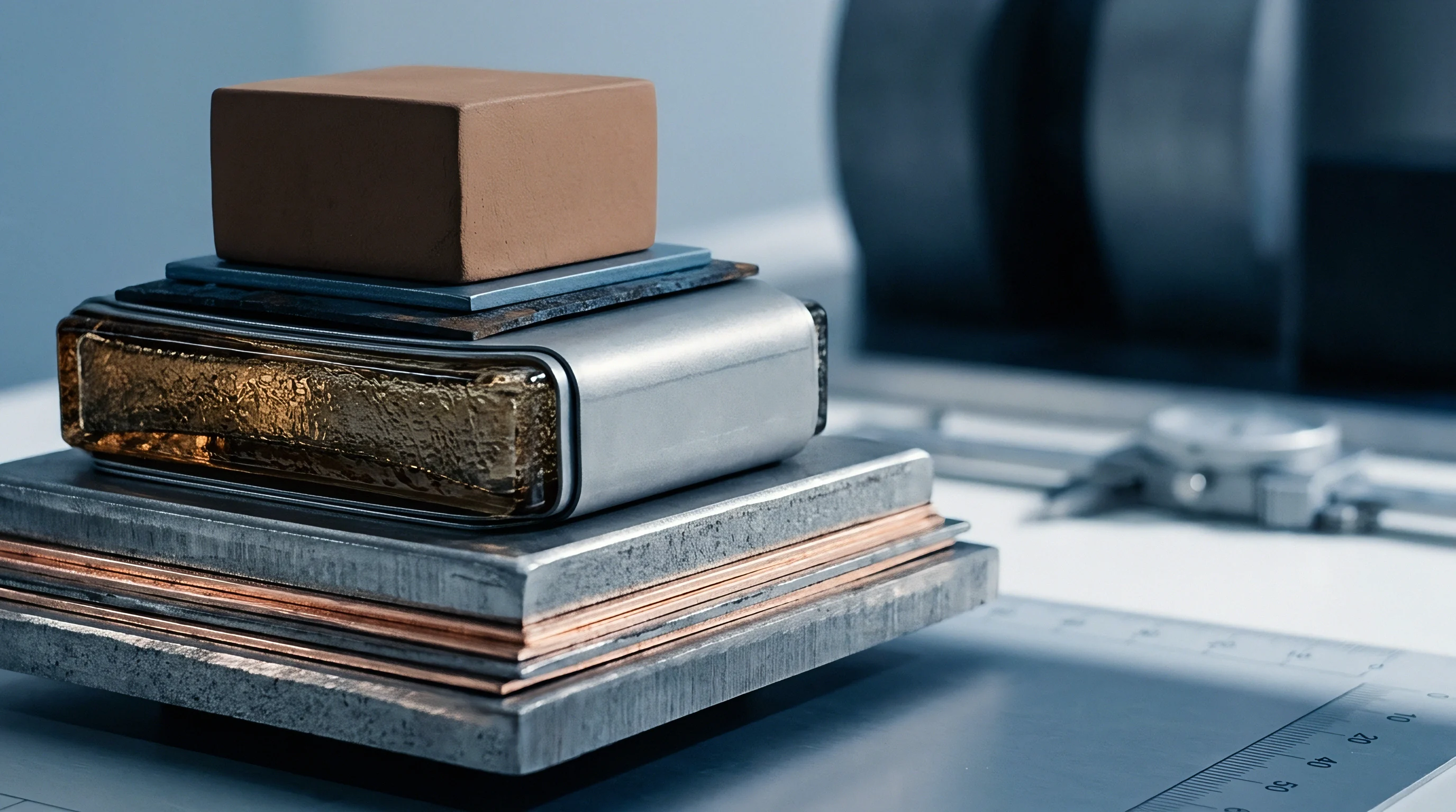
Balance
Symmetric copper density layout across dielectric layers prevents asymmetrical bending moments during thermal excursions. Printed circuit board and package substrate designs contain functional signal layers, ground planes, and power delivery planes. Signal layers possess sparse copper coverage, often between 20 and 35 percent surface area utilization.
Power and ground planes feature continuous copper fills approaching 85 to 95 percent coverage. Placing high-density copper planes exclusively on lower layers creates an immediate structural imbalance relative to sparse upper signal layers.
Thermal profiles alter polymer cross-linking states. Asymmetrical copper distributions shift the physical location of the substrate composite neutral axis. When heating occurs, layers with higher copper volume fractions resist expansion due to copper’s lower CTE relative to unreinforced resin.
Layers with lower copper density expand freely at rates dictated by resin properties. Asymmetrical copper structures induce bending moments. The bending moment acts continuously across thermal profiles, converting uniform volumetric expansion into dramatic planar bending deformation.
| Layer Construction (Top / Bottom Ratio) | Equivalent Top Layer Copper % | Equivalent Bottom Layer Copper % | Neutral Axis Displacement (µm) | Peak Reflow Warpage (µm) |
|---|---|---|---|---|
| Balanced Standard (1.00) | 65 | 65 | 0.0 | 42 |
| Moderate Imbalance (1.33) | 60 | 45 | +12.4 | 118 |
| Severe Imbalance (2.00) | 70 | 35 | +28.9 | 215 |
| Extreme Imbalance (3.00) | 75 | 25 | +46.2 | 310 |
Dummy copper tiling balances layout density across sparse routing layers. Automated electronic design tools inject un-routed copper meshes or solid copper dot arrays into open dielectric regions. Cross-hatched copper thieving patterns match the effective copper area fraction of adjacent solid power planes without generating large eddy current loops.
Tiling copper uniformly across all signal layers anchors spatial thermal expansion coefficients across x and y planes equally.
Copper percentage discrepancies between top and bottom build-up layers directly shift the neutral axis during thermal reflow cycles.
Substrate coreless stackups demand absolute cross-sectional mirror symmetry around the center plane. An eight-layer coreless design requires dielectric thickness, copper thickness, and trace density on Layer 1 to equal Layer 8 precisely. Layer 2 must mirror Layer 7, Layer 3 must mirror Layer 6, and Layer 4 must mirror Layer 5.
Deviating from strict cross-sectional structural symmetry by omitting copper planes on inner layers guarantees package twisting during cooling phases.
Commercial packaging data contains a warpage tolerance window that this desk cannot fully defend: a maximum 100-micrometer coplanarity limit across 60 by 60 millimeter panel substrates. This published limit omits spatial mapping conditions, measurement point density, and exact support pin locations used during optical profiling. Under this technical uncertainty, careful package buyers specify custom Shadow Moiré fixtures with standardized edge-support conditions directly inside purchase orders to prevent false acceptance readings.
Incorporating JESD22-B112A coplanarity acceptance limits directly into substrate supply agreements obligates fabricators to verify copper density parity on every production batch before release.
Stiffener
External structural rings and metallic caps attached to organic substrates counteract intrinsic dynamic warpage forces. Metal stiffener rings, machined from high-modulus materials, provide peripheral flexural rigidity. Standard stiffener materials include nickel-plated copper (C1100), stainless steel (SUS430), and copper-invar-copper (CIC) composite alloys.
Copper features high thermal conductivity but a high CTE of 16.7 ppm/°C. Stainless steel provides a lower CTE near 10.4 ppm/°C with high mechanical yield strength. Copper-invar-copper cladding achieves engineered CTE matching down to 4.5 ppm/°C while maintaining structural stiffness.
Corner relief notches reduce localized stress concentration. Solid rectangular picture-frame stiffeners concentrate intense shear forces at inner ring corners during thermal cycling. These localized stress concentrations cause adhesive delamination between the metal frame and the laminate substrate surface.
Machining radius cutouts or corner slots into the stiffener geometry redistributes thermal strain evenly along the perimeter edge. Stiffener thickness ratios typically range between 0.8 and 1.5 times the total substrate thickness to optimize mechanical restraint against added package weight.
Adhesive curing shrinkage adds compressive strain. The polymer adhesive layer securing the metal frame to the organic laminate determines load transfer efficiency. High-modulus epoxy film adhesives transmit mechanical restraining forces effectively but require elevated cure temperatures.
Dispensed liquid epoxies cure at lower temperatures but display higher thermal expansion rates. Adhesive thickness must be controlled precisely between 30 and 50 micrometers. Excessively thin adhesive lines result in voids, whereas thick adhesive lines allow mechanical creep, diminishing the restraining action of the stiffener frame.
- Interfacial adhesive delamination occurs when shear stresses exceed the bond strength between the metallic stiffener ring and the organic substrate solder mask interface.
- Silicon die cracking arises when an excessively rigid, low-CTE stiffener ring transfers bending strain into the central die region during cooling ramps.
- Substrate warpage inversion develops if the stiffener adhesive glass transition temperature falls directly inside the operational reflow window, causing structural support loss.
- Corner solder joint fracture results from differential expansion between the outer stiffener ring edge and underlying printed circuit board interconnects.
Thermal management considerations in silicon wafer processing centers dictate specific temperature budgets during front-end fab operations to avoid wafer bowing. Similarly, back-end packaging processes rely on mechanical constraints to stabilize organic substrates through subsequent assembly steps. Stiffener attachment sequencing alters the final residual strain state.
Attaching stiffeners at the substrate panel level before die mounting provides a flat baseline for flip-chip placement. Attaching stiffeners after chip attachment and underfill dispensing allows the frame to restrain combined die and substrate thermal distortion simultaneously.
Whether future ultra-large multi-die organic package architectures can maintain structural integrity without transitioning to silicon or glass core substrates remains an open question across the advanced packaging sector.