Thermal Boundary Layer Instabilities and Viscoelastic Melt Degradation during High Throughput Molding
High throughput molding requires balancing injection velocity against viscous dissipation to prevent polymer chain scission and wall slip defects.


Layer
High-speed injection creates sharp temperature gradients inside thin-wall mold channels. When polymer melt fills a cavity at linear speeds between three hundred and eight hundred millimeters per second, contact with cold steel forms an instant solid skin. This frozen layer narrows the available flow path, forcing the core melt through a tighter channel.
Within the microscopic boundary adjacent to the skin, steep velocity gradients generate heavy localized friction.
Viscous heating inside this boundary film scales with dynamic viscosity and the square of shear rate. At high injection speeds, local shear rates along the boundary often exceed one hundred thousand reciprocal seconds. Shear heat accumulates faster than the cold mold wall dissipates it, turning the thin film into an active heat source.
Boundary layer temperatures can spike thirty to sixty degrees Celsius above the barrel setpoint, driving rapid drops in local melt viscosity.
Boundary layer instabilities develop when this temperature spike breaks the uniformity of the flow front. Core melt near the channel center remains close to setpoint temperatures with higher viscosity, whereas material along the boundary thins drastically under the heat. A viscosity drop that steep across less than two hundred micrometers destabilizes flow, causing localized jetting, shear banding, and flow front hesitation.
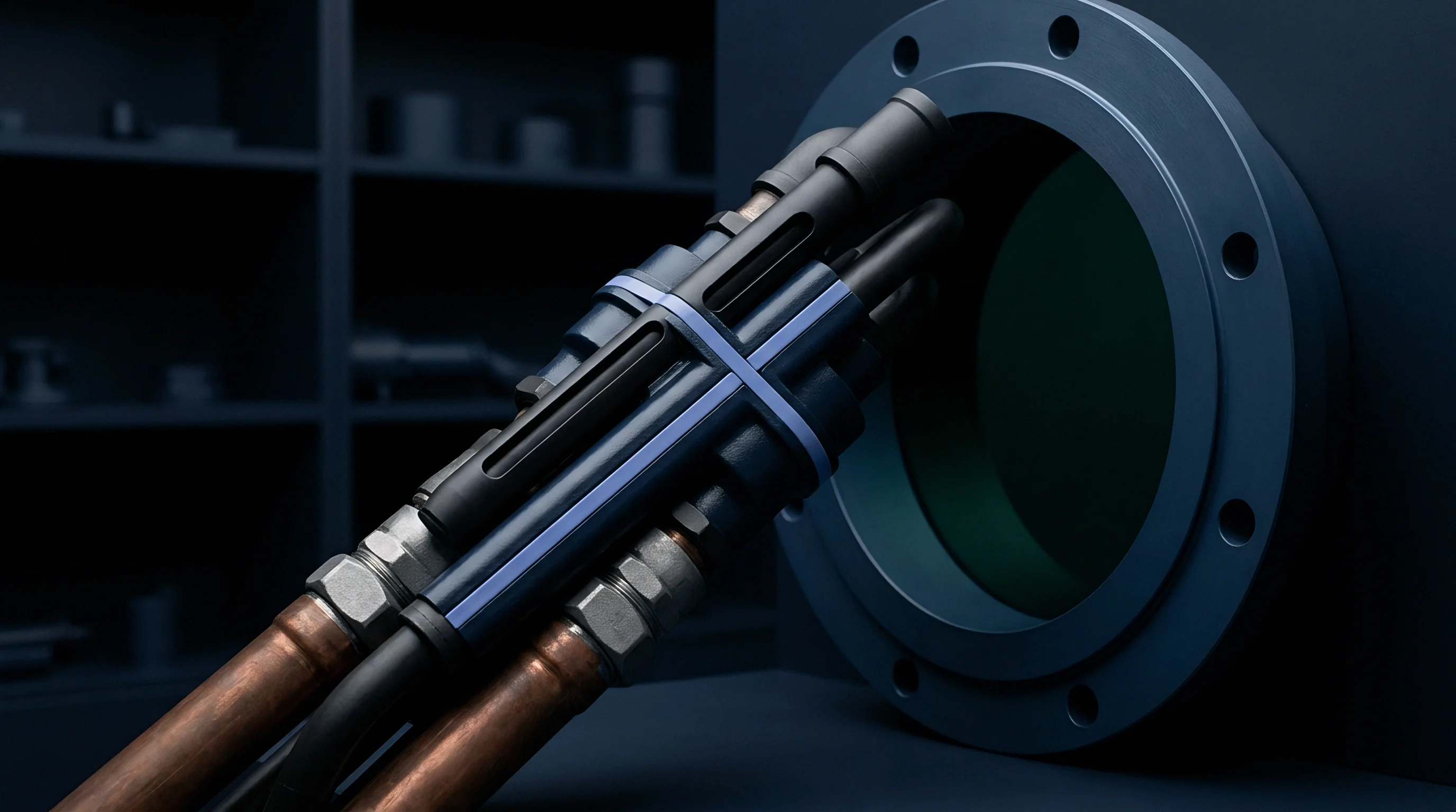
Boundary Film Physics under High Velocity Inflow
Short fill times push molten polymer past cold tool steel at speeds exceeding five hundred millimeters per second, driving the Graetz number ~ the ratio of thermal convection to conduction ~ up by orders of magnitude. A high Graetz number indicates that advective heat in the stream far outweighs conductive losses to the mold wall during fill. Consequently, the thermal boundary layer stays thin yet concentrates substantial heat.
Energy balance within the moving layer relies on the Brinkman number, which balances viscous dissipation against conductive heat transfer across the cooling interface:
Br = (η v²) / (k (Tm – Tw))
Where η represents dynamic melt viscosity, v represents average flow velocity, k represents polymer thermal conductivity, Tm represents nominal melt temperature, and Tw represents cavity wall temperature. Once the Brinkman number exceeds two, viscous dissipation outpaces conductive cooling, pushing local melt temperatures beyond safe material limits.
| Resin Type | Nominal Melt Temp (°C) | Tool Wall Temp (°C) | Calculated Brinkman No. | Boundary Temp Spike (°C) | Frozen Layer Thickness (μm) |
|---|---|---|---|---|---|
| Polyetheretherketone (PEEK) | 385 | 180 | 2.84 | +52 | 45 |
| Polycarbonate (PC) | 300 | 90 | 2.41 | +41 | 62 |
| Thin-Wall Polypropylene (PP) | 230 | 40 | 1.95 | +33 | 88 |
| Liquid Crystal Polymer (LCP) | 335 | 110 | 3.12 | +64 | 28 |
| Data recorded using in-situ fast-response coaxial thermocouples at gate land region under steady-state injection conditions. | |||||
Thin-wall tooling magnifies these effects by forcing high volumetric flow rates through gaps under one millimeter. Core velocities stay high while the outer layer undergoes severe shear. Skin growth is seldom uniform along the runner; local thermal spikes re-melt portions of the initial frozen shell, creating periodic thickness variations that distort cavity filling.

Thermal Instability Dynamics along Channel Walls
At high injection rates, boundary layer formation occurs under dynamic non-isothermal conditions. Rapid wall cooling continually tries to freeze the outer skin, while shear dissipation generates heat that opposes cooling. This competition produces an unstable thermal equilibrium at the melt-steel interface.
Minor variations in runner balance, cooling flow, or hydraulic pressure easily disrupt this equilibrium. If shear heating temporarily exceeds heat extraction, the frozen skin thins, lowering local flow resistance and pulling additional melt along that path. This drives filling imbalances across multi-cavity tooling, where nominally identical cavities fill unevenly because of localized thermal runaway inside the runners.
Thermal oscillations at the tool walls also induce cosmetic and dimensional defects. Shifts in local cooling rates leave density gradients across the skin, embedding uneven residual stress. Parts produced under these conditions exhibit micro-warpage, gloss variations, and localized wall thickness changes that fail tight metrological inspections.
Higher clamp tonnage and faster injection rates do not resolve thin-wall packing issues when standard barrel zone layouts promote thermal instabilities through narrow gates.

Shear
Polymer melts exhibit complex non-Newtonian behavior under heavy shear. In high-throughput molding, injection units drive viscous resin through narrow sprues, runners, and gates within fractions of a second. Polymer chains that are coiled at rest align strongly along the primary flow path, storing substantial elastic energy within the stretched network.
Steep velocity gradients produce high shear stress along metal channel walls. Shear stress increases with velocity until reaching material-specific critical limits. Past these thresholds, steady laminar shear collapses into structural instabilities as boundary melt repeatedly slips and re-adheres to the steel.
Viscoelastic stress accumulation is evaluated using the Weissenberg and Deborah numbers. The Weissenberg number measures elastic relative to viscous forces, whereas the Deborah number compares polymer relaxation time against residence time in the shear region. When the Weissenberg number exceeds unity, elastic forces dominate, triggering instabilities such as sharkskin surface cracking, fluctuating die swell, and gross melt fracture.
A measured wall shear stress exceeding 0.18 MPa at 260°C mold feed temperature triggers immediate micro-void formation along the boundary skin.

Viscoelastic Instability Thresholds in Gate Geometry
Gates present the tightest geometric restriction and highest shear rates within the mold. Pin, sub, and edge gates rely on small cross-sections for clean mechanical degating, but pushing melt through gate lands shorter than zero point five millimeters at speeds above four meters per second concentrates severe shear stress at the entry.
Melt passing through pin gates experiences high extensional strain alongside shear. The converging channel rapidly stretches polymer chains along the flow axis. If this extension rate exceeds the reciprocal of the resin’s longest relaxation time, the polymer strain-hardens, spiking tensile stress at the gate entry and rupturing the melt before it reaches the cavity.
Extensional flow failures inside the gate manifest as jetting, worming, and severe surface roughness. Jetting occurs when the high-speed stream fails to form an expanding flow front against tool walls, shooting across the cavity as a snake-like filament. This free stream cools rapidly, leaving cold weld lines and internal voids as surrounding material fills in around it.

Wall Slip Mechanics in High Throughput Flows
Wall slip fundamentally alters the velocity profile through runner channels. Classical fluid mechanics assumes zero fluid velocity at the solid boundary, but in high-speed molding, this no-slip condition breaks down once wall shear stress passes a critical threshold ~ typically zero point one to zero point three megapascals, depending on polymer structure and steel surface energy.
Slip shifts the maximum velocity gradient from the metal interface into the adjacent fluid layer. Because slip speed scales non-linearly with shear stress, rapid cycling between stick and slip modes sends pressure oscillations back into the runner and barrel, disrupting volumetric flow and causing surface waves or sharkskin ripples on the finished part.
- Gross Melt Fracture destabilizes the entire core stream, causing broad volumetric distortion, internal voids, and failure under low impact loads.
- Sharkskin Surface Defect roughens the skin via periodic micro-cracks formed as the highly stretched surface exits the gate land.
- Stick-Slip Boundary Transition produces rapid pressure oscillations that disrupt local cooling rates and lock in heavy internal stress.
- Extensional Strain Hardening tears the melt at channel contractions, carrying degraded gel fragments into the main flow.
Additives used to control wall slip frequently rely on fluoropolymer processing aids. These molecules migrate to the steel surface, forming a low-energy lubricant layer that promotes steady slip. Uniform slip lowers shear stress and suppresses sharkskin, while reduced viscous heating alters the boundary thermal profile and downstream pressure transmission during packing.
In a high-speed packaging tool where wall shear stress reached zero point two six megapascals at the gate exit, wall slip caused local pressure drops that reduced part density by four point two percent in peripheral cavities. Modifying gate land geometry restored uniform shear across the runner network.
The exact wall shear stress where laminar flow collapses into slip-stick motion for broad-polydispersity branched polyolefins remains uncertain at injection speeds above seven hundred millimeters per second.


Scission
Mechanical stress and localized heat spikes act together to break covalent bonds in the polymer backbone. Polymer degradation during high-speed molding stems from severe mechanical shear combined with heat buildup within narrow boundary layers. Long macromolecular chains subjected to steep shear gradients undergo mechanical scission, snapping carbon-carbon bonds along the main chain.
Mechanical chain scission occurs primarily near the midpoint of long polymer chains, where cumulative tensile strain peaks under extensional flow. The resulting broken chain ends form reactive free radicals that abstract hydrogen from neighboring molecules, propagating degradation through the surrounding melt.
Thermal breakdown compounds mechanical scission whenever boundary temperatures exceed material limits. Even brief exposure to localized heat thirty degrees above processing limits triggers thermal elimination, side-group loss, and random chain cleavage. Together, these mechanisms reduce average molecular weight and broaden the overall molecular weight distribution.

Which Injection Velocities Trigger Critical Chain Scission?
Determining the injection speed threshold that triggers permanent polymer degradation requires analyzing shear rate profiles alongside residence times. Higher injection speeds directly elevate wall shear inside runners and gates, generating proportional tensile stress along polymer backbones.
Critical speed thresholds depend on molecular structure and thermal sensitivity. High-molecular-weight linear polymers undergo scission at lower speeds than low-molecular-weight grades due to greater chain entanglement. Once injection speed crosses a critical threshold, mechanical shear stress exceeds carbon-carbon bond dissociation energy, initiating mechanical degradation.
Excessive fill speed leads directly to burning. High shear rates generate localized heat, while molecular weight loss reduces mechanical toughness. Volatiles released by degradation clog mold vents, causing micro-dieseling and burn marks near the end of fill.

Thermo-Mechanical Backbone Degradation Kinetics
Molecular weight loss follows non-linear kinetic models that account for shear strain rate and thermal history. Chain scission kinetics are frequently expressed through a modified Arrhenius equation with a stress-dependent activation term:
k_deg = A exp( – (E_a – σ V_act) / (R T) )
Where A represents the pre-exponential kinetic factor, E_a represents thermal degradation activation energy, σ represents localized shear stress, V_act represents activation volume for mechanochemical cleavage, R represents the universal gas constant, and T represents local absolute melt temperature. Mechanical shear stress lowers the energy barrier for bond cleavage, accelerating degradation at standard processing temperatures.
Degradation alters melt rheology mid-shot. As molecular weight falls, local viscosity drops sharply, increasing shear rates under constant pressure and generating further shear heat. This feedback loop pushes degraded, low-viscosity melt forward to flash tool parting lines while core regions remain under-packed.
Shear-induced molecular weight loss exceeding eight percent permanently reduces part impact strength below critical engineering design limits.
Consider a high-throughput application molding thin-wall polycarbonate medical cassette housings. The tool used zero point eight millimeter pin gates on a three point two second cycle target. Filling the thin walls in zero point three five seconds required an injection speed of six hundred fifty millimeters per second, generating a calculated shear rate of three hundred twenty thousand reciprocal seconds at the gate land area.
Gel Permeation Chromatography (GPC) showed raw material entering the barrel had a weight-average molecular weight of twenty-eight thousand grams per mole and a polydispersity index of two point two. Molded parts from the high-speed run dropped to a weight-average molecular weight of twenty thousand two hundred grams per mole with a polydispersity index of three point four ~ a twenty-seven point eight percent loss occurring entirely between the runner and gate system.
Drop-impact testing of degraded parts yielded a forty-four percent failure rate, as impact strength fell from sixty-five kilojoules per square meter to eleven kilojoules per square meter. Production records showed process engineers had turned up injection speeds over three shifts to meet cycle targets, unaware that local boundary shear was breaking down molecular chains inside the gates.
Failing to account for localized shear degradation when qualifying a high-speed multi-cavity medical mold resulted in forty-two thousand dollars in expedited re-tooling fees.

Telemetry
In-situ sensors give direct visibility into dynamic thermal conditions inside runner channels. Standard barrel thermocouples only measure bulk metal temperature, missing rapid melt fluctuations entirely. Resolving boundary layer thermal spikes requires fast-response sensors mounted flush with cavity walls and gate channels.
Piezoelectric pressure transducers and fiber-optic infrared pyrometers are the main tools for capturing high-speed thermal and rheological events. Coaxial surface thermocouples with sub-ten-millisecond response times track boundary heat spikes during fill. Sampling at rates above one kilohertz, these sensors provide continuous data that make internal mold dynamics measurable.
Telemetry signals reveal wall slip, melt fracture, shear degradation, and packing imbalances long before defects show up on finished parts. Real-time pressure and temperature curves serve as fingerprints for each shot, allowing quality systems to isolate off-spec components automatically.

Sensor Selection for Boundary Layer Heat Detection
Choosing sensors for high-speed molding requires balancing response speed, package size, and mechanical durability inside the mold cavity. Hardware placed in runner networks and gates must endure cyclic pressure spikes up to two hundred megapascals alongside abrasive melt flow.
Infrared pyrometers read thermal radiation through sapphire windows mounted in the cavity steel, providing instant, non-contact measurements of the melt surface. By bypassing the thermal mass of standard metallic probes, pyrometry separates rapid boundary layer spikes from background steel temperatures.
| Sensor Technology | Measured Variable | Response Time | Sampling Rate | Primary Diagnostic Capability |
|---|---|---|---|---|
| Coaxial Surface Thermocouple | Tool Wall Temperature | 8 ms | 1.2 kHz | Boundary heat flux and thermal skin re-melting |
| Fiber-Optic IR Pyrometer | Melt Surface Temperature | 1 ms | 5.0 kHz | Real-time viscous dissipation temperature spikes |
| Quartz Piezoelectric Transducer | Cavity Surface Pressure | < 0.5 ms | 10.0 kHz | Wall slip detection and melt fracture oscillations |
| Ultrasonic Transducer | Flow Velocity Profile | 2 ms | 2.5 kHz | Solid skin thickness and melt front position |
Piezoelectric transducers track pressure propagation down channel walls across fill, pack, and hold phases. High-frequency ripples in cavity pressure during fill correlate directly with wall slip and stick-slip melt fracture. Spectral analysis (FFT) of pressure signals isolates the frequencies linked to sharkskin formation, enabling automated flaw detection without visual checks.

Signal Analysis for In-Situ Quality Audit
Turning high-frequency sensor data into quality decisions requires real-time signal processing on the machine controller. Raw pressure and temperature signals pass through bandpass filters to strip out machine vibration and electrical noise before key feature extraction takes place for each shot.
Critical indicators include peak gate land temperature, integrated thermal exposure time, wall slip oscillation amplitude, and cavity pressure transfer slope. A drop in pressure transfer slope points to reduced viscosity from chain scission. If integrated heat exposure crosses set limits, the controller automatically fires a reject chute, dropping off-spec parts before packaging.
Compliance with ISO 20457 requires continuous cavity pressure record logging to validate structural integrity across high-throughput production lots.
Sensor placement is critical. Positioning pressure transducers too far downstream from the gate dampens high-frequency signals, masking wall slip near channel contractions. Effective sensor layouts place transducers right next to gate lands and at the end of fill to capture full pressure gradients.
Telemetry also drives closed-loop process control. Advanced machine controllers dynamically adjust injection speed within a single shot based on cavity pressure and temperature feedback. If boundary temperatures approach material limits, the controller slows the ram through gate passes, curbing shear heat while preserving fill time.
Adding standard supply agreement clause 14.3 on resin thermal stability shifts financial liability for degradation failures back to the supplier whenever incoming melt viscosity strays more than three percent from certified lot values.


Envelope
Establishing operating parameters for high-speed molding requires balancing volumetric fill rates against resin degradation limits. Practical process windows map safe combinations of injection speed, melt temperature, mold temperature, and packing pressure. Traditional windows look only for short shots and flash, ignoring hidden boundary layer degradation and structural strength loss.
High-speed process maps need boundaries set by real degradation mechanisms. Wall slip and shear scission determine the upper speed limit, while premature freezing and excessive pressure set the lower bound. Thermal degradation limits upper melt temperatures, whereas hydraulic pressure limits and internal stress accumulation cap the lower end.
Tool geometry defines local flow limits. Expanding the process envelope often requires tuning mold design, runner layout, and cooling lines in tandem with machine settings. Thermal mold management widens operational limits, allowing higher throughput without crossing resin degradation thresholds.
Flow Window Mapping across Scaled Tool Geometry
Scaling tooling from single-cavity prototypes to high-cavity production tools changes heat transfer dynamics and flow resistance. Multi-cavity molds add longer runners, extra shear junctions, and complex balancing demands. As a result, parameters validated on prototype tools rarely transfer directly to production molds.
Mapping flow windows combines empirical fill trials with rheological modeling to set reliable production limits. Step-rate velocity trials measure pressure drop, viscous heating, and molecular weight retention across a range of speeds. Plotting wall shear stress against boundary temperature spikes pinpoints the upper operational limit.
- Run step-rate velocity trials from one hundred to eight hundred millimeters per second while holding barrel temperatures constant.
- Log peak cavity pressure, gate melt temperature, and runner pressure drop at each speed step.
- Collect part samples from each velocity step and run Melt Flow Rate (MFR) tests to quantify shear degradation.
- Plot MFR shift against injection speed to determine maximum fill velocity before chain scission exceeds limits.
- Adjust mold cooling temperature in ten-degree increments and repeat velocity scans to map the complete processing envelope.
Process window width determines production stability. Narrow windows leave runs vulnerable to resin lot variations, room temperature shifts, and minor hydraulic drift. Opening up the envelope typically requires targeted tool adjustments ~ enlarging gate lands, polishing runners, and rebalancing cooling channels.

Dynamic Mold Thermal Management Strategies
Dynamic thermal management (or Variotherm processing) shifts boundary layer thermodynamics by actively cycling mold wall temperatures through each shot. Cavity surfaces are rapidly heated using induction, steam, or pressurized superheated water right before injection, bringing steel temperatures above the polymer’s glass transition or melting temperature.
Hot cavity walls prevent initial skin formation during fill. Keeping channels wide open lowers wall shear stress and boundary viscous heating, letting injection proceed at lower pressure with a uniform front velocity.
| Process Metric | Standard Tooling (Cold Wall) | Variotherm Tooling (Hot Wall) | Operational Difference |
|---|---|---|---|
| Peak Boundary Shear Rate (s⁻¹) | 2.8 × 10⁵ | 4.2 × 10⁴ | 85% Reduction in Shear Rate |
| Boundary Viscous Heating (°C) | +48 | +6 | 87% Drop in Boundary Thermal Spike |
| Injection Pressure Drop (MPa) | 165 | 82 | 50% Lower Fill Pressure Required |
| Molecular Weight Loss (%) | 18.4% | 1.2% | Elimination of Shear Scission |
| Total Cycle Time (s) | 4.2 | 5.8 | 38% Cycle Time Addition for Heating/Cooling |
As soon as fill completes, the system switches to high-efficiency cooling circuits, rapidly chilling the steel to freeze the part before ejection. Controlling surface temperatures this way eliminates boundary layer instabilities, allowing shear-sensitive engineering resins to run at high speeds without structural damage.
Dynamic cavity wall heating eliminates frozen skin layer formation without increasing core cooling time.
Dynamic thermal management involves clear trade-offs in tooling cost and cycle duration. Thermal cycling subjects mold steel to thermal fatigue, requiring premium tool steels and conformal cooling channels. Extended heating and cooling steps can add floor-to-floor time, requiring a clear economic justification for the capital expense.
Keeping mold surface temperatures above Tg during fill eliminates wall slip while preserving component toughness.

Recovery
Moving a qualified mold from pilot trials to automated volume production requires clear stage-gate criteria. Scaling output before validating process limits simply multiplies defects, generating scrap and wasting resin. Readiness means verifying that the press, auxiliaries, and quality controls operate reliably inside established windows.
High-throughput scale-up hinges on confirming material integrity and structural quality across continuous multi-shift runs. Automated weight audits, in-line vision, and periodic molecular weight checks track long-term stability. Clear boundary gates keep unproven processes from moving into commercial production.
Yield optimization balances cycle speed against scrap rates and quality targets. Running slightly under peak machine velocity often yields higher net profit by controlling shear degradation, reducing mold maintenance, and raising first-pass yield.

Stage Gate Qualifications for Volume Injection Lines
Qualification protocols for high-speed lines follow standard IQ, OQ, and PQ frameworks adapted for high-velocity fill physics. Operational Qualification (OQ) must verify that the injection unit maintains speed control within plus or minus one millimeter per second at peak acceleration.
Performance Qualification (PQ) requires a continuous thirty-two-hour run under full production conditions with zero process intervention. Telemetry systems track cavity pressure stability, peak boundary temperatures, and part weight variance. Critical dimensions must achieve a Cpk above one point six seven prior to commercial sign-off.
- Raw Material Viscosity Audit verifies incoming resin Melt Flow Rates stay within a plus or minus three percent window before loading.
- Boundary Thermal Limit Verification uses telemetry to confirm local viscous heating stays below resin degradation limits.
- Molecular Weight Retention Test uses GPC testing to ensure less than five percent molecular weight loss from raw resin to finished part.
- Automated Scrap Isolation Audit verifies that sensor alarms reliably divert off-spec parts during simulated process variations.
At a high-speed packaging plant where management increased line speed by fifteen percent to meet surge demand, first-pass yield dropped from ninety-eight point two percent to eighty-one point four percent from undetected wall slip. Returning to original fill speeds restored line profitability within two shifts and eliminated scrap.

Yield Verification Metrics in High Output Production
Measuring true output in high-speed molding requires looking beyond cycle times. Overall Equipment Effectiveness (OEE) must factor in first-pass structural yield verified through mechanical testing. Pushing fast cycles that degrade the polymer network creates warranty risk rather than usable production volume.
Yield metrics also track mold maintenance and vent condition over time. Degrading polymers release low-molecular-weight volatiles that coat cavity steel and plug vents. Burn marks from micro-dieseling along parting lines indicate vent clogging, signaling the need for tool maintenance.
Establishing clear limits for viscous shear heating and molecular weight loss ensures high-speed lines meet volume goals without sacrificing structural performance.