Tool Part Interaction and Residual Stress Evolution in Constrained Post Cure Dwells
Constrained post cure dwells reduce residual stresses only when dwell temperatures exceed glass transition points to enable shear stress relaxation across tools.


Friction
Mechanical contact between the tool substrate and structural composite plies governs how thermal expansion forces transform into localized structural strain. During early processing phases, the resin exists as a viscous fluid incapable of carrying shear load. As autoclave pressure increases and matrix gelation occurs, the mechanical interface locks.
The tool face transfers thermal displacement directly into the adjacent plies, establishing an initial stress field that persists through subsequent cure stages.
The contact interface transfers load directly.
Tool surface roughness locks ply motion.

Mechanical Shear Coupling at Tool Interface
Surface interactions between the cure mold and the initial composite ply establish a boundary condition that resists free thermal expansion. When temperature increases during the initial ramp, metal substrates expand at rates dictated by their isotropic volumetric properties. The longitudinal carbon fibers maintain an exceptionally low thermal expansion coefficient, often near zero or slightly negative.
This differential movement forces the ungelled or partially gelled resin matrix at the interface to undergo continuous shear deformation.
The magnitude of interfacial shear stress relies on three concurrent variables: local autoclave compaction pressure, instantaneous resin viscosity, and the effective friction coefficient of the release system. Autoclave pressure forces the composite prepreg tightly against tool micro-asperities. Prior to gelation, shear stress remains bounded by fluid traction forces.
Once matrix crosslinking reaches the gel point, the interface transitions from hydrodynamic lubrication to boundary friction, driving stress accumulation in the lowest composite plies.
Tool surface roughness and compaction pressure lock matrix plies to the substrate well before full crosslink density develops.
Surface Topography and Release Agent Micro Mechanics
Polished mold steel and machined Invar surfaces contain microscopic surface peaks that physically interlock with resin matrix structures during fluid flow. Application of chemical release agents alters surface energy, lowering the mechanical sliding threshold. Fluoropolymer and silicone release coatings establish a sacrificial boundary layer that accommodates differential thermal movement through localized shear slippage.
Release agent erosion occurs across repeated thermal cycles. Microscopic wear patterns expose higher substrate asperities, raising the static friction coefficient from approximately 0.05 to over 0.35. High local friction restricts sliding during thermal ramps, creating concentrated interfacial shear stresses that exceed 12 megapascals at composite component edges.
- Interfacial Shear Coupling drives localized strain transfer between the expanding metal substrate and adjacent carbon fibers prior to full matrix gelation.
- Asperities Mechanical Locking captures thermoset resin within micro-grooves of machined mold surfaces, increasing static slip resistance.
- Release Agent Degradation increases boundary friction over sequential autoclave runs, altering dimensional control across manufacturing batches.
- Thermal Expansion Friction Pinning holds outer laminate plies in extension while internal plies attempt self-constrained consolidation.
Tooling suppliers frequently claim that applying liquid release agents guarantees complete slip accommodation during post cure thermal steps, ignoring the mechanical locking forces generated by multi-axis part geometries and localized bag pressure concentrations.

Relaxation
Holding a composite laminate at an elevated thermal plateau allows molecular chains within the crosslinked polymer matrix to rearrange under applied stress. During this post cure dwell, viscoelastic dissipation mechanisms convert stored strain energy into subtle permanent deformations. The rate and magnitude of stress dissipation depend heavily on the proximity of the hold temperature to the instantaneous glass transition temperature of the curing polymer system.
High thermal hold accelerates relaxation.
Thermal gradients skew thickness cure.

Viscoelastic Polymer Networks during Thermal Holds
Matrix polymer dynamics change rapidly as the composite temperature approaches the instantaneous glass transition threshold. Within this transition zone, the rubbery relaxation modulus drops several orders of magnitude below the glassy modulus. Internal shear stresses built up during thermal expansion ramps begin to decay exponentially according to continuous Kohlrausch-Williams-Watts relaxation functions.
When the component remains clamped tightly to the rigid tooling substrate during the dwell, geometric boundary conditions remain fixed while stress levels decay. This stress dissipation process alters the zero-stress state temperature of the structure. If stress relaxes completely while the laminate is physically forced to match the tool geometry, the mold geometry effectively becomes the new strain-free reference state at elevated temperature.

Crosslink Density Evolution and Shift Factors
Chemical cure state determines the instantaneous glass transition temperature and governs the viscous response of unreacted resin monomer species. Post cure dwells advance the crosslinking reaction, steadily increasing network density and raising the glass transition temperature during the thermal hold itself. The continuous shift in glass transition temperature continuously modifies the material time scale, slowing down subsequent stress relaxation rates over time.
- Temperature ramps up toward the target post cure plateau while matrix crosslinking accelerates.
- Instantaneous matrix glass transition temperature approaches tool hold temperature, activating rapid viscoelastic stress dissipation.
- Internal stresses generated by thermal expansion mismatch decay exponentially toward asymptotic rubbery equilibrium values.
- Crosslinking reaction advances to completion, shifting glass transition temperature higher and immobilizing the relaxed network state.
| Resin System Type | Initial Tg (Celsius) | Post Cure Dwell Tg (Celsius) | Glassy Modulus (GPa) | Relaxation Time Constant (sec) |
|---|---|---|---|---|
| Standard Epoxy (180C Cure) | 145 | 195 | 3.4 | 1200 |
| Toughened Epoxy | 135 | 180 | 3.1 | 850 |
| Bismaleimide (BMI) | 210 | 290 | 4.1 | 2400 |
| High-Temp Polyimide | 280 | 375 | 3.8 | 3100 |
Which operational parameters define the precise threshold where viscoelastic stress relaxation during post cure dwell transitions from beneficial stress relief to permanent geometric distortion?
Mismatch
Differential CTE values between the metal mold substrate and the carbon fiber laminate generate massive shear forces during thermal ramps. Matching thermal expansion profiles between part and tool minimizes boundary displacement during processing. When structural tooling exhibits thermal movement significantly greater or less than the composite part, constrained dwell periods force the component into severe forced-strain states.
Invar matching alters strain distribution.
Corner radii trap shear loads.

Thermal Expansion Differential across Tool Materials
Structural tool alloys expand at rates significantly higher than longitudinal carbon fibers, creating dimensional conflict during thermal processing. Standard aluminum tooling exhibits an expansion coefficient near 23 microstrain per degree Celsius, whereas high-nickel steel alloys like Invar 36 show expansion values below 1.5 microstrain per degree Celsius. Unidirectional carbon-epoxy laminates possess longitudinal expansion coefficients under 0.5 microstrain per degree Celsius, but transverse expansion rates often exceed 30 microstrain per degree Celsius.
During the post cure thermal dwell, isotropic mold expansion exerts tensile or compressive loads across orthotropic composite plies. If the laminate contains unsymmetric ply layups or non-uniform cross-sectional thickness, thermal expansion differentials produce complex bending moments across the part geometry.
Matching mold CTE to composite longitudinal expansion limits boundary shear strains below critical matrix yield points.
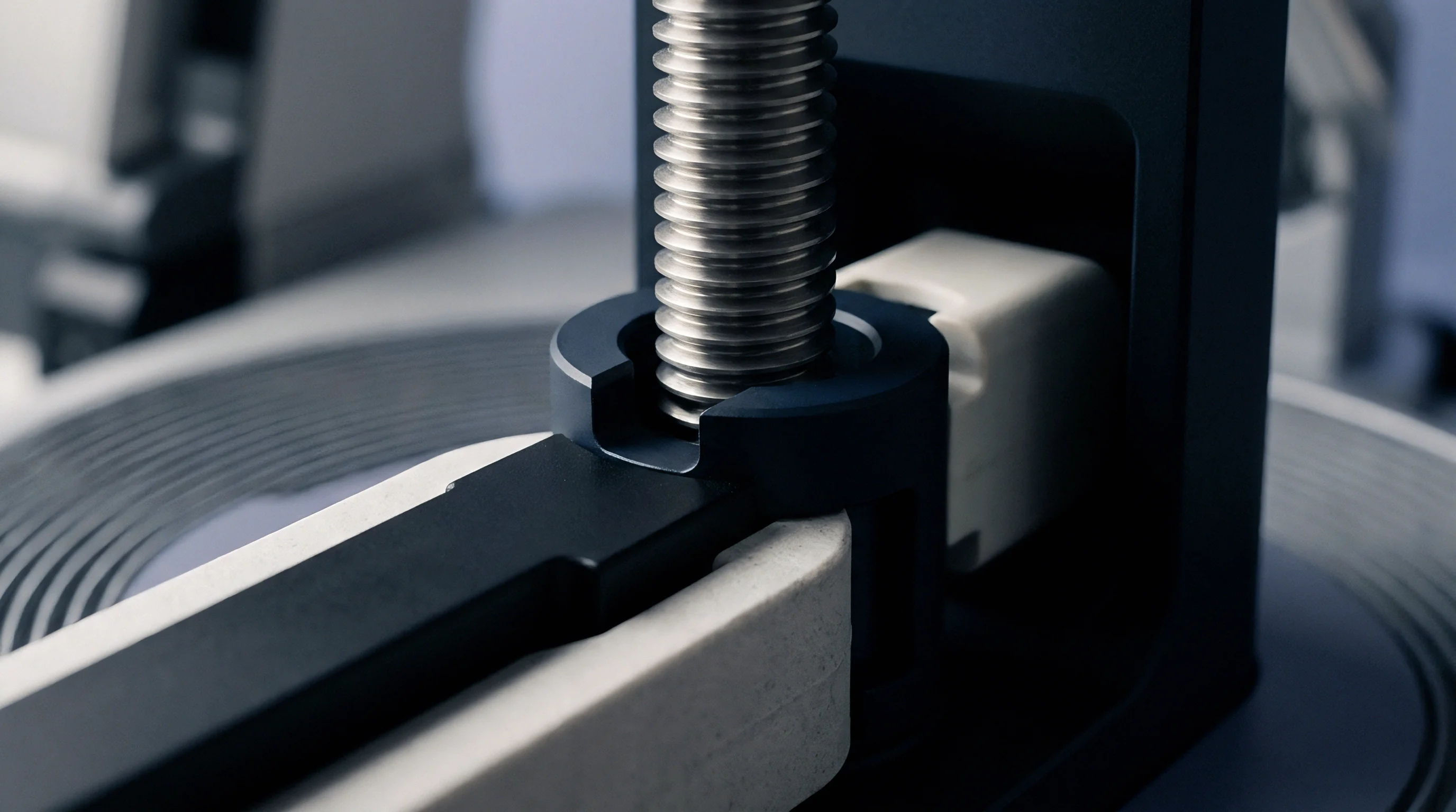
Where Does Thermal Expansion Slip Convert to Residual Stress?
Geometric constraints such as corner radii, return flanges, and vertical stiffener webs prevent planar slip along mold surfaces. At angled geometry transitions, expanding metal tools physically trap composite plies, converting lateral thermal expansion into high localized compressive forces. During post cure dwell holds, trapped corner regions undergo localized matrix deformation while flat sections slip past release coatings.
| Substrate Material | Isotropic CTE (10^-6 / K) | Thermal Conductivity (W/m K) | Tooling Slip Threshold (MPa) | Corner Binding Severity Factor |
|---|---|---|---|---|
| Invar 36 Alloy | 1.2 | 10.5 | 1.8 | Low |
| Monolithic Graphite | 2.0 | 85.0 | 1.2 | Negligible |
| Tool Steel P20 | 12.0 | 29.0 | 4.5 | Moderate |
| Aluminum 6061-T6 | 23.0 | 167.0 | 8.2 | High |
For large-scale structural composite components with steep return angles, maintaining low tooling thermal expansion avoids corner lockup and keeps edge warpage below critical dimensional assembly tolerances.

Strain
Internal force profiles inside cured composite laminates remain invisible until cross-sectional symmetry is disturbed or temperature changes occur. Asymmetry in cure kinetics, thermal gradients, or mechanical boundary constraints generates steep residual stress distributions across the part thickness. These internal forces remain stored within the matrix structure until demolding, where they release instantly as geometric spring-back or out-of-plane distortion.
Shear coupling drives edge distortion.
Resin shrinkage generates early strain gradients.
Layer removal confirms internal stress.

Through Thickness Stress Profiles and Asymmetry
Thermal gradients through the laminate bulk create non-uniform cure kinetics between tool-side plies and bag-side plies. Tool-side plies heat rapidly via direct conduction from the metallic mold, achieving gelation and crosslink density advance before bag-side plies catch up via convection. Resin chemical shrinkage occurring at different times across the thickness creates balanced or unbalanced strain profiles through the laminate cross section.
During post cure dwell holds, constrained boundary conditions lock this asymmetric strain profile in place. When the system cools back to ambient room temperature, differential thermal contraction between plies with varying instant crosslink densities intensifies the internal residual stress profile.
Unbalanced internal stress distributions release upon mold extraction to produce irreversible spring-back and warpage distortions.

Worked Example of Residual Stress Calculation
Consider a sixteen-ply quasi-isotropic carbon fiber epoxy laminate cured on an Invar tool subject to a four-hour dwell at one hundred eighty degrees Celsius. Assume an initial tool-part interface friction coefficient of 0.25 under 0.6 Megapascal autoclave pressure, yielding an interfacial shear stress of 0.15 Megapascals. The laminate thickness measures 2.0 millimeters, with an elastic modulus along the outer ply orientation of 135 Gigapascals.
During the thermal ramp from ambient to dwell temperature, thermal expansion mismatch between Invar (1.2 microstrain per Kelvin) and composite longitudinal plies (0.3 microstrain per Kelvin) across a 160 Kelvin delta drives a free mechanical strain differential of 144 microstrain. Friction forces constrain this slip across a 1.0-meter tool length, building an axial mechanical stress in the lower ply according to boundary equilibrium equations.
The resulting stress calculation follows:
Initial Elastic Strain = Axial Differential Strain = 1.44 x 10^-4
Initial Mechanical Stress = Modulus x Strain = 135,000 MPa x 1.44 x 10^-4 = 19.44 MPa
During the four-hour dwell at one hundred eighty degrees Celsius, viscoelastic stress relaxation follows a single exponential decay model with a relaxation time constant of 1200 seconds (20 minutes). The remaining stress after dwell duration t = 14,400 seconds is evaluated:
Relaxed Stress = Initial Stress x exp(-t / tau) = 19.44 MPa x exp(-14400 / 1200) = 19.44 MPa x exp(-12) = 0.00012 MPa
Because matrix relaxation drops mechanical shear stress virtually to zero during the hold, the tool-constrained geometry establishes a zero-stress reference state at one hundred eighty degrees Celsius. Upon cooling from 180 degrees Celsius to 20 degrees Celsius (delta T = -160 K), the locked composite plies contract without tool friction constraints, re-inducing residual thermal stresses:
Cooling Thermal Strain = Composite Transverse CTE (30 x 10^-6 / K) x (-160 K) = -4.8 x 10^-3
Transverse Thermal Stress = Transverse Modulus (9.0 GPa) x (-4.8 x 10^-3) = -43.2 MPa (Compressive)
This high residual compressive matrix stress along transverse ply orientations remains locked within the part after demolding, driving transverse microcracking risks under service impact loads.

Diagnostic Measurement Techniques
Measuring internal residual strains requires destruction of laminate symmetry or embedding specialized sensor systems directly into the ply stackup during assembly.
- Fiber Bragg Grating Sensors embedded between specific plies measure real-time spectral wavelength shifts to track internal microstrain evolution throughout autoclave cure cycles.
- Incremental Layer Removal measures out-of-plane deflection changes as thin surface plies are systematically machined away from cured composite test coupons.
- Hole Drilling Rosette Method introduces a small precision blind hole into the laminate face to record localized strain relief profiles via multi-axis strain gauge rosettes.
- Curvature Deflection Profiling evaluates radius shifts on unsymmetric test laminates to calculate underlying cross-sectional bending moments.
| Constraint Boundary Condition | Peak Interfacial Shear (MPa) | Relaxed Stress Ratio (%) | Post-Demold Curvature (1/m) | Microcracking Risk Level |
|---|---|---|---|---|
| Fully Constrained Rigid Pins | 28.5 | 98.2 | 0.45 | Severe |
| High Friction Boundary (Mu = 0.35) | 16.2 | 85.4 | 0.28 | Elevated |
| Low Friction Boundary (Mu = 0.05) | 3.1 | 42.1 | 0.08 | Low |
| Unconstrained Free Expansion Slip | 0.2 | 5.0 | 0.01 | Negligible |
Failing to account for constrained stress relaxation during extended high-temperature post cure dwells leads directly to out-of-tolerance structural assemblies, baseline structural microcracking, and premature fatigue failure under working flight loads.


Release
Decoupling the cured laminate from its geometric mold requires precise operational timing to prevent spring-back distortion. Extracting components prematurely while internal temperature remains near glass transition thresholds permits rapid unconstrained creep deformation. Process control protocols must govern exact cooling rates and de-tooling stage gates to maintain final dimensional fidelity.
Early de-tooling introduces geometry drift.
Cooling rates govern final warpage.
Stage Gate Criteria for De Tooling Operations
Quality parameters governing component extraction demand verification of glass transition temperature prior to room temperature cooling. Demolding decisions rely on direct matrix cure state measurements rather than simple thermal timers. Stage gate documentation demands verified differential scanning calorimetry records proving matrix crosslink conversion exceeds ninety-eight percent before mechanical release begins.
Cooling rates from the post cure dwell plateau down to extraction temperatures must not exceed 1.5 degrees Celsius per minute. Rapid cooling generates steep thermal gradients through thick cross sections, inducing transient thermal strains that crack brittle, highly crosslinked matrix structures before tool extraction occurs.
Cost Analysis of Premature Part Extraction
Uncontrolled geometric distortion resulting from early mold removal incurs severe rework expenses and scrap penalties. When high-value aerospace assemblies spring out of tolerance by more than 1.5 millimeters along stiffener attachment flanges, manual shimming or custom machining operations become mandatory during structural integration steps.
Scrapping a primary aerospace wing spar due to uncorrectable spring-back warpage forfeits thousands of dollars in advanced raw carbon materials and consumes critical autoclave machine cycle capacity. Dated process verification protocols ensure every part remains fully constrained until thermal and matrix crosslink conditions reach stability goals.
Quality management provisions in ISO 9001 and AS9100 manufacturing specifications mandate that process stage gates verify complete matrix vitrification prior to structural tool release.