Predictive Finite Element Virtual Unclamping Verification for Nonrigid Semi Crystalline Polymer Part Inspection
Virtual finite element unclamping replaces physical checking fixtures by mathematically correcting free-state optical scans to verify flexible part compliance.


Mold
Thermal gradients across injection mold cavities leave permanent residual stress profiles in semi-crystalline polymers. Because core and cavity surfaces cool at different rates, local crystalline phase transformations shift polymer density from an amorphous one point fourteen grams per cubic centimeter to a semi-crystalline one point twenty-two grams per cubic centimeter. Polymer chains align along melt flow vectors, driving anisotropic thermal expansion coefficients that can differ by up to three hundred percent between parallel and transverse directions.
When a thin-walled part ejects from the mold, these internal stresses relax into free-state geometric distortion ~ warpage, bow, and twist that pull features away from nominal CAD geometry.
Conventional dimensional inspection relies on heavy aluminum or steel clamping fixtures to force flexible plastic components against rigid datum blocks. Mechanical clamps, hydraulic toggles, or vacuum nests flatten the part into nominal shape before tactile probing on a CMM or laser line scanning takes place. That physical clamping forces elastic deflection, masking real manufacturing variability.
A component certified as fully compliant inside a rigid fixture often generates excessive bolt-hole forces, localized buckling, or joint gap failures once fastened to its mating assembly on the production line.
Injection Morphology and Free State Deflection
Phase transformations during solidification dictate the final geometry of thin-walled moldings. Resins like polyphthalamide, polyphenylene sulfide, and glass-reinforced polyamides exhibit uneven shrinkage driven by gate locations, melt temperature drops, and mold cooling layout. Core regions cool more slowly than outer skin layers, locking high tensile residual stress into the center while outer surfaces remain under compression.
As soon as the mold opens, these internal stress gradients release, causing elastic springback that distorts the part in its free state.
Measuring a clamped flexible component records the geometry of the steel fixture rather than the quality of the polymer molding process.
Evaluating glass-filled polyphthalamide engine covers across different tool heating setups demonstrates the extent of free-state geometric drift. Optical photogrammetry showed that shifting mold temperatures from eighty degrees Celsius to one hundred twenty degrees Celsius caused up to four point two millimeters of free-state warpage over a six hundred millimeter span. Under standard inspection routines, mechanical toggle clamps pressed these covers flat against datum pads, concealing the bow completely and returning profile tolerances well inside the zero point five millimeter drawing limit.
Subsequent engine bay trials showed flange lift and oil seal leakage during thermal cycling.
Relying on physical inspection fixtures introduces clear failure modes when evaluating nonrigid semi-crystalline moldings:
- Fixture Induced Deformation Toggle clamp forces permanently deform local plastic geometry, producing false acceptance data that masks real part variation.
- Datum Surface Flattening Clamping pressure against datum pads irons out sink marks and cavity warpage, leaving toolmakers without the data needed to diagnose thermal imbalances.
- Over-Constraint Masking Rigid multi-point clamping hides residual stress fields that later relax under operating temperatures, leading to assembly distortion in the field.
- High Tooling Expenditure Dedicated checking gages add forty thousand to one hundred twenty thousand dollars per part number in capital tooling expense.
Optical Scanning Constraints in Flexible Polymers
Structured light projectors and blue laser line scanners digitize nonrigid plastic parts unrestrained, without physical contact. High-resolution sensors record millions of surface coordinates, generating dense polygon meshes that capture the true free-state boundary. Free-state scanning captures raw thermal warpage without mechanical distortion, establishing an accurate baseline for geometric inspection.
Evaluating free-state data directly against engineering drawings creates its own inspection challenges. Callouts under ISO 10579 or ASME Y14.5 define nonrigid part dimensions in a restrained or assembled state. An unconstrained optical scan of a semi-crystalline part will frequently exceed geometric profile tolerances by three hundred to six hundred percent.
Without inverse numerical modeling, quality inspectors cannot tell whether a warped part will pull into tolerance when bolted down or whether the required clamping force will crack the mounting bosses.
Out-of-spec free-state dimensions do not necessarily indicate an incorrectly cut mold cavity, as semi-crystalline moldings require assembly restraint to reach nominal geometry.


Mesh
Numerical simulation of nonrigid bodies requires spatial discretization that captures local curvature accurately. Triangulating point clouds from optical 3D scanners produces dense surface meshes of three-node linear or six-node quadratic triangular shell elements. Mesh sizing must balance local feature resolution against solver run times, holding edge lengths between zero point five millimeters around tight fillets and five millimeters across flat sections.
Virtual unclamping routines invert standard structural FEA procedures. The algorithm takes the free-state scanned mesh, assigns nonrigid constitutive material properties, and applies displacement boundary conditions that draw defined datum points into zero-displacement contact with CAD datums. By evaluating reaction forces and strain energy density throughout the mesh, the solver can mathematically unclamp restraints to predict free-state geometry or calculate internal assembly strains.

Mathematical Formulation of Reverse Displacement Boundary Conditions
Governing equations for nonrigid virtual clamping balance internal elastic strain energy against external constraint forces. Let the vector field represent spatial coordinates of the unconstrained, scanned mesh. Nonlinear structural solvers determine the displacement vector required to map free-state surface coordinates onto target fixture or assembly datums using the global stiffness formulation:
Inverting this system lets engineers solve for the residual deviation vector field once virtual restraint forces reach equilibrium. Nonlinear geometric terms, defined via the Green-Lagrange strain tensor, capture large rotational deflections in thin-walled sections without introducing artificial numerical stiffening.
An engineering drawing containing the ISO 10579 nonrigid indicator requires specification of maximum allowable restraint forces alongside spatial tolerance zones.
Convergence depends on proper characterization of material nonlinearity, boundary conditions, and contact stiffness. Mid-surface shell element formulations keep solve times manageable while preventing shear locking in thin-walled semi-crystalline parts.
| Polymer Matrix Grade | Fiber Mass Fraction (%) | Parallel Modulus (MPa) | Perpendicular Modulus (MPa) | Hygroscopic Strain Coefficient (%/% H2O) | Core Crystallinity (%) |
|---|---|---|---|---|---|
| PA66 Standard Molded | 0 | 3100 | 2800 | 0.28 | 38.5 |
| PA66 Glass Reinforced | 30 | 9500 | 4800 | 0.19 | 42.0 |
| PPA High Thermal | 40 | 13800 | 6200 | 0.08 | 46.2 |
| PBT Structural Grade | 30 | 9800 | 5100 | 0.02 | 39.8 |
| PPS Reinforced Matrix | 40 | 15200 | 7400 | 0.01 | 54.0 |

Anisotropic Constitutive Tensors and Material Matrix Integration
Fiber-reinforced semi-crystalline polymers show marked directional differences in elastic modulus, Poisson’s ratio, and shear modulus. Mold filling simulations export orientation tensor components across each element layer. Micromechanical models, including Mori-Tanaka or Eshelby formulations, convert these fiber orientation tensors into local orthotropic stiffness matrices for structural analysis.
Assuming isotropic properties introduces significant error into virtual unclamping calculations. Using a single elastic modulus across a glass-filled polyamide component causes inverse solvers to miscalculate clamp reaction forces by twenty to forty-five percent. Areas with high longitudinal fiber alignment are up to three times stiffer than transverse regions, altering predicted springback vectors when virtual clamps release.
Numerical instability occurs in inverse solvers whenever shell thickness varies by more than six percent across unreinforced transition zones, leading to local mesh distortion during displacement mapping.
Errors in spatial discretization and solver setup generally stem from a few common modeling oversights:
- Isotropic Modulus Simplification Applying scalar stiffness values to fiber-reinforced polymers skews clamping strain energy and yields incorrect springback calculations.
- Coarse Feature Triangulation Large triangular elements fail to resolve tight radii, creating artificial stress concentrations at virtual clamp locations.
- Linear Geometric Assumptions Leaving out second-order geometric terms causes artificial volume expansion during large-deflection bending calculations.
- Unconstrained Rigid Body Modes Missing kinematic restraints lead to singular stiffness matrices and solver crashes during inversion routines.
Mesh resolution at localized clamp contact zones governs convergence stability during non-linear inverse contact modeling.

Clamp
Traditional CMM checking fixtures secure flexible moldings against rigid datum blocks. Virtual clamping replaces steel locators, hydraulic toggles, and vacuum cups with numerical kinematic restraints applied directly within structural FEA software. Setting up virtual locators under a standard six-point scheme locks down rigid body motion without creating false over-constraint stresses.
Kinematic restraint schemes align the scanned free-state mesh to nominal CAD datums: primary locators establish the plane, secondary locators fix orientation, and tertiary locators lock the origin. Numerical contact routines handle surface interaction between virtual clamp pads and the deformed mesh, replicating physical gage closure in software.

Does Fixture Restraint Force Mask Dimensional out of Roundness?
Heavy mechanical clamping on cylindrical or curved parts routinely conceals roundness errors. Clamps readily squeeze thin-walled circular flanges into round alignment against locator rings, hiding severe asymmetric shrinkage. Once taken off the fixture for vehicle assembly, stored elastic strain causes the part to ovalize, misaligning mating interfaces.
Virtual unclamping algorithms calculate the exact force vectors applied by each virtual clamp pad during numerical restraint. If the computed clamping force exceeds manual assembly limits, the software flags the part as out of specification, even if its clamped profile meets drawing tolerances. Monitoring virtual reaction forces provides a direct check on part flexibility and locked-in strain.
| Boundary Condition Type | Solver Algorithm | Penalty Stiffness (N/mm) | Friction Coefficient | Iterative Steps | Convergence Time (s) |
|---|---|---|---|---|---|
| Kinematic 3-2-1 Pins | Direct Lagrange | Infinite | 0.00 | 1 | 12.4 |
| Surface Vacuum Pad | Penalty Method | 1e5 | 0.20 | 14 | 142.8 |
| Hydraulic Toggle Clamp | Augmented Lagrange | 1e6 | 0.15 | 22 | 210.5 |
| Over-Constrained Rail | Penalty Method | 5e4 | 0.25 | 38 | 485.0 |

Kinematic Datum Placement and over Restraint Resolution
Over-constrained physical fixtures load parts at redundant contact points, forcing flexible moldings into artificial alignment. Drawings for large automotive panels often call out more than six datum points to replicate multi-fastener joints. Virtual clamping models evaluate these multi-point setups by solving contact conditions through non-linear penalty or Lagrange multiplier methods.
Accurate virtual contact modeling requires realistic interface friction coefficients. Semi-crystalline polymers sliding against polished steel locators exhibit friction coefficients between zero point fifteen and zero point thirty. Omitting contact friction lets mesh nodes slide unrealistically across datum blocks, underestimating shear strains and shifting post-unclamp displacement predictions.
An unverified physical gage distorted a thin-walled assembly during early tool qualification, incurring a forty-two thousand dollar fixture remachining charge. Running virtual unclamping beforehand avoids these rework costs by proving out locator schemes prior to cutting steel.
Setting up virtual fixtures requires working through a clear sequence of diagnostic checks:
- Scan Mesh Validation Inspect the raw free-state mesh for open boundaries, overlapping elements, or scan noise before applying reference frames.
- Datum Kinematic Definition Set primary, secondary, and tertiary virtual locators to match drawing datums and eliminate all six rigid-body degrees of freedom.
- Contact Friction Parameters Apply measured sliding friction values for polymer-to-metal contact to capture shear strains accurately.
- Reaction Force Auditing Check calculated virtual clamp forces against assembly limits to catch excessive internal strain early.
Evaluating virtual fixture setups on complex multi-curved moldings highlights the necessity of tracking strain energy density across unconstrained surface regions.


Strain
Deformation observed during free-state optical scanning reflects the combined effect of residual stresses and environmental exposure. Semi-crystalline polymers ~ polyamides in particular ~ take on ambient moisture over time, which plasticizes the matrix and causes hygroscopic swelling. Conformance checks on nonrigid parts must separate mold-induced thermal warpage from post-ejection moisture uptake and viscoelastic stress relaxation.
Predictive finite element unclamping incorporates ambient environmental factors into the inverse solver. Updating the constitutive material tensor for moisture content and temperature ensures that calculated clamping forces reflect actual production conditions. Modeling stress relaxation also provides insight into long-term creep under continuous bolt preloads.

Worked Comparative Inspection Routine for Automotive Battery Carrier
A structural battery carrier molded in thirty percent glass-filled polybutylene terephthalate measured twelve hundred millimeters long by four hundred fifty millimeters wide, with a nominal wall thickness of two point eight millimeters. Drawing specifications called for a free-state surface profile tolerance of one point two millimeters across all mounting faces, tightening to zero point five millimeters when constrained to CAD datums per ISO 10579.
Physical inspection on a CMM using pneumatic toggle clamps returned passing surface profile results, averaging zero point thirty-two millimeters. Yet on the assembly line, operators ran into severe bolt-hole misalignment and cracked primary mounting bosses during automated rundown. Physical clamping had pressed the flexible baseplate flat against the gage pads, completely concealing a three point eight millimeter diagonal bow in the unrestrained molding.
Using an optical scanner, metrologists captured two million six hundred thousand surface nodes from the unconstrained carrier in a temperature-controlled lab. That surface mesh was imported into a nonlinear inverse FEA solver. Anisotropic material properties were assigned using fiber orientation data from mold filling simulations, setting local moduli to nine thousand eight hundred megapascals parallel to flow and five thousand one hundred megapascals transverse to flow.
Virtual clamps pulled the scanned mesh onto nominal CAD datums, solving the geometric nonlinear displacement field. The inverse solver calculated that forcing the part onto the forward left mounting boss required four hundred eighty-five newtons of clamping force. That far exceeded the ninety newton manual assembly limit and generated local tensile strains of two point eight percent, surpassing the yield point of the reinforced resin.
| Datum Inspection Feature | Nominal CAD Position (mm) | Physical CMM Clamped (mm) | Raw Unrestrained Optical Scan (mm) | FEA Virtual Unclamped Value (mm) | Virtual Clamp Force Vector (N) |
|---|---|---|---|---|---|
| Primary Mount Boss A1 | 0.00 | +0.04 | +3.82 | +0.12 | 485.0 |
| Secondary Mount Boss A2 | 0.00 | -0.02 | +2.15 | -0.08 | 210.0 |
| Lateral Locator B1 | 0.00 | +0.01 | -1.45 | +0.05 | 65.0 |
| Corner Rib Base C1 | 0.00 | +0.08 | +4.10 | +0.42 | 310.0 |
| Center Structural Rail | 0.00 | +0.15 | +5.25 | +0.88 | 540.0 |
Rebalancing the mold cavity cooling circuits reduced the unconstrained diagonal bow to one point six millimeters. A repeat virtual unclamping run showed that required assembly clamp forces dropped to forty-two newtons, bringing post-unclamp profile deviations down to zero point thirty-six millimeters ~ comfortably inside the drawing tolerance.

Hygrothermal Relaxation and Environmental Drift Corrections
Polyamides absorb ambient moisture until reaching equilibrium, altering both part dimensions and structural stiffness. A glass-filled PA66 part scanned right after molding shows high stiffness and negligible moisture expansion. After seventy-two hours at fifty percent relative humidity, moisture uptake reduces the elastic modulus while swelling dimensions by up to zero point three percent.
Virtual unclamping models account for hygrothermal drift by adjusting the constitutive matrix according to part conditioning history. Adding a hygroscopic expansion strain tensor to the solver separates thermal warpage from ambient swelling, preventing the false rejection of parts inspected immediately after molding.
Tracking dimensional change across varying humidity levels over twenty-eight days confirmed that virtual unclamping predictions matched physical equilibrium geometry within zero point zero five millimeters once moisture coefficients were incorporated into the FEA model.
Setting up an inverse virtual unclamping routine follows a standard computational workflow:
- Capture high-density point clouds of the unconstrained molding with a calibrated 3D optical scanner in a temperature-controlled metrology lab.
- Export polygon mesh files, cleaning out scan fixtures, optical reflections, and surrounding background data.
- Import the mesh into structural FEA software, checking mesh watertightness and verifying surface normal vectors.
- Assign anisotropic constitutive matrices to the mesh using fiber orientation data exported from validated mold filling models.
- Define kinematic virtual boundary conditions matching drawing datums and clamping locator positions.
- Solve the nonlinear geometric equilibrium equations to calculate displacement vectors and constraint reaction forces.
- Mathematically release the virtual restraints to output corrected dimensional deviations and residual internal strain distributions.
- Evaluate the resulting virtual deviation data against drawing tolerances to accept or reject the production lot.
Virtual verification accuracy increases when material card inputs mirror actual ambient storage history prior to optical scan acquisition.

Dossier
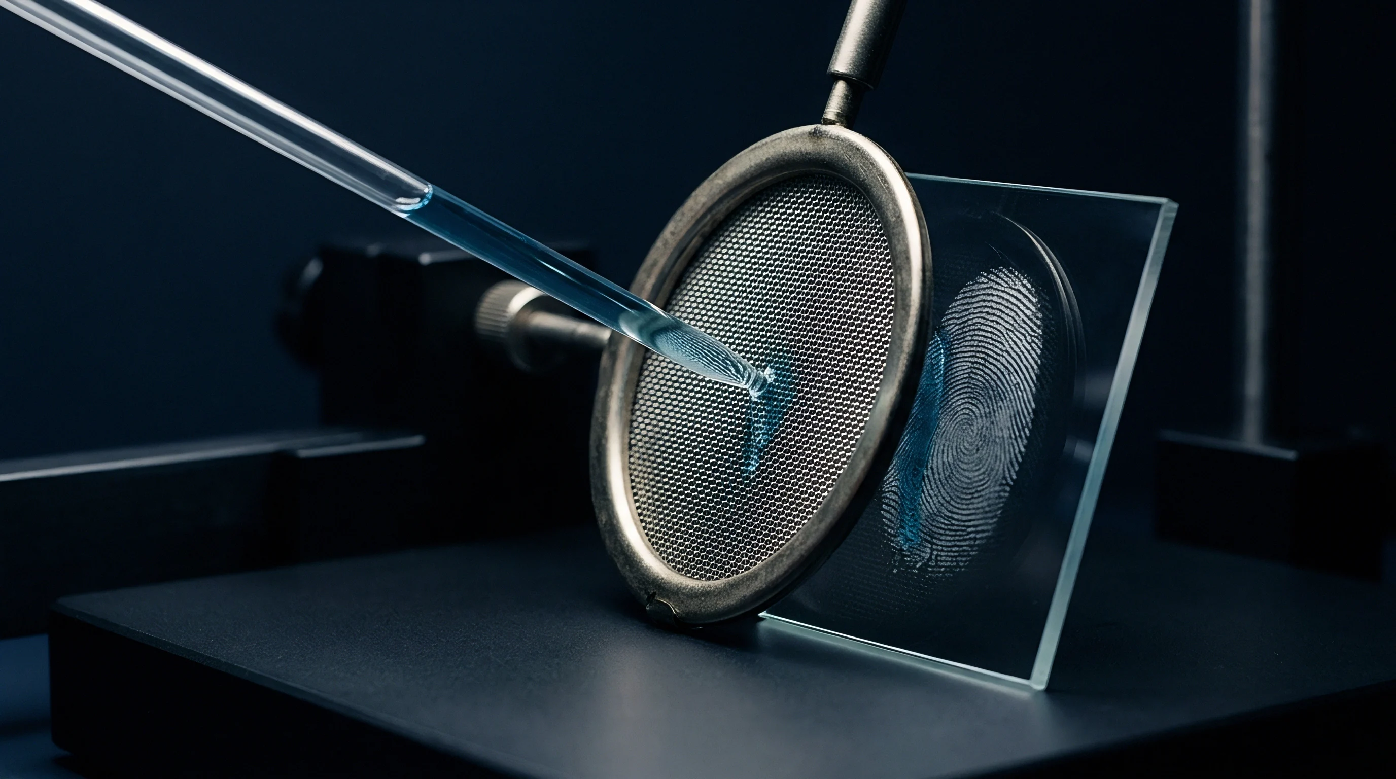
Quality management systems require clear, traceable documentation before releasing production tooling. Moving from physical checking gages to virtual unclamping verification requires updating supplier quality standards, initial sample inspection reports, and tool sign-off procedures. Standardizing digital verification methods ensures that suppliers and OEMs evaluate nonrigid components using identical criteria.
Tooling purchase agreements should outline virtual verification deliverables alongside standard part acceptance metrics. Requiring suppliers to provide validated scan meshes, fiber orientation maps, and virtual unclamping reports turns part qualification into an objective, data-backed review rather than a subjective dispute over gage fit.
Commercial Qualification and Quality Assurance Integration
Adding virtual unclamping simulations to PPAP workflows replaces dedicated checking fixtures with digital verification dossiers. Capital spending shifts from physical gage builds to optical scanning cells and FEA simulation seats. Removing dedicated check gages shortens tooling lead times by six to ten weeks per program.
Tooling contracts must define boundary conditions, clamping force thresholds, and solver convergence criteria explicitly. Vague simulation requirements allow suppliers to manipulate virtual outputs ~ whether by inflating material stiffness or leaving out contact friction ~ hiding true part defects during initial sample submissions.
Replacing physical checking fixtures with inverse finite element virtual unclamping routines reduces capital tooling expenditure while shortening program launch timelines by two months.
Stage Gate Protocols for Tooling Acceptance
Tool acceptance workflows rely on structured stage gates tied directly to digital verification milestones. Phase one assesses cavity steel accuracy using unrestrained optical scans. Phase two runs virtual unclamping simulations to verify assembled geometry and clamp force limits.
Phase three signs off on final tool release once physical trial builds confirm simulation predictions within defined confidence windows.
Quality records should retain raw point cloud files, material property input cards, and solver run files alongside final inspection certificates. Archiving full simulation packages allows teams to re-evaluate part compliance during engineering changes or field failure root-cause investigations without building new checking fixtures.
Standard quality compliance guidelines dictate that supplier initial sample inspection reports carry certified virtual verification dossiers whenever nonrigid drawing callouts govern part geometry:
Section 4.3 of Automotive Quality Protocol IATF 16949 compliant supplier agreements stipulates that dimensional evaluation of nonrigid components specified under ISO 10579 must provide documented finite element virtual unclamping verification reports, including calculated reaction force vectors and validated fiber orientation inputs, prior to final tooling capital release.