Auxiliary Utility Capacity Verification in Machining Cell Expansion
Verifying dynamic peak auxiliary utility headroom before capital commitment prevents localized pressure collapses, thermal tripping, and machining cell expansion stalls.


Surge
Transient demand spikes routinely destabilize production lines when utility expansions are sized against nameplate averages. Bringing a new machining cell online adds pneumatic, electrical, and hydraulic loads that hit the plant grid simultaneously rather than distributing evenly over a shift. Spindle acceleration, tool clamping, high-pressure coolant pumps, and chip washdown cycles all create brief, aggressive demand spikes.
When multiple machines enter high-draw cycles at the same instant, local air pressure drops and supply voltage sags. Shift-wide averages conceal these brief surges, leaving plants to troubleshoot unexplained machine alarms, drive faults, and part dimension drift.
Catching transient overlap requires measuring high-frequency peak loads rather than analyzing monthly utility bills. A cell of four five-axis machining centers may average sixty cubic feet per minute of compressed air over a shift, yet surge to two hundred forty cubic feet per minute for three seconds during a simultaneous tool change and part blow-off. If distribution lines and local receiver tanks are sized for average consumption, pressure at the machine regulator drops below the threshold required to hold the spindle drawbar open.
The machine then trips on a fault code that technicians frequently misdiagnose as a mechanical failure. Dynamic load profiling captures these true peak draws across every auxiliary drop.
Severe utility fluctuations directly compromise spindle position accuracy and surface finish.
Calculating coincidence factors depends on mapping how auxiliary cycles overlap across the cell. The calculation itself is simple: the ratio of peak combined demand to the sum of individual peak demands. For a single machine, this factor is one.
Planning calculations often assume the factor drops as machines are added, relying on statistical variance in cycle timing. In automated or synchronized cells operating on fixed takt times, however, cycles lock into step. This phase synchronization aligns auxiliary draws and pushes the real coincidence factor back toward unity.
| Cell Configuration | Electrical Peak Multiplier | Pneumatic Peak Multiplier | Coolant Peak Multiplier | Observed Coincidence Factor |
|---|---|---|---|---|
| Single 5-Axis Cell | 1.85 x Continuous | 2.40 x Continuous | 1.15 x Continuous | 1.00 |
| Dual Cell Unsynchronized | 1.60 x Continuous | 2.10 x Continuous | 1.15 x Continuous | 0.78 |
| Quad Cell Takt Synchronized | 1.80 x Continuous | 2.35 x Continuous | 1.25 x Continuous | 0.92 |
| Eight Cell Automated Line | 1.75 x Continuous | 2.20 x Continuous | 1.30 x Continuous | 0.88 |
Auxiliary utility bottlenecks are the primary cause of project delays during machining cell expansions. Project teams often proceed assuming existing distribution headers have ample spare capacity. While central compressors or sub-stations may show unused nominal horsepower or kilovolt-ampere capacity, plant evaluations frequently overlook branch piping layouts and busway tap boxes.
A compressor room might have two hundred cubic feet per minute of spare volume, but a two-inch drop leg feeding the new cell can drop fifteen psi the moment three blow-off nozzles trigger together. Dynamic losses within local branches ultimately dictate machine performance.
A plant expansion sizing its utility supply against average electrical and fluid draw experiences pressure drops and thermal tripping during synchronized shift starts.
Available utility capacity is ultimately determined by peak demand rather than average consumption.
Unmeasured transient spikes risk line shutdowns. Evaluating machining cell expansion plans requires rigorous empirical testing of utility capacity under fully simulated coincidence conditions. Static models consistently miss dynamic pressure losses.
Validation testing must run every auxiliary pump, chiller compressor, exhaust fan, and pneumatic actuator simultaneously at maximum operational rates. Measuring supply pressure at the machine inlet fitting under full load separates branch piping restrictions from central supply limits, establishing the baseline needed to decide whether local piping requires upgrading.
Sizing main utility headers by multiplying total nameplate connected load by static usage factors leads to severe pressure drops and fluid starvation during coincident spindle starts.

Sump
Central coolant systems fail primarily from hydraulic starvation or thermal overload when added machinery exceeds return flume capacity. Higher delivery rates at cutting zones mean swarf must be cleared far more quickly. High-pressure units force fluid through tooling at up to seventy bar, generating heavy return flows that must drain cleanly back to the filtration tank.
Gravity flumes and floor trenches rely on precise channel slopes and flow velocities to carry chips; connecting too many machines increases fluid drag and chip volume, turning the channel into a settling basin that chokes return flow.
High-pressure coolant pumps transfer substantial heat directly into the fluid. Positive displacement designs convert mechanical work into thermal energy, where a single seventy-bar pump running continuously adds over fifteen kilowatts to the reservoir. Connecting four such units to an existing central sump places heavy demand on plant chillers.
If chilling capacity falls behind, rising fluid temperatures cause machine castings to expand, driving workpieces out of tolerance while accelerating oxidation that degrades coolant chemistry.
Unchecked heat buildup causes machine castings to expand and drift out of tolerance.
Friction within supply headers significantly reduces delivery pressure over long distribution runs. As cell expansions increase flow demand, fluid velocity inside supply lines rises. Pipe friction increases non-linearly with velocity, causing major pressure drops between the central pump and machine connections.
If supply pressure falls below two bar at the inlet, flood coolant loses the momentum required to clear chips from deep cavities, triggering low-pressure machine alarms.
| Parameter | Minimum Threshold | Target Operating Range | Maximum Limit | Failure Indicator |
|---|---|---|---|---|
| Flume Return Velocity | 0.8 m/s | 1.2 – 1.5 m/s | 2.2 m/s | Swarf Settling in Channel |
| Coolant Temperature | 18 deg C | 20 – 22 deg C | 25 deg C | Workpiece Thermal Expansion |
| Header Delivery Pressure | 2.5 bar | 3.5 – 5.0 bar | 8.0 bar | Low Flow Machine Alarms |
| Filter Bed Flow Velocity | 0.01 m/s | 0.02 – 0.03 m/s | 0.05 m/s | Filter Fines Bypass |
Filter surface area determines how effectively return fluid is cleaned. Disposable media rolls and vacuum drum filters process coolant at fixed flux rates, measured in gallons per minute per square foot of media. Increasing pump output without expanding filter surface area forces fluid through the media too rapidly.
The elevated differential pressure pulls fine metal particles through the bed, recirculating abrasive swarf into high-pressure pumps and spindle tooling. Premature pump wear and scored seals usually trace directly to excessive flow velocity across the filter.
High pressure coolant units operating at seventy bar generate thermal loads that exceed static cabinet chiller ratings when spindle duty cycles pass eighty percent.
Evaluating fluid systems prior to capital commitment requires examining every hydraulic element along both supply and return circuits.
- Return Flume Slope Decay occurs when facility floor settling reduces channel angle, lowering fluid velocity and settling heavy chips inside underground troughs.
- Chiller Thermal Saturation happens when auxiliary heat loads from high-pressure pumps exceed heat exchanger BTU ratings, driving fluid temperatures past thirty degrees Celsius.
- Filter Media Blinding results from high particulate loading during continuous heavy milling, causing frequent index cycles and excessive media consumption.
- Cavitation at Pump Suction arises when return fluid flow drops below pump displacement capacity, drawing air bubbles into coolant lines and destroying pump impellers.
Supply pumps require adequate fluid volume at the intake to prevent cavitation.
Plant engineers routinely size central sump capacities based strictly on volumetric hold-up times. Maintaining a reservoir volume ten times the pump rating per minute is standard practice, but it proves inadequate for cells running high-pressure coolant. Fluid held inside machine enclosures, carried away on chip conveyors, or suspended in long overhead lines reduces active sump volume.
During operation, three hundred liters can remain in transit before returning to the pit. This dynamic drawdown starves pumps at shift startup before return flows equalize, making fluid volume verification during live production essential.
Ignoring fluid velocity limits in return flumes leads to chip buildup, pump starvation, accelerated tool wear, and unexpected downtime across all connected machines.

Duct
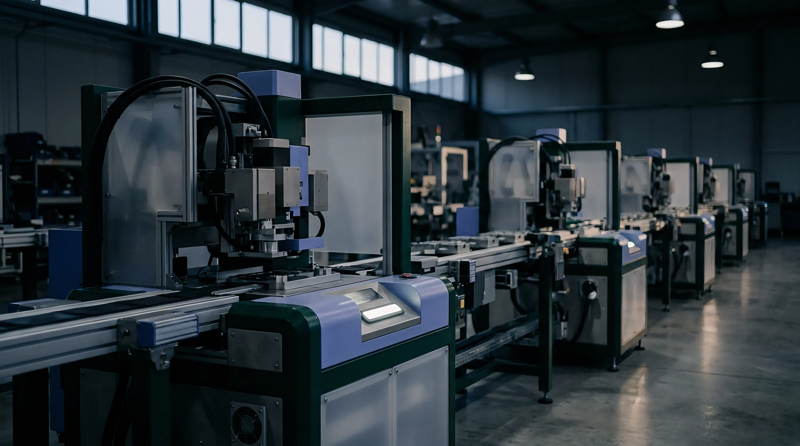
Compressed air headers and mist extraction ducts both suffer sharp pressure drops during simultaneous valve operations. Machining cells draw compressed air for spindle purge air, tool blow-off jets, part seating sensors, and workholding clamps. Unlike electrical power, pneumatic delivery relies on physical air volume moving through tight fittings and narrow internal passages.
Adding automated fixtures raises continuous air demand while doubling peak surge volume. A supply header running at seven bar can drop to four bar if three clamps and two spindle blow-offs actuate at the same time.

Where Does Air Pressure Collapse during Simultaneous Tool Changes?
Tool changer blow-off nozzles draw directly from local accumulators, rapidly depleting branch pressure if receiver tanks are undersized. The primary restriction typically occurs in the final drop lines and filter-regulator-lubricator units at the machine inlet. Standard half-inch drop lines cannot supply eighty standard cubic feet per minute for an automated tool blast without losing two bar across the fitting.
Part seating sensors register this drop immediately, faulting the machine with false misclamp errors during part loading.
Undersized distribution headers fail to deliver required air volume during multi-valve actuation.
Pneumatic pressure loss follows standard fluid mechanics: frictional resistance scales with the square of volumetric flow rate. Doubling air velocity through a pipe quadruples the pressure drop. Connecting new cells to existing branch lines frequently exceeds recommended flow speeds.
Air velocity in distribution runs should remain under six meters per second; exceeding fifteen meters per second generates high turbulence, steep pressure losses, and pulls pipe condensate straight into delicate machine valves.
ISO 8573 class two air purity specifications mandate dedicated desiccant drying headers when expanding sub-spindle blow-off networks to prevent pneumatic actuator fouling.
Mist extraction systems present distinct balancing challenges. Higher spindle speeds produce finer coolant mist, requiring duct velocities between twelve and fifteen meters per second to carry droplets to central collectors without oil pooling in horizontal ducting. Oversizing ducts without balancing airflow drops velocity below transport thresholds, letting oil collect in low points to create structural weight and fire hazards.
Conversely, tapping new intake branches without increasing fan static pressure starves existing drops, leaving enclosures filled with coolant vapor.
Temperature variations in tooling and fluid continuously affect tight machining tolerances.
Vacuum workholding operates on identical flow principles. Clamping force depends on maintaining low absolute pressure at the fixture, while machining porous castings requires extra pump capacity to offset air drawn through internal material voids. If vacuum pump CFM fails to outpace leakage during clamping, holding force degrades during heavy roughing cuts.
Properly sizing vacuum systems requires testing dynamic airflow against vacuum depth across the full range of material porosity.
Equipment vendors often attribute line pressure drops to plant supply fluctuations rather than flow restrictions within their own internal valve manifolds.
Phase
Electrical supply equipment serving automated cells experiences significant thermal and harmonic stress as variable frequency drives accumulate. Spindle motors, servo drives, high-pressure pumps, and chip conveyors draw power in rapid pulses rather than continuous sine waves. This non-linear current draw injects harmonic distortion into plant transformers and busways, increasing electrical losses, overheating neutral conductors, and causing nuisance trips on sensitive breakers.
High harmonic distortion accelerates transformer heating and shortens insulation life.
Transformer kVA ratings assume pure sinusoidal loads. When variable frequency drives account for most of the demand, transformers must be derated using K-factor calculations to prevent insulation damage from eddy current heating. A standard transformer loaded to eighty percent capacity with a fifteen percent harmonic distortion profile operates at its thermal boundary.
Adding two multi-axis machining centers to that busway elevates winding temperatures past design limits, accelerating insulation breakdown and triggering unexpected sub-station outages.
| Expansion Scale | Busway Amperage Capacity | Total Harmonic Distortion limit | Voltage Unbalance Maximum | Required Transformer K-Factor |
|---|---|---|---|---|
| Base Cell (2 Machines) | 400 A | 3.5 percent | 0.8 percent | K-4 |
| Expanded Cell (4 Machines) | 800 A | 6.2 percent | 1.2 percent | K-9 |
| Expanded Cell (8 Machines) | 1600 A | 9.8 percent | 1.8 percent | K-13 |
| High-Speed Automated Line | 2000 A | 12.5 percent | 2.1 percent | K-20 |
Voltage imbalance in three-phase distribution lines causes severe motor overheating. An imbalance exceeding one percent induces negative-sequence currents in fixed-speed induction motors powering hydraulic units and chillers. At a two percent imbalance, motors must be derated to ninety-five percent of rated output.
Connecting new machining cells to unbalanced lines results in overheated pump motors and frequent thermal overload tripping.
Verifying available electrical capacity requires a systematic evaluation of the distribution infrastructure.
- Install a calibrated power quality analyzer at the main busway feed box for a continuous seven-day production cycle.
- Log peak root-mean-square current, instantaneous voltage sags, and total harmonic voltage distortion at ten-millisecond intervals.
- Calculate current harmonic spectrum components up to the fiftieth harmonic order during heavy roughing operations.
- Determine existing transformer thermal margin using k-factor calculations based on recorded harmonic current profiles.
- Model projected voltage drop along extended busway runs incorporating total combined expanded cell peak current draw.
Long-term power quality logging captures peak electrical loads that snapshot checks miss.
Transformer temperature rises exponentially when total harmonic distortion from variable frequency drives exceeds eight percent under continuous heavy milling loads.
Power factor penalties increase when multi-axis drives draw significant reactive current. Displacement power factors below zero point nine zero incur utility charges while reducing available switchgear capacity. Installing standard power factor correction capacitors without detuning reactors forms resonant circuits with drive inductances, amplifying harmonic currents and failing capacitor units.
Any system expansion must confirm harmonic filter compatibility prior to installing capacitor banks.
Standard ISO 8528 and IEEE 519 provisions in equipment contracts assign financial responsibility for power conditioning to the machinery vendor whenever non-linear loads push total harmonic distortion past contract limits.
Dossier
Measured verification data provides the only sound basis for confirming utility capacity before approving capital expenditure. Evaluating system readiness requires assembling historical telemetry, high-speed pressure logs, and utility audit records into a verified documentation package. Assumptions regarding spare capacity must be replaced with physical measurements taken during peak production.
A thorough audit exposes discrepancies between facility drawings and actual floor delivery.
As-built piping and instrumentation drawings rarely reflect undocumented taps, pipe reductions, or dead-legs added over time. Physical verification must confirm pipe diameters against system schematics. On compressed air mains, ultrasonic thickness testing reveals scale buildup, internal corrosion, and restricted passages that throttle flow.
The final audit dossier must document dynamic pressure under full production load rather than relying on static pressure readings taken while machines are idle.
Utility capacity verification requires auditing specific physical and operational parameters across every auxiliary line before committing capital funds.
- High-Frequency Transducer Data Logs recording pressure and flow fluctuations at one-hundred-Hertz sampling rates isolate micro-surges during tool change sequences.
- Thermal Imaging Logs of electrical switchgear, busway tap boxes, and transformer terminals identify phase imbalance and loose high-resistance connections under full load.
- Fluid Velocity and Viscosity Records confirming coolant return channel transport capability prevent chip settling and channel overflowing.
- Coolant Chiller Heat Exchanger Test Certificates proving total British Thermal Unit heat extraction capacity under maximum ambient shop temperatures validate thermal dissipation margins.
- Water Quality and Conductivity Reports for closed-loop cooling systems prevent heat exchanger scaling and biological fouling that degrades chiller efficiency.
Pressure drops in branch lines frequently interrupt automatic tool changing cycles.
Discrepancies between manual nameplate ratings and actual power draws account for significant post-startup downtime. Equipment builders publish utility consumption based on standard machining cycles, but heavy roughing in titanium or aerospace alloys can exceed published ratings by forty percent during sustained cuts. Recording real-time telemetry from identical machines running similar operations yields the only accurate baseline for utility modeling.
Data accuracy depends on calibrating sensors before gathering diagnostic records. Uncalibrated flow meters and pressure transducers produce misleading capacity profiles that result in poor engineering decisions. Verification packages must include calibration certificates, logging period records, and documentation of operating conditions detailing which machines were running during testing.
The primary remaining question is whether long-term telemetry logging can detect gradual declines in compressor efficiency before added cell demand causes critical pressure drops.
Gate
Capital deployment schedules must align with utility validation milestones so machinery is not delivered before infrastructure is ready. Projects lose money when new five-axis machines sit idle on the floor waiting for switchgear or chiller upgrades. Establishing formal stage gates ensures auxiliary capacity is verified in the plant before machinery purchase commitments become non-cancellable, avoiding premature spending based on theoretical capacity.
Releasing capital funds depends on verifying utility headroom through field measurements.
Stage-gate protocols define clear technical milestones required to advance each project phase. Gate one verifies baseline utility headroom through dynamic load testing. Gate two approves purchase orders for long-lead equipment, such as transformers and central chillers.
Gate three confirms physical installation and pressure testing of branch drops to machine isolation valves. Gate four authorizes machine delivery and commissioning. Advancing past any gate without supporting test data introduces project delays and cost overruns.
Procurement lead times govern the expansion timeline. Large air compressors, central coolant filtration systems, and custom distribution transformers routinely require twenty to forty weeks. Machine tool delivery dates must be scheduled against these lead times.
If machines land before utility connections are finished, warranty periods elapse while equipment sits unpowered. Aligning equipment delivery with utility installation prevents these delays.
Facility leases and property agreements introduce binding limits on cell expansions. Industrial lease contracts frequently cap peak electrical demand, floor weight limits, and environmental discharge allowances for mist or process water. Expansion planning must confirm compliance with lease terms prior to installing additional infrastructure.
Exceeding contracted utility allocations triggers financial penalties or requires length approvals that delay execution.
Structuring utility verification into distinct stage gates isolates capital exposure. Holding machine tool purchase commitments until utility headers demonstrate sufficient dynamic capacity reduces expansion risk. Empirical data recorded during peak shop production establishes true operating limits.
Targeted engineering upgrades to local flow restrictions resolve capacity bottlenecks at minimal cost. Capital execution proceeds once auxiliary utility headroom is fully documented, verified, and approved.