Rheological Variation and Thermal Thermal Equilibrium in Polymer Processing
Melt temperature drift over 3 degrees Celsius shifts shear viscosity past structural tolerances, requiring active thermal balance before line acceleration.


Melt
Fluid motion inside a processing barrel generates enough internal friction to convert drive power directly into thermal energy. Under high force, long polymer chains slide past one another, generating shear that pushes core melt temperatures well above the set points on external heater bands. In high-speed extrusion or fast-cycle injection molding, this mechanical dissipation frequently accounts for over seventy percent of the enthalpy required to reach processing state.
Relying solely on barrel wall temperatures produces misleading readings, as shear heating concentrates near the channel walls where velocity gradients peak.
The link between flow resistance and heat generation is non-linear. Polymer melts shear-thin, dropping in effective viscosity as deformation rates climb. As shearing heats the fluid, the temperature rise lowers viscosity further, creating a direct feedback loop between flow and heat generation.
Models such as Carreau-Yasuda and Cross capture this rate-dependent behavior, but plant settings often ignore temperature dependence across real operating windows. Applying shift factors from the Williams-Landel-Ferry relationship or an Arrhenius equation allows mapping fluid resistance across non-uniform thermal fields.
The Brinkman number measures the ratio of viscous dissipation to conduction through the channel wall. When it exceeds unity, internal friction dominates thermal transport, driving core fluid temperatures above those of the barrel walls. External heater bands then cycle off entirely, removing direct thermal control.
The extruder functions as a mechanical heater, leaving melt temperatures governed by screw speed, feed rate, and variations in resin batch viscosity.
Viscous dissipation elevates peak channel temperature by 14 degrees Celsius at shear rates exceeding 8000 reciprocal seconds.

Fluid Heating and Rate-Dependent Flow Mechanics
Deformation forces disentangle polymer chains, aligning them along primary flow lines. At low strain rates, entanglements re-form as quickly as mechanical forces break them, maintaining the steady resistance known as zero-shear viscosity. Once deformation rates pass a critical threshold, disentanglement outpaces thermal re-entanglement.
Molecules align with the flow, reducing hydrodynamic drag and causing effective resistance to drop by several orders of magnitude.
Thermal energy accelerates this disentanglement, shifting the onset of shear-thinning. Higher temperatures expand the free volume between polymer backbones, allowing molecular segments to slip past one another more easily. The Cross model accounts for this thermal sensitivity through temperature-dependent zero-shear viscosity terms, improving pressure drop calculations in complex die channels:
| Polymer Matrix Grade | Reference Temp (deg C) | Zero-Shear Viscosity (Pa s) | Cross Model Power Index | Activation Energy (kJ/mol) | Brinkman Number Range |
|---|---|---|---|---|---|
| High-Density Polyethylene | 190 | 8,500 | 0.38 | 27.4 | 1.4 – 3.2 |
| Polypropylene Homopolymer | 230 | 3,200 | 0.32 | 41.8 | 2.1 – 4.8 |
| Polycarbonate Optical Grade | 300 | 1,100 | 0.68 | 74.2 | 0.4 – 1.1 |
| Polyamide 66 Reinforced | 285 | 450 | 0.74 | 52.6 | 0.8 – 2.3 |
Running high shear rates without adjusting temperature profiles causes localized overheating. Fluid near die boundaries experiences peak shear stress, forming hot boundary zones where viscosity drops below core levels. This distorts the velocity profile, sweeping material along the walls faster than Newtonian models predict.
Under these conditions, pressure transducers underreport true core resistance, masking degradation at the center of the channel.

Thermal Shift Factors and Viscosity Mapping
Applying laboratory rheology to plant operations requires shifting viscosity curves from isothermal tests onto a single baseline curve. The Williams-Landel-Ferry equation fits amorphous polymers near their glass transition, whereas Arrhenius relationships apply to semi-crystalline resins well above their melting point. These shift factors translate shear rate values along logarithmic axes to construct a master curve, predicting fluid behavior under processing extremes that benchtop capillary rheometers cannot recreate.
Shift factor calculations assume a sample in perfect thermal equilibrium ~ a condition never achieved inside a commercial barrel. In an extruder operating at three hundred revolutions per minute, rapid pressure fluctuations and continuous shear prevent the melt from reaching a steady state. Because thermal gradients span the channel cross-section, shift factors must be applied locally across discrete slices of the flow field.
When resin lots vary in molecular weight distribution, thermal sensitivity shifts independently of nominal melt flow index values. A broader molecular weight distribution increases shear sensitivity and alters heat dissipation. Tweaking barrel temperatures to manage lot variance often triggers unstable feedback loops: modified wall temperatures alter boundary shear rates, amplifying core temperature spikes.
Standard melt flow index certificates are frequently cited to justify dimensional scrap or delivery delays, even though single-point MFI values cannot guarantee thermal stability under severe mechanical shear.


Gradient
Heat moves slowly through polymer channels because organic polymers have very low thermal diffusivity ~ typically 0.08 to 0.15 square millimeters per second, roughly three orders of magnitude lower than copper or aluminum. As hot melt enters cooler tooling, steep temperature gradients form against the wall. Fluid touching the metal chills and freezes almost instantly, forming a stagnant layer that narrows the flow path.
While conduction follows Fourier’s law, fluid motion carries heat downstream via convection. In commercial injection molding, non-isothermal Peclet numbers comparing convective transport to cross-channel conduction routinely exceed five thousand. At these levels, heat generated upstream travels far into the tool long before conduction cools the center.
The core of a thick runner remains at barrel discharge temperature long after its outer skin freezes against the mold steel.
Core melt flows within an insulating shell of its own solidified resin. This skin restricts the active flow area, elevating local shear rates and viscous heating in the central stream. Pressure drops settle into a dynamic equilibrium dictated by skin thickness, which adjusts continually in response to wall heat transfer and internal shearing.

Boundary Layer Cooling and Flow Restrictions
The moment hot melt contacts cool mold steel, transient heat transfer begins. The steel surface jumps in temperature as the outer polymer layer drops below its crystallization or glass transition point. In static cooling, this frozen skin thickens along a parabolic time curve, but active flow modifies that rate by continually delivering fresh heat from the barrel.
Skin growth restricts volumetric flow under constant injection pressure. In thin-wall packaging molds under one millimeter thick, the frozen layer can restrict more than forty percent of the channel gap during filling. Forcing resin through the narrowed gap requires higher pressure, which intensifies shear heating in the core, elevates internal melt temperatures, and delays final cooling.
Predicting skin growth requires solving energy equations that couple non-Newtonian flow, shear heating, and temperature-dependent thermal properties. Simplified simulations assuming constant thermal conductivity underestimate skin thickness by ignoring density shifts during phase changes. Accurate modeling depends on mapping density and thermal conductivity across the complete processing range.

Thermal Diffusivity Constraints in Thick Sections
Thick parts retain heat far longer. Doubling wall thickness quadruples the time required to draw heat from the center. Core resin remains molten long after filling finishes, subjecting the material to extended thermal stress inside a solid outer shell.
| Resin Type | Melt Density (g/cm3) | Thermal Conductivity (W/m K) | Specific Heat Cap (J/kg K) | Thermal Diffusivity (mm2/s) | Nahme Number at High Shear |
|---|---|---|---|---|---|
| Low-Density Polyethylene | 0.76 | 0.18 | 2,300 | 0.103 | 2.8 |
| Polystyrene General Purpose | 0.94 | 0.14 | 1,900 | 0.078 | 4.5 |
| Polyethylene Terephthalate | 1.20 | 0.24 | 2,050 | 0.097 | 1.9 |
| Polyetheretherketone (PEEK) | 1.18 | 0.29 | 2,150 | 0.114 | 5.2 |
Nahme numbers indicate the risk of thermal runaway in high-viscosity flows. When the Nahme number exceeds unity, cross-channel temperature gradients alter fluid viscosity sufficiently to distort the velocity profile. High values signal that temperature-viscosity coupling governs the dynamics, making isothermal pressure calculations inaccurate and causing uneven filling in multi-cavity tools.
Non-uniform cooling across part surfaces drives differential thermal shrinkage. Resin against warmer steel cools more slowly, allowing molecules time to relax and shrink more than resin against colder steel. This imbalance creates residual internal stress, manifesting as warpage, post-molding distortion, and premature stress cracking under load.
An uncalibrated cooling layout once cost forty-eight production days and one hundred eighty thousand dollars in tooling modifications after failing to predict asymmetric boundary layer growth in a precision housing mold.


Swell
Exiting an extrusion die or nozzle relieves the boundary forces compressing the polymer melt, triggering rapid elastic recovery. Polymer chains stretched during flow recoil toward their random equilibrium configurations. This elastic recovery causes extrudate swell, increasing the stream’s cross-sectional area while reducing its linear velocity.
The magnitude of swell depends directly on the viscoelastic memory retained by the matrix at the die exit.
Viscoelastic memory decays over time according to the material’s relaxation spectrum. Higher melt temperatures accelerate molecular motion, shortening relaxation times and allowing stress to dissipate within the die land. Lower temperatures extend relaxation times, preserving elastic stress through the exit and increasing swell.
Maintaining tight dimensions requires thermal stability up to the final orifice.
First normal stress differences ~ generated by elasticity under shear ~ drive extrudate swell. Standard shear viscosity measurements do not detect normal stresses, leaving processes vulnerable to dimensional shifts even when melt flow index numbers remain constant. Thermal gradients across the die exit lead to uneven normal stress recovery, warping extrudates and varying wall thickness across profile sections.
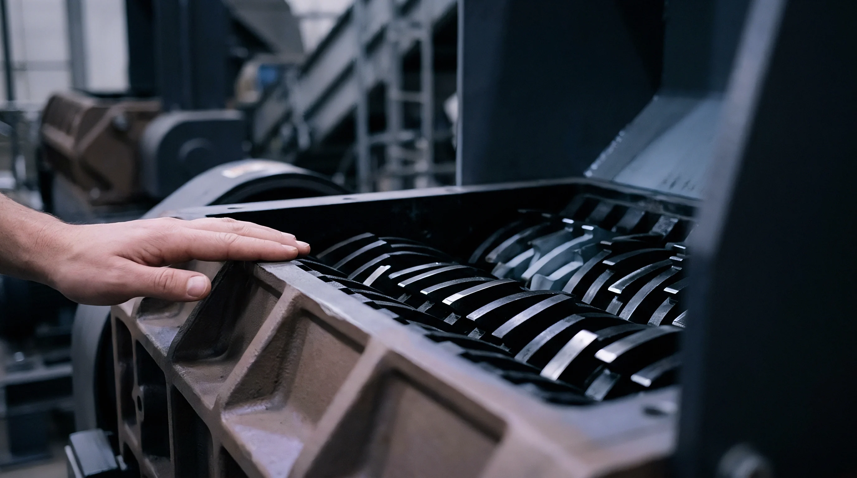
Viscoelastic Relaxation and Molecular Memory
Chain entanglements act as temporary physical junctions that store energy under deformation. Dynamic mechanical testing records this stored energy as the storage modulus, while dissipated energy appears as the loss modulus. Their ratio ~ the loss tangent ~ shifts sharply with temperature and shear frequency.
Short relaxation times allow chains to return to random orientations before exiting the channel. Longer relaxation times ~ common in high-molecular-weight fractions near their melting point ~ preserve aligned structures through the exit. These oriented chains store strain energy that releases outside the die, causing cross-sectional expansion that alters profile geometry:
- Melt Temperature Drop increases molecular relaxation time past die land residence time, locking in elastic strain.
- Normal Stress Amplification increases stored elastic energy during entry shearing.
- Die Exit Unconstraining releases normal stresses, driving anisotropic cross-sectional expansion.
- Asymmetric Thermal Shrinkage produces uneven cooling across the profile, locking in warping stresses.
Die design relies on land length to provide time for stress relaxation prior to exit. Extending the die land increases residence time so elastic stress can dissipate as heat within the channel. However, longer lands increase pressure drop and mechanical shear, which can elevate melt temperatures and introduce new thermal gradients.

How Does Thermal Hysteresis Alter Extrudate Dimensions?
Thermal history inside the barrel creates molecular entanglement networks that persist even after the melt reaches its nominal temperature. Melting polymer pellets into a uniform fluid requires breaking physical secondary bonds so chains can interdiffuse. Rapid heating cycles can leave non-uniform entanglement densities in the melt stream even when surface thermocouples indicate steady conditions.
Regions with residual crystalline structure or non-equilibrated entanglements exhibit altered relaxation profiles. Denser entanglement networks store more energy, increasing elastic recovery and swell. Resin passing through barrel zones with malfunctioning heater bands retains structural memory that distorts final dimensions, even if downstream mixing homogenizes surface temperatures.
Tracking swell variations requires continuous optical diameter measurements paired with high-frequency pressure sensors upstream of the die. Sudden shifts in swell ratio without a corresponding pressure change indicate thermal hysteresis or incoming lot variation. Static die tooling cannot adjust for these viscoelastic shifts, leading to higher scrap rates during scale-up.
What precise ratio of molecular weight distribution tailing to localized channel shear heating causes extrudate swell to shift from uniform swelling to irreversible melt fracture along profile edges?

Soak
Achieving thermal equilibrium inside a plasticizing barrel requires sufficient residence time for heat to conduct through the polymer mass. Steel barrels have high thermal inertia and respond slowly to controller adjustments. As screw flights convey, compress, and melt incoming pellets, heat enters through both wall conduction and internal friction.
Inadequate thermal soaking leaves unmelted gels, temperature fluctuations, and severe viscosity variations along the screw.
Residence time distribution measures how long different elements of polymer remain in the barrel. A broad distribution means some fluid exits quickly without absorbing enough heat, while other material stagnates and degrades. Consistent processing requires a narrow distribution where every element undergoes the same thermal and shear history before entering the mold or die.
Prolonged exposure to high temperatures degrades polymer chains. Chain scission reduces molecular weight and melt viscosity, whereas cross-linking increases viscosity and forms insoluble gels. Either mechanism alters flow behavior, throwing off machine settings and compromising part performance.
Operating near degradation limits leaves little margin for error in barrel energy balance and residence times.

Residence Time Distribution and Thermal Aging
Screw geometry dictates flow paths and establishes the residence time distribution. Barrier screws separate melt from solid pellets early, improving heat transfer and narrowing the residence distribution. Standard single-flight screws allow melt and solid bed to travel together, creating hot spots and broad residence distributions that cause output surging.
Stagnant areas around adapters, breaker plates, and nozzle tips present serious degradation risks. Trapped material absorbs heat continuously until it thermal-cracks or carbonizes. When these degraded particles break free into the main stream, they form black specks and structural defects in the finished part:
- Unmelted Particle Inclusion creates stress concentrations, reducing impact strength and causing surface blemishes.
- Molecular Chain Scission drops average molecular weight, lowering melt strength and triggering flash along parting lines.
- Thermal Cross-Linking generates high-viscosity gels that clog filter packs, mar surface finishes, and cause localized flow hesitation.
- Additive Volatilization releases gaseous byproducts that create surface splay, internal voids, and mold deposits.
Measuring residence time distribution involves introducing tracer dyes or color concentrates into the hopper and tracking their concentration at the nozzle over time. The resulting curve indicates mean residence time and mixing efficiency. A broad curve points to poor conveyance dynamics, signaling a need for screw modifications or adjusted temperature profiles.
Barrel Zone Energy Balance Dynamics
Barrel heating systems balance electrical heat input against mechanical shear generated by the screw. Modern controllers use PID loops to regulate heater band power based on thermocouple feedback. However, wall-embedded thermocouples measure metal temperature rather than melt temperature, introducing response lag and measurement error.
| Polymer Matrix | Processing Range (deg C) | Degradation Onset (deg C) | Max Residence Time at Peak Temp (min) | Primary Degradation Mechanism |
|---|---|---|---|---|
| Polyvinyl Chloride (Rigid PVC) | 170 – 195 | 200 | 5.0 | Dehydrochlorination / Cross-linking |
| Polymethyl Methacrylate (PMMA) | 220 – 260 | 275 | 12.0 | Unzipping Depolymerization |
| Acrylonitrile Butadiene Styrene | 230 – 270 | 280 | 8.0 | Rubber Phase Oxidation / Scission |
| Polyphenylene Sulfide (PPS) | 300 – 340 | 360 | 15.0 | Thermal Oxidation / Branching |
When high screw speeds generate excessive mechanical heat, zone controllers reduce electrical power to zero. If shear heating continues to exceed thermal loss, barrel temperatures drift upward in thermal runaway. Operators must balance screw speed, backpressure, and barrel cooling loops to stabilize energy input without overheating the melt.
Barrel heater zones cycle off while melt temperatures continue rising from mechanical shear energy alone.
Purchase specifications for high-capacity plasticizing units should mandate spatial melt temperature uniformity within plus or minus 1.5 degrees Celsius across full shot capacity during continuous runs.

Margin
The processing window maps combinations of melt temperature, mold temperature, and flow rate that yield acceptable parts. Resins with high thermal stability and low shear sensitivity offer wide windows that tolerate minor ambient fluctuations. High-performance engineering polymers have narrow windows, requiring tight control to prevent cosmetic flaws, structural failure, or mold damage.
Accelerating line speeds to boost throughput narrows these processing windows. Higher speeds increase shear rates and mechanical heating, closing the margin between thorough melting and thermal degradation. Pushing past thermal stability limits results in weight variation, dimensional drift, and scrap rates that offset any cycle-time savings.
Volumetric stability depends on maintaining consistent melt density throughout the molding cycle. Polymer density varies continuously with temperature and pressure according to PVT equations of state. Melt temperature drift alters density profiles, changing the mass injected into mold cavities under fixed volumetric stroke settings.
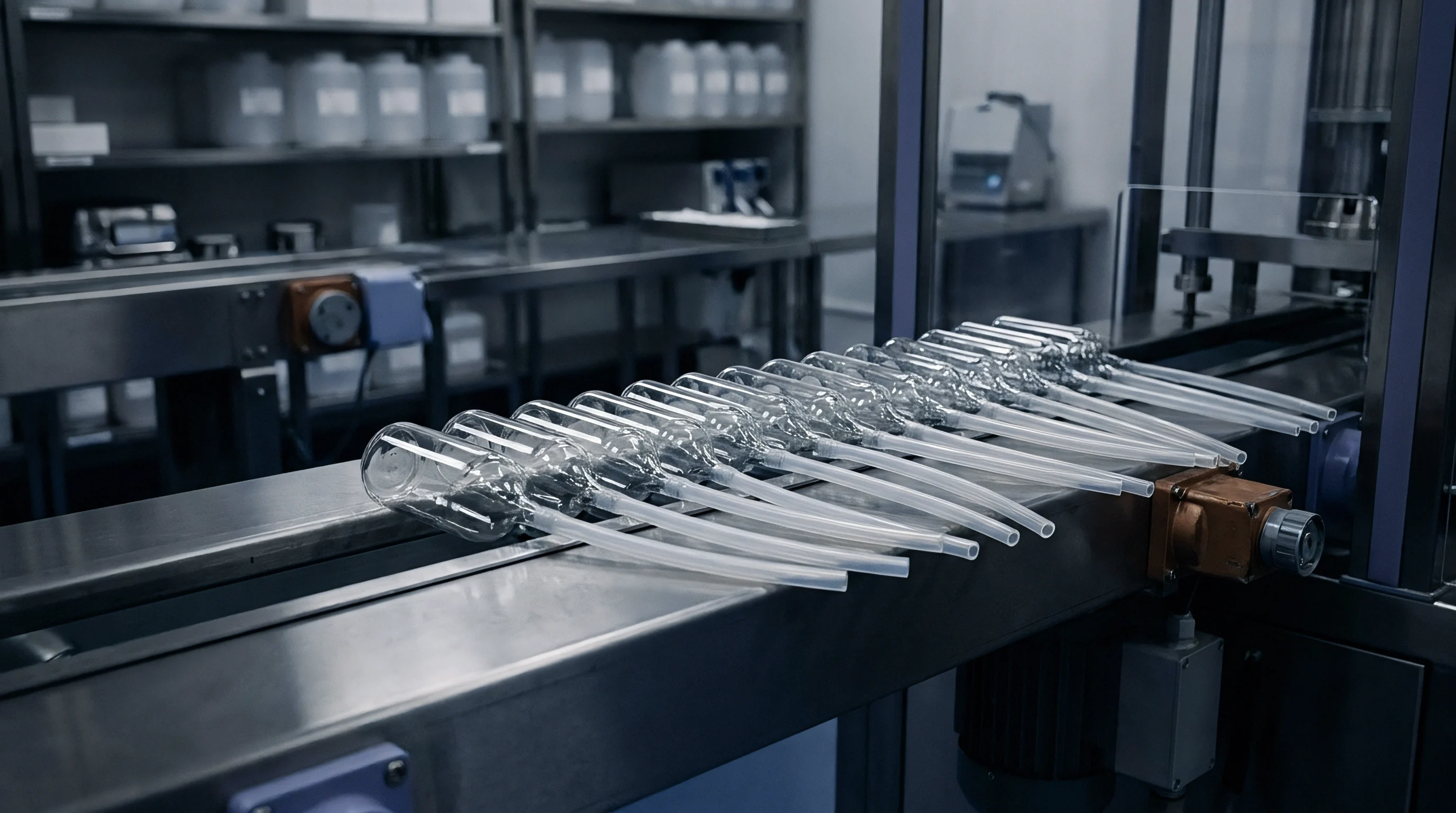
Process Window Narrowing under Scale Acceleration
High-speed processing amplifies minor variations into major defects. A temperature shift of two degrees Celsius ~ harmless at lower speeds ~ can cause flash or sink marks at maximum output. Increased shear rates elevate boundary heating, altering fill balance in multi-cavity molds and producing uneven packing.
Mapping stable operating windows requires structured design-of-experiments testing. Evaluating systematic combinations of melt temperature, injection speed, and hold pressure establishes boundary limits for short shots, warpage, and flash. Centering production settings within that window builds robustness against ambient temperature shifts, cooling water drift, and resin batch variations.
Maintaining stability across shifts requires strict machine setup protocols. Thermal equilibrium must be verified before checking part dimensions or approving production runs:
- Preheat barrel zones to target temperatures and hold for forty-five minutes to reach full thermal equilibrium in the metal.
- Purge high-shear barrel zones with high-viscosity purge resin to clear out stagnant material and degraded polymer.
- Engage screw rotation at production speed, monitoring motor load to spot any un-melted resin.
- Measure stock melt temperature directly using a handheld immersion probe in purged resin mass, comparing against barrel wall display readings.
- Cycle the injection unit through twenty dummy shots, purging mass until thermal equilibrium stabilizes under continuous load.
- Start automated mold filling, tracking peak cavity pressure and part weight stability over thirty consecutive cycles.
Skipping this thermal stabilization routine introduces inconsistent heat histories into initial parts, causing latent warpage that manifests days later in storage.

Volumetric Delivery Stability and Dimension Tolls
Consistent dimensions depend on delivering identical polymer mass on every cycle. Because metering units measure stroke volume rather than shot mass, density variations alter the mass delivered per shot. Thermal drift shifts density, driving part weight fluctuations and dimensional variation across production runs.
Compressibility during hold phases compounds volume errors. Polymer melts compress by three to eight percent under high holding pressure. Hotter melt compresses more, requiring larger holding stroke adjustments to keep density steady.
When melt temperature drifts, fixed hold pressures deliver inconsistent mass, destabilizing part dimensions.
Shrinkage correlates directly with thermal history during cooling. Semi-crystalline polymers such as polypropylene and nylon shrink by up to two percent during crystallization. Higher melt temperatures delay crystallization, giving molecules more time to relax and increasing total part shrinkage.
Holding tight tolerances requires keeping melt temperatures within narrow bounds across shifts.
Thermal equilibrium at the barrel guarantees consistent volumetric delivery only if mold cooling flow remains fully turbulent.


Control
Controlling non-isothermal polymer processes demands accurate real-time measurement of fluid temperatures. Standard thermocouples mounted flush with barrel walls measure steel temperature rather than melt temperature. Because polymer melt is a poor thermal conductor, wall sensor readings lag actual core temperatures by tens of seconds, leaving basic feedback loops unable to capture fast thermal transients during high-speed cycles.
Advanced sensors provide clearer thermal visibility inside flow channels. Immersion probes extending into the stream measure core temperatures, but disrupt flow lines and generate local shear heating around the tip. Flush-mounted infrared sensors read radiant energy through quartz windows, offering fast response times without disturbing flow.
However, infrared sensors capture surface temperatures near the window, relying on calibration algorithms to infer internal core profiles.
Closed-loop controllers integrate real-time temperature, pressure, and flow readings to adjust machine settings dynamically. Melt temperature feedback alters barrel heater power and backpressure to hold enthalpy steady at the nozzle. Advanced systems use model predictive control algorithms, factoring in non-linear viscosity, shear heating, and thermal lag to stabilize conditions across varying line speeds.
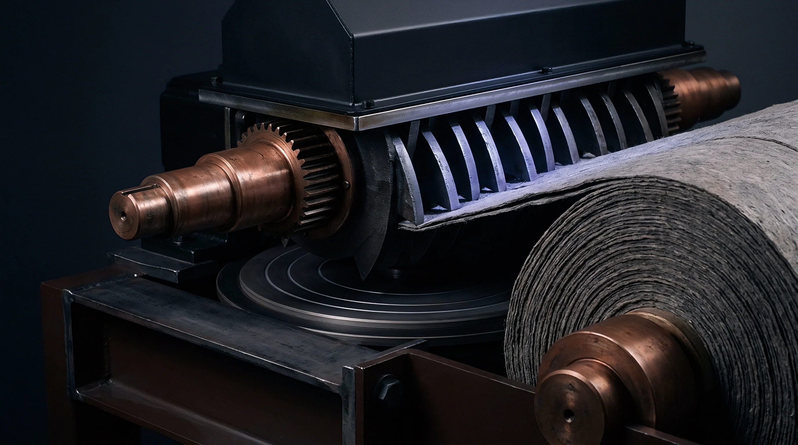
Sensor Dynamics and Temperature Measurement Errors
Selecting sensor hardware involves trade-offs among speed, accuracy, and durability. Heavy steel-sheathed thermocouples withstand high barrel pressures but carry time constants exceeding fifteen seconds. Fast-response exposed-junction sensors wear down rapidly in abrasive glass-filled resin streams, leading to calibration drift and failure.
Ultrasonic systems determine melt temperatures by tracking acoustic velocity across channel cross-sections. The speed of sound in polymer melt depends directly on density and bulk modulus, which track closely with temperature. Ultrasonic probes yield real-time bulk temperature measurements across the full stream without obstructing flow, providing reliable control signals for high-precision extrusion:
| Sensor Technology | Response Time (ms) | Measurement Volume | Flow Obstruction | Calibration Drift Susceptibility |
|---|---|---|---|---|
| Standard Flush Thermocouple | 5,000 – 15,000 | Barrel Wall Interface | None | Low |
| Immersion Probe Thermocouple | 500 – 2,000 | Localized Stream Depth | High | Medium |
| Fiber-Optic Infrared Sensor | 1 – 10 | Surface Fluid Layer | None | High (Window Clouding) |
| Cross-Channel Ultrasonic Probe | 10 – 50 | Bulk Cross-Section Average | None | Low |
Immersion probes must be positioned carefully to avoid shear heating errors. Sensors placed in high-velocity channels generate local viscous heating, reading several degrees higher than true bulk melt. Positioning probes in lower-velocity zones downstream of static mixers minimizes friction errors, yielding representative thermal readings for closed-loop feedback.

Closed-Loop Rheological Balancing Protocols
Feed-forward controls use real-time die channel pressure measurements to detect viscosity shifts before material exits the tool. If resin viscosity climbs, pressure drop across the die increases instantly at constant gear pump speed. Control algorithms detect this rise and adjust barrel setpoints or screw speeds to return viscosity to the target range.
Dynamic thermal management divides the barrel into multiple control zones fitted with heating and cooling elements. When mechanical shearing drives temperatures above setpoint, zone controllers activate cooling jackets to extract energy through the barrel walls. This dual heat-cool regulation stabilizes melt temperature profiles, preventing thermal runaway during high-speed runs.
Integrating online capillary rheometers into control loops allows continuous viscosity monitoring during production. A small side stream of melt flows through a calibrated capillary die, where pressure transducers compute real-time shear viscosity at controlled rates. Viscosity shifts trigger automated adjustments to barrel temperature profiles or liquid additive pumps, maintaining consistent properties despite lot variation.
Automated rheological control eliminates the need for periodic offline melt flow testing, preventing out-of-spec production runs. Combining fast sensors, predictive software, and active cooling stabilizes the thermal-rheological feedback loop to protect product quality during high-volume runs.