In-Mold Sensor Installation for Real-Time Polymer Gelation Inspection
In-mold dielectric and ultrasonic sensors eliminate conservative press hold timers by triggering part ejection precisely at polymer vitrification.


Port
Fitting a cavity sensor into an active production mold requires holding tolerances within five micrometers of the tool face. Whether running thermoset resin transfer molding, reaction injection molding, or high-pressure sheet molding compound, the seam between the sensor housing and the tool steel directly affects signal quality and part appearance. Even minor misalignment creates witness marks or flash.
Sensors used for real-time gelation tracking monitor dielectric properties, ultrasonic sound speed, micro-cavity pressure drops, or localized heat flux. In every case, the transducer face must maintain direct physical contact with the resin as it moves from a liquid melt through the gel point and into solid vitrification. Housing these instruments in hardened tool steel means cutting a precise pocket, designing a seal that can withstand mold pressures exceeding fifteen megapascals, and isolating the sensor body so tool heating bands do not distort raw signal data.

Tool Steel Preparation and Surface Flush Tolerances
Cutting the mounting pocket into P20, H13, or stainless steel plates requires CNC sinker electrical discharge machining to hold tight wall clearances. If the sensor head stands proud of the cavity, it produces a stress concentration in the molded part; if it sits too deep, resin pools over the face and shears off during ejection. The target flushness tolerance is positive zero micrometers to negative five micrometers against the adjacent cavity surface.
Axial depth is set by a precision shoulder stop on the sensor sleeve that bottoms against a ground landing on the back of the cavity insert. Ground 316 stainless steel shims allow height adjustment in two-micrometer steps. Checking cavity wall deflection under injection pressure separates tool plate flexing from sensor drift, since thermal gradients across the tool can quickly ruin measurement accuracy.
Transducer face roughness needs to match the cavity finish. Micro-dielectric sensors on ceramic or polyimide carriers use delicate interdigitated electrodes that cannot be post-polished once assembled. These ceramic units are ground coplanar at the factory, with the substrate potted flat inside a titanium or stainless steel collar using high-temperature epoxy.
By contrast, ultrasonic transducers use solid metal delay lines that can be lightly lapped alongside the tool steel during regular mold refurbishing.
In-mold dielectric sensors installed with a face recess exceeding seven micrometers capture stagnant resin pockets that gel prematurely compared to the bulk cavity melt.
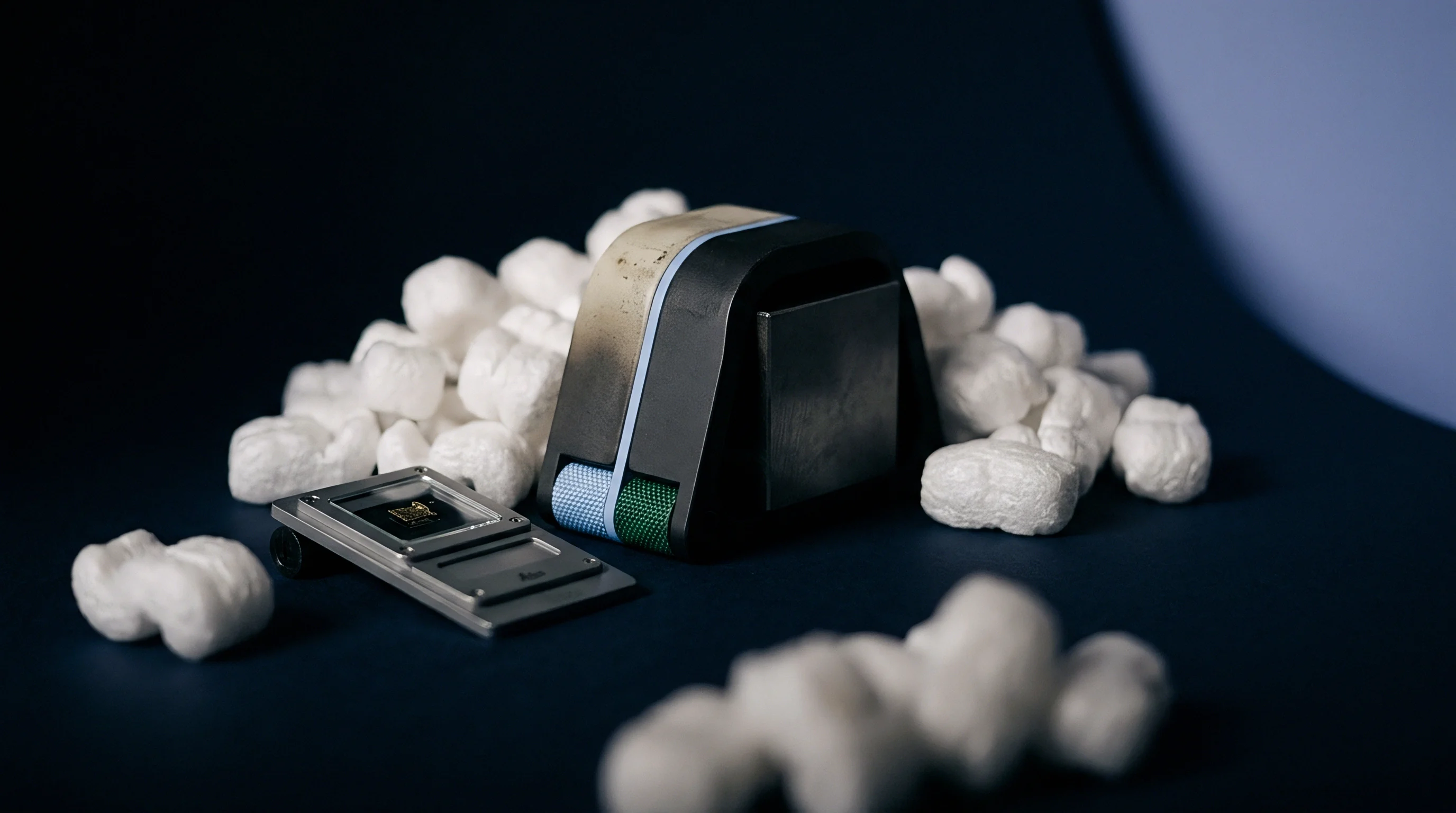
Thermal isolation is essential for preventing signal drift. Direct contact between the metal sensor body and mold heating channels introduces thermal noise that skews capacitance and loss-factor data. Machinists must leave room in the pocket for a thin-walled polyether ether ketone or ceramic insulator sleeve, which decouples the transducer from the hot mold plates while handling heavy compressive clamping loads.
Thermal Isolators and High-Pressure Cable Pass-Throughs
Reliable gelation detection requires thermal stability across the sensor face. As thermoset resins crosslink, the exothermic reaction generates a rapid local temperature spike. If the sensor housing draws heat away like a heat sink, the thin resin layer at the transducer face cools down, slowing local crosslinking and showing a false delay in gelation that does not match the bulk part.
Maintaining near-adiabatic conditions requires low-conductivity ceramic sleeves made of zirconium oxide. Zirconia delivers compressive strength above two gigapascals with thermal conductivity below three watts per meter-kelvin, well under the twenty-five watts per meter-kelvin typical of standard tool steel. This barrier insulates the sensing element so the polymer film against the face tracks the actual thermal path of the bulk melt.
Getting signal leads out of the mold demands careful routing to avoid damage during press movement. Low-amplitude ultrasonic and micro-dielectric leads need dedicated channels milled into the back of support plates, and they should never cross parting lines without protective steel conduit. Where leads pass through moving ejector plates, flexible stainless steel armor sleeves protect internal conductors through the full mechanical stroke.
Sealing Ring Geometries and O-Ring Thermal Limits
Keeping resin out of back-plate wiring channels requires elastomer seals that can endure repeated twenty-megapascal pressure spikes. Under that load, liquid resin will work its way into sub-micron gaps between the sensor body and pocket wall. If resin reaches the space behind the sensor, it cures in place, locking the assembly into the tool and ruining the wiring harness.
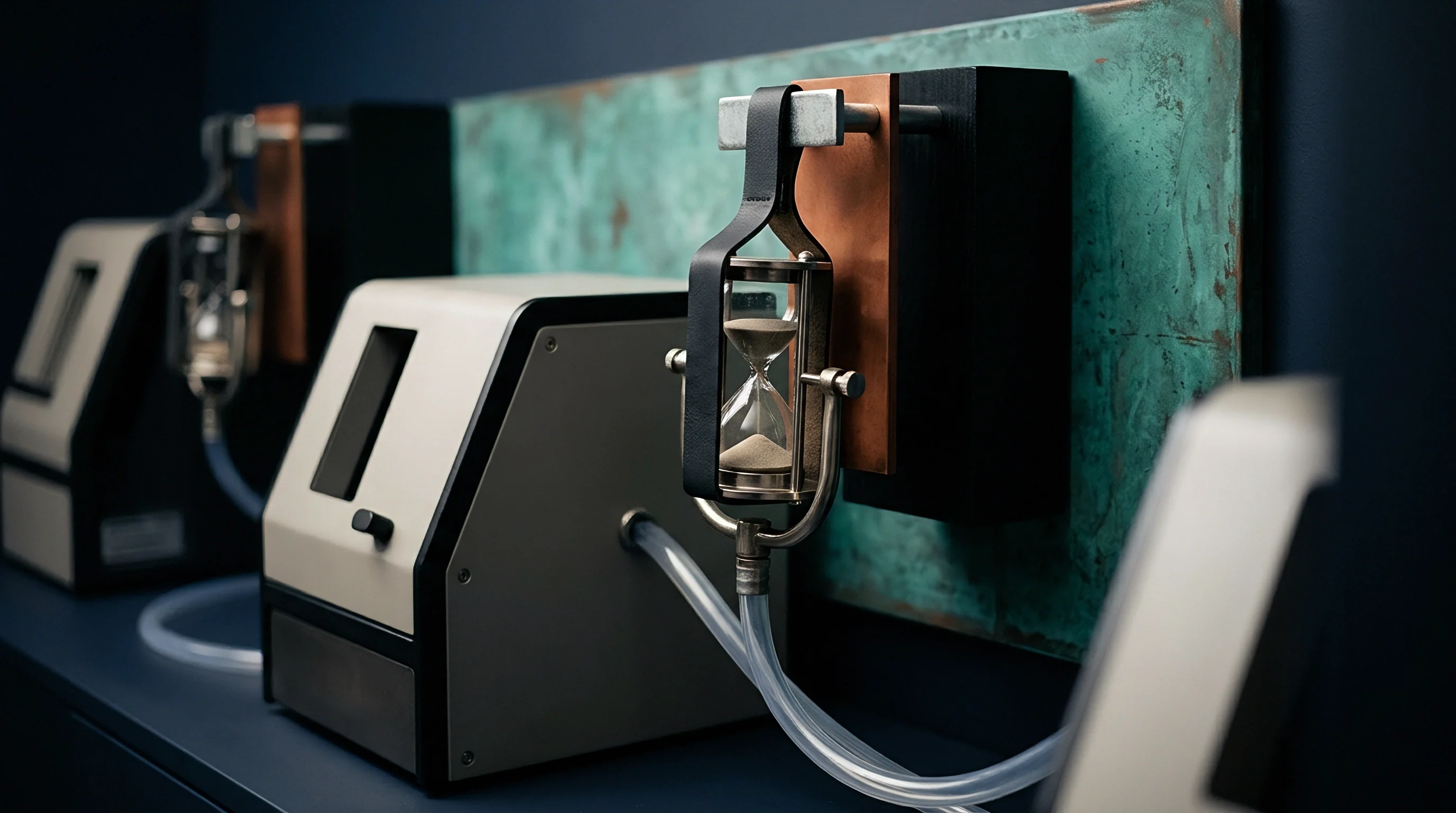
Primary sealing is handled by a metal crush ring or a precision-machined elastomeric O-ring groove positioned behind the sensor shoulder. Perfluoroelastomer seals handle continuous operating temperatures of three hundred degrees Celsius while resisting chemical attack from anhydrides, amines, and styrene monomers. Groove dimensions must maintain a strict depth-to-width ratio to provide fifteen to twenty percent radial compression without overfilling the gland during thermal expansion.
When a seal fails, resin monomer leaks into the rear pocket clearance and polymerizes around the coaxial connector. Extracting the damaged hardware requires drilling through the back plate from behind, destroying a twelve-thousand-dollar micro-dielectric transducer assembly and idling the line for two operational shifts.
| Parameter | Dielectric Sensor (DEA) | Ultrasonic Transducer (UT) | Combined Pressure-Temperature |
|---|---|---|---|
| Flushness Tolerance | +0 / -5 µm | +0 / -10 µm | +0 / -5 µm |
| Max Mold Pressure | 200 bar (Polyimide) / 1500 bar (Ceramic) | 2000 bar | 2500 bar |
| Operating Temp Limit | 230 °C (Standard) / 380 °C (High-Temp) | 350 °C | 400 °C |
| Pocket Surface Roughness | Ra 0.2 µm | Ra 0.4 µm | Ra 0.2 µm |
| Isolation Material | Zirconia / PEEK Sleeve | Polyimide Spacer | Hardened Tool Steel Collar |
Pocket preparation requires careful sequencing. The steps below outline the standard workflow for machining the steel, cutting conduit paths, and verifying sensor fit before production sign-off.
- Tool Pocket EDM Milling establishes receiving geometry in hardened tool steel plates with five-micrometer wall concentricity relative to cavity datum features.
- Wiring Conduit Routing cuts protective back-plate channels to guide armored coaxial cables clear of ejector pins and clamping platens.
- Isolation Sleeve Press-Fitting seats high-strength zirconia insulator bushings into the steel pocket housing under controlled hydraulic force.
- Depth Profilometry Mapping measures micro-step height from tool cavity face to internal mounting shoulder using optical white-light interferometry.
- Shimming and Seal Seating selects ground stainless steel spacers and places perfluoroelastomer O-rings to set final flushness depth.
- Torque-Controlled Installation tightens rear retention bolts to specified values, preventing sensor face tilt under high thermal cycles.
- Parting Line Signal Clearance Audit verifies continuity and electrical isolation against tool ground while the press cycles under cold clamping force.
Retrofitting active molds is significantly more expensive than designing pockets into new tooling from the start. On an eight-cavity transfer mold, a retrofit required wire EDM cutting, plate rework, custom wire harnessing, and rebalancing the heat zones around each pocket. The structural rework ran thirty-eight thousand dollars in direct labor and cost ten days of lost press time, showing how quickly post-build modifications outpace hardware purchase costs.


Kinetics
Tracking the transformation of liquid thermoset resins into solid crosslinked networks involves monitoring physical properties across the cavity during cure. As reaction chemistry progresses, chain extension and branching drive a rapid climb in molecular weight. At the gel point, the continuous network turns the material from a viscous liquid into an insoluble viscoelastic gel.
While initial mold heating drops resin viscosity, gelation halts flow entirely.
Cavity sensors capture this progression by measuring changes in ion mobility or acoustic impedance. Dielectric units apply high-frequency electrical fields to interact with polar groups and mobile ions in the resin. Ultrasonic transducers send high-frequency sound waves through the cavity, using shifts in acoustic velocity and signal damping to follow the development of crosslink density.

Dielectric Analysis and Ultrasonic Phase Tracking
Ion viscosity curves reflect the mobility of reactive polymer chains. Dielectric monitoring measures two responses under an alternating electric field: permittivity, which tracks dipole alignment, and loss factor, which measures energy dissipated through ion movement and dipole rotation. Early in the cycle, low resin viscosity allows free ions to migrate easily, producing high loss factors and low ion viscosity values.
As the polymer network forms, bulk viscosity climbs by orders of magnitude and impedes ion travel. The measured ion viscosity ~ the reciprocal of ionic conductivity ~ rises alongside physical viscosity until the resin gels. Past gelation, restricted movement shifts the dominant dielectric response from ionic drift to dipole relaxation, while mold pressure compresses the raw baseline signal.
Ultrasonic phase tracking provides a complementary acoustic readout. The speed of a longitudinal ultrasonic wave depends on the storage modulus and bulk compressibility of the curing resin. Liquid resins cannot support shear waves, and longitudinal velocities remain low; once crosslinking establishes a gel network, the dynamic shear modulus climbs steeply, driving a rapid rise in sound velocity.

Does Dielectric Dissipation Factor Track Gel Point Accurately?
Taking the time derivative of log ion viscosity pinpoints the gel transition. In epoxies, polyesters, and polyurethanes, the gel point aligns with the inflection point where the rate of ion viscosity change reaches its maximum. Watching the derivative curve is far more reliable than setting an absolute ion viscosity threshold, which shifts with raw material lot variations and moisture levels.
Using the logarithmic derivative separates cure kinetics from initial batch conductivity. On a derivative plot, this transition appears as a sharp peak. Parallel-plate oscillatory shear measurements confirm that this dielectric peak matches the crossover of storage modulus (G’) and loss modulus (G”) at standard test frequencies.
Changing electrode spacing on interdigitated sensors alters raw signal amplitude without shifting the position of the derivative peak.
Fast-reacting formulations under non-isothermal conditions complicate this relationship. When rapid exothermic heating thins the resin while simultaneously accelerating crosslinking, the dissipation factor curve can develop multiple local peaks if the temperature rise outpaces reaction kinetics. In those situations, active temperature compensation using an integrated surface thermocouple is required.
Standard ISO 20368 dictates that dielectric cure monitoring must include simultaneous temperature acquisition at the sensor face to separate thermal conductivity changes from chemical crosslinking transitions.

Distinguishing Gelation from Vitrification in Thermoset Resins
Under an isothermal cure cycle, crosslinking involves two distinct transitions. Gelation marks the liquid-to-rubber change where macroscopic flow stops while reaction chemistry continues at full pace. Vitrification is the shift from a rubbery or gelled network into a rigid glassy solid, occurring when the network’s rising glass transition temperature (Tg) reaches the tool temperature.
On a dielectric readout, vitrification appears as the ion viscosity curve levels off into an asymptotic plateau. At this stage, restricted molecular movement traps unreacted functional groups and slows the reaction rate near zero. The loss factor drops to background noise as dipole movement freezes, while ultrasonic velocity levels off at maximum speed.
Ultrasonic attenuation curves show a distinct peak right at the vitrification boundary. As the polymer enters the glass transition region, structural relaxation times align with the acoustic excitation frequency, absorbing maximum energy from the sound wave. Reading the velocity plateau alongside this attenuation peak gives operators positive confirmation that the part has achieved enough hot rigidity for clean demolding.
| Inspection Modality | Primary Kinetic Metric | Gel Point Indicator | Vitrification Indicator | Sensitivity to Fillers |
|---|---|---|---|---|
| Dielectric (DEA) | Ion Viscosity / Loss Factor | Log Derivative Inflection Peak | Log Curve Flat Asymptote | Low (Ignores Inert Carbon/Glass) |
| Ultrasonic (UT) | Sound Velocity & Attenuation | Velocity Slope Increase Start | Attenuation Dissipation Peak | High (Scatters off Fibers/Pores) |
| Cavity Pressure | Volumetric Contraction Rate | Post-Fill Slope Break | Pressure Drop Plateau | Moderate (Apparent Density Shifts) |
| Heat Flux | Exotherm Heat Release Rate | Heat Rate Peak Position | Zero Heat Generation Return | Moderate (Thermal Mass Changes) |
Process drift outside validated operating windows creates signal artifacts that mislead process tracking. Common failure modes encountered during production runs include:
- Interfacial Micro-Gapping occurs when polymer shrinkage creates a physical air gap at the sensor face, causing sudden artificial drops in loss factor and loss of acoustic coupling.
- Thermal Gradient Shift occurs when mold heating bands cycle unevenly, introducing artificial slope changes into ion viscosity curves that mimic gelation inflection points.
- Electrode Polarization occurs in high-conductivity resins at low excitation frequencies, building double-layer charge at sensor contacts that masks early-stage cure kinetics.
- Particulate Shielding occurs when dense glass mat reinforcements bridge directly over interdigitated sensor tracks, shielding the underlying resin from applied electric fields.
- Cable Noise Coupling occurs when unshielded signal leads run parallel to high-voltage press power lines, swamping micro-ampere sensor signals with 60 Hz electromagnetic hum.
Published cure rates reflect static laboratory rheology rather than pressurized flow in production tooling, meaning lot-to-lot gelation variances in an isothermal tool can exceed twenty-five percent. Relying on nominal cure data leaves molders carrying the scrap costs whenever an off-spec lot fails to cure within standard timer limits.


Signal
Electrical noise from mold heaters can easily swamp micro-volt signals from cavity transducers. In-mold inspection requires detecting tiny phase shifts, fractional picofarad capacitance changes, or nanosecond ultrasonic transit variations inside a harsh press environment. With multi-kilowatt heater bands, servo motors, and induction units running nearby, unshielded instrument lines quickly pick up severe interference.
Data acquisition hardware needs signal conditioning mounted directly on the mold platen. Placing conditioning near the tool turns sensitive, high-impedance outputs into noise-immune digital data or low-impedance differential signals before cables run through moving tracks to the main press controller. Proper isolation protocols also require separating sensor ground paths entirely from heavy machine earth.
Data Acquisition Architecture and Electromagnetic Shielding
Lines carrying micro-ampere ionic currents need differential preamplifiers right at the outer mold frame. Micro-dielectric systems typically operate from zero point one hertz to one hundred kilohertz with current levels in the nano-amp range. Running these low-level analog signals across three meters of flexible conduit to an external cabinet introduces excessive noise from adjacent drive motors.
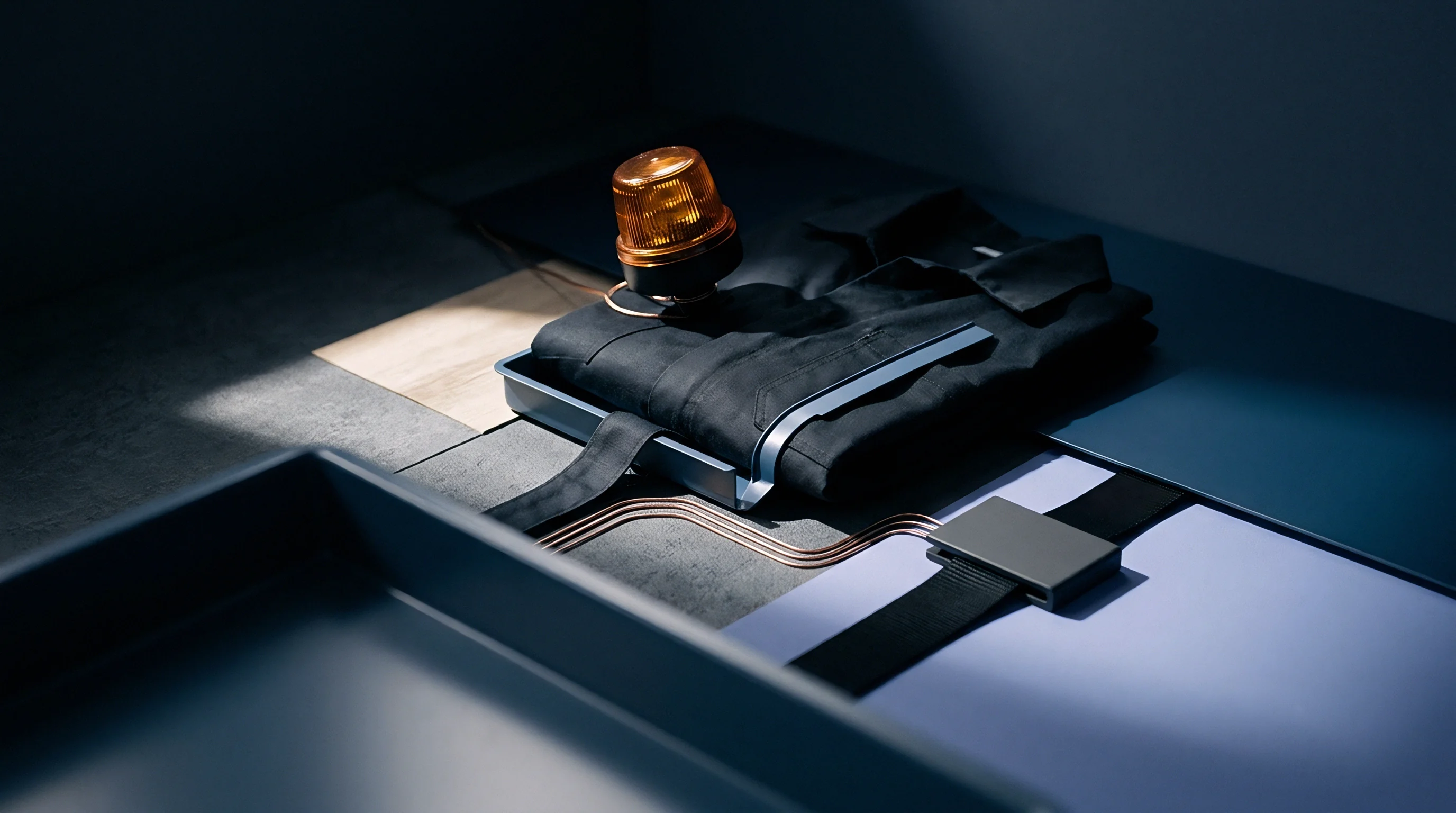
Mounting a signal junction box on the stationary platen keeps unshielded analog lead lengths under thirty centimeters. The standard configuration uses triple-shielded coaxial or twisted-pair wiring with braided copper outer screens and aluminized Mylar inner foil. The outer shield ties to instrument ground at the acquisition cabinet while floating at the tool box, preventing destructive ground loop paths.
Ultrasonic systems rely on high-voltage pulser-receivers generating excitation pulses up to three hundred volts, followed by fast switching to capture millivolt-level echoes. High-speed acquisition boards must sample incoming acoustic waveforms at a minimum of one hundred megahertz with twelve-bit vertical resolution to resolve time-of-flight shifts as small as two nanoseconds during crosslinking, while data logging runs uninterrupted.

Closed-Loop Cure Control and Demold Triggering
Triggering mold opening on real-time cure state eliminates the padding built into fixed timers. Traditional thermoset molding relies on conservative cure cycles sized for worst-case material batches and thermal dips, adding fifteen to thirty percent to overall cycle time simply to avoid ejecting under-cured parts.
Closed-loop control routes in-mold kinetic data directly to the press logic to optimize cycle economics. The acquisition unit calculates the logarithmic derivative of ion viscosity or tracks ultrasonic velocity against preset setpoints in real time.
Once the system confirms the resin has vitrified and reached its target glass transition temperature, it sends an opening command to the press PLC. The mold opens immediately for ejection without waiting out an arbitrary timer. If a slow-reacting batch enters the cavity, the system holds the press closed until the part develops adequate green strength, preventing structural distortion or delamination upon demold.
Integrating real-time dielectric vitrification tracking into high-volume composite press controls reduces average cycle times by eighteen percent while eliminating sub-threshold cure scrap entirely.

Baseline Alignment with Off-Line Rheology Records
Dynamic mechanical analysis characterizes resin cure under bench conditions that differ substantially from an active mold. Standard laboratory rheology uses parallel plates in small-amplitude oscillatory shear at one hertz under controlled, linear heating. Inside the cavity, by contrast, the resin experiences non-isothermal temperature spikes, aggressive flow shear during injection, and hydrostatic pressures up to twenty megapascal.
Setting in-mold voltage thresholds against lab curves requires correlating dielectric loss factor profiles with storage modulus (G’) development. Resin samples should be tested simultaneously in a pressurized dielectric cell and a dynamic mechanical analyzer running matching temperature programs. The G’/G” crossover at one hertz provides the baseline reference used to set real-time demold triggers.
Braided copper shielding on all low-current coaxial lines blocks inverter noise. Because thermal expansion differences between the steel pocket and the sensor’s ceramic body cause baseline shifts between a cold start and the one hundred eighty degrees Celsius operating temperature, software calibration routines must re-zero open-cavity baselines before resin enters on each cycle.
| Control Variable | Dielectric Interface | Ultrasonic Interface | Acceptable Noise Threshold |
|---|---|---|---|
| Excitation Signal | 1 V to 10 V RMS AC (0.1 Hz – 100 kHz) | 100 V to 300 V Pulse (1 MHz – 10 MHz) | < 0.5% Total Harmonic Distortion |
| Sampling Rate | 10 Hz (Kinetics) / 100 Hz (Injection) | 100 MHz Digitization | No Missed Packet Frames |
| Amplification Gain | 0 dB to 60 dB Programmable | 20 dB to 80 dB Low-Noise Amplifier | Signal-to-Noise Ratio > 40 dB |
| Demold Trigger Gate | d(log IV)/dt < 0.01 for 5 seconds | Sound Velocity > 2400 m/s Plateau | Zero False Triggers per 10,000 Cycles |
Hardware installations must meet strict validation criteria before handing over control to automated demold routines. The checklist below covers the requirements for sign-off.
- Transducer Baseline Calibration verifies open-cavity signal stability across three complete mold heating and cooling thermal cycles.
- Electromagnetic Isolation Audit verifies signal noise remains below ten millivolts while all press hydraulic pumps, electric drives, and heater zones operate at full power.
- Rheological Correlation Profile matches dielectric loss factor inflection points against laboratory shear modulus gelation records for the specific resin formulation batch.
- Thermal Compensation Mapping confirms real-time surface thermocouple readings correctly offset temperature-induced ionic mobility variations.
- PLC Communication Fail-Safe establishes automated safety drop-outs that revert press operation to fixed conservative timers if sensor signal continuity breaks during a cycle.
Equipment supply contracts should state clear performance standards for noise immunity and software integration. Purchase terms need to require unencrypted access to raw high-frequency data streams and derivative algorithms, allowing plant process engineers to adjust closed-loop demold rules without vendor intervention or unlock fees.


Bore
Gun-drilling long wiring passages through mold plates involves tricky mechanical routing. Leads must navigate thick backing plates without intersecting cooling passages, ejector pin bores, or structural support pillars. Hitting a water line ruins the plate and floods high-voltage sensor junction boxes, while poor placement weakens the overall mold structure.
Operating in-mold instrumentation across multi-cavity tooling requires consistent maintenance routines. Sensor faces experience steady wear from abrasive glass-filled resins, chemical staining, and oxidation over tens of thousands of press cycles. Toolroom staff need clear protocols for cleaning, checking flushness, and swapping damaged sensor cores without damaging hardened cavity inserts.

Tool Maintenance and Ceramic Transducer Wear Mechanics
Abrasive glass-reinforced resins wear down sensor faces over extended production runs. As filled thermosets wash over the cavity surface at high velocity, hard glass fibers, mineral fillers, or metallic flakes scour the steel and erode thin electrode tracks. Micro-dielectric sensors using thin-film gold or platinum on ceramic will degrade rapidly if placed directly in line with gate impingement.
Best practice keeps delicate micro-dielectric sensors in lower-velocity cavity areas away from the gate, where melt flow stabilizes into laminar patterns. Ceramic substrates resist abrasion better than polyimide films, though ceramic edges can chip if tool plate deflection under clamp tonnage introduces localized bending stresses.
Ultrasonic transducers with solid steel or titanium delay lines hold up much better against abrasion. During routine tool maintenance, toolmakers can lap scratched delay line faces using fine diamond compound. Micro-dielectric sensors cannot be resurfaced; once the electrode tracks wear through, the entire core module must be replaced.

Economics of Multi-Cavity In-Mold Sensor Retrofits
Justifying retrofit projects financially comes down to trimming cycle times and cutting scrap from under-cured parts. High-cavitation tooling for automotive or electronic parts involves complicated cost calculations; instrumenting every pocket on a sixty-four-cavity mold means massive hardware expense and sixty-four separate harness connections that can fail.
A practical alternative is placing sensors in representative cavities rather than instrumenting the whole tool. Instrumenting the thermally coldest cavity, the one furthest from the manifold, and a cavity near the main runner gate provides effective visibility across the operational window. When the coldest and most remote cavity reaches vitrification, the rest of the mold has already cleared cure requirements.
Maintenance records show clear sensor wear patterns over time. Capital budgets should include ongoing maintenance items, such as swapping sensor heads around fifty thousand cycles and replacing harness seals during annual teardowns. Neglecting maintenance inevitably leads to failures during production runs, forcing operators back to long, conservative timer cycles.
Regular maintenance ensures dependable sensor operation over the life of the tool. The procedure below covers cleaning, face inspection, depth checks, and recalibration during scheduled service intervals.
- Demount sensor retention assemblies from the rear of the tool plate and extract internal wiring harness plugs.
- Clean accumulated resin residues from the sensor face using brass scrapers and chemical solvents specified for the target resin system.
- Inspect interdigitated electrode tracks or metal face coatings under ten-times optical magnification for physical scoring, cracking, or electrode peeling.
- Check perfluoroelastomer sealing ring condition, replacing any seal showing permanent compression set, hardening, or chemical degradation.
- Measure sensor face flushness against surrounding cavity steel using a digital depth micrometer at four quad points around the housing perimeter.
- Re-shim rear shoulder supports to correct flushness drift caused by mechanical plate wear or thermal deformation over prior production runs.
- Reinstall sensor housing, torque rear retention bolts to specified limits, and conduct electrical isolation checks against tool ground prior to remounting tool into press.
Placing sensors in low-velocity recirculation zones shields delicate micro-dielectric faces from abrasive wear, though positioning always involves balancing signal fidelity against sensor life. Routine bench inspections catch face wear before dropped signals disrupt active molding schedules.
Keeping mounting pockets and seals in good order allows in-mold sensors to deliver reliable cure tracking across millions of parts without risking tool steel damage. Supported by regular flushness checks and sound closed-loop demold logic, cavity sensors provide consistent cycle time reductions and scrap savings.