Modeling Dynamic Conveyor Buffer Sizes before Capital Expenditure Commitments
Dynamic conveyor buffer sizing uses empirical breakdown distributions in discrete event models to establish capital allocation bounds before hardware purchase.


Swell
An automated filling line running at six hundred units per minute goes down for forty-two seconds when a downstream cap chute misfeeds. Upstream machines keep discharging onto an unbuffered track. Within twelve seconds, thirty-six containers slam into the index wheel, backpressure sensors trip, and an emergency stop cascades all the way to the washer.
Production stops across the plant. The line loses two thousand four hundred units against rated capacity that hour, even though total station downtime was under ninety seconds, as queues rapidly back up.
Static line balancing calculates hourly output by multiplying nameplate speeds by nominal availability, assuming steady container flow through each conveyor section. Continuous production routinely breaks that assumption. Random minor stops, operator response lags, and speed differences between operations generate local accumulation surges.
When the conveyor between machines cannot hold arriving product during downstream interruptions, upstream stations have to shut down. This coupling pulls the entire line down to the efficiency of its worst-performing link.
Sizing the necessary accumulation volume requires integrating mass balance differential equations across transport zones. If containers enter a conveyor section at rate Rin(t) and exit at rate Rout(t), the work-in-progress stored on that track at time T is the integral of their rate differential over the duration of the downstream stoppage, absorbing the variability of the flow.

Physics of Transient Conveyor Queuing
Containers moving on powered transport shift rapidly between steady flow, deceleration, mass accumulation, and full pack. In free flow, transport velocity matches chain speed and spacing is uniform. A downstream stop sends a deceleration wave back up the line.
The lead container stops against a gate or a halted container, and the following units close the pitch gap behind it. Spacing collapses as kinetic energy turns into sliding friction between the moving chain and container bases.
Friction conveyors push continuously against stopped product during accumulation. Aggregate backpressure scales directly with queue length, container mass, and the chain surface friction coefficient. Linear capacity is simply track length divided by container dimension along the motion axis.
Multi-lane mass flow tracks expand capacity by letting containers displace laterally. Container shape governs pack density; cylindrical cans or bottles settle into hexagonal close-packed arrays with maximum volumetric utilization approaching zero point nine zero six.
Buffers must hold sufficient volumetric capacity to absorb total material discharge from upstream machinery during maximum expected downstream recovery durations.
Because line balance is dynamic, downstream machines must accelerate above upstream discharge rates once a fault clears to drain accumulated stock. If downstream equipment only restarts at nominal upstream speed, the buffer never empties. The queue stays full, leaving zero surge capacity for the next micro-stoppage.
Emptying a loaded accumulation zone typically demands downstream pull ratios between one point fifteen and one point thirty relative to upstream baseline output.

Static Capacity Formulas and Line Imbalance
Sizing accumulation based on average stoppage durations leads to chronic operational failures. Standard engineering shortcuts often calculate buffer space by multiplying mean upstream output rate by the downstream mean time to repair. This assumes equipment failures follow a normal distribution and ignores tail variance.
In practice, industrial stoppages follow skewed Weibull or log-normal distributions, where rare, long outages make up most of the cumulative downtime.
Static formulas break down here. When buffer sizing covers only the mean outage duration, tracks fill to capacity during forty to sixty percent of actual stoppage events. Once the buffer fills, upstream machinery trips immediately.
Upstream stops ripple downstream. Plant efficiency falls well below initial financial projections.
- Deterministic Mean Averaging Failure calculates buffer volumetric capacity using average machine downtime figures, causing track overflow during standard long-tail failure events.
- Constant Velocity Friction Ignorance treats transport velocity as invariant across filled and empty conditions, miscalculating physical clearance times following station restart.
- Single-Line Spatial Projection Bias projects container flow linearly without accounting for lane bridging, container shingling, or rotational locking on mass transport belts.
- Uncoupled Recovery Rate Design specifies downstream machine capacity equal to upstream output, preventing buffer depletion before subsequent minor stoppages occur.
Volumetric Surge Calculation Parameters
Accurate surge sizing depends on five operating metrics established during initial layout design. Conveyor speed differential determines how quickly buffer segments clear relative to station feed rates. Container linear density defines the physical footprint per meter of track when packed.
Infeed velocity dictates kinetic momentum as queues build. Machine acceleration ramp rates set the duration of transitions between stopped and running states. Finally, physical footprint limits constrain track lengths and force elevation changes.
Mechanical backpressure thresholds have to be engineered into the layout. Excessive run lengths on roller or tabletop chains generate compressive forces that can crush light packaging, scuff labels, or force containers off the belt. Sizing calculations must determine whether zero-pressure accumulation hardware is required once linear buffer runs exceed ten to fifteen meters.
Floor space given over to accumulation is permanent capital. Oversized conveyors drive up construction costs, draw more drive motor power, and increase manufacturing lead times by trapping excess work in progress. Undersized tracks guarantee starved machines, repeated trips, and lost output.
Getting this right means replacing static spreadsheet formulas with transient stochastic modeling before purchasing conveyor hardware.
Buffer length selection relies on accepting trade-offs between physical spatial footprints and line availability margins.
Stochastics
Equipment failure patterns drive queue behavior across automated networks. Maintenance logs show that station faults do not arrive at regular intervals, nor do repairs take a uniform amount of time. High-speed packaging lines encounter two distinct regimes: high-frequency micro-stoppages lasting five to forty-five seconds, and low-frequency mechanical breakdowns lasting fifteen minutes to several hours.
Each regime imposes different requirements on conveyor buffers.
Micro-stoppages ~ sensor trips, minor jams, quick operator adjustments ~ occur multiple times an hour. Accumulation tracks absorb these easily if there is enough physical length to keep adjacent equipment running while an operator clears the fault. Major breakdowns, however, quickly exceed what any economical buffer can store.
Buffering a multi-hour breakdown would require hundreds of meters of floor space, costing far more than the production time saved.
Evaluating accumulation capacity requires splitting micro-stoppage logs from major breakdown events. Simulation models apply separate probability density functions to each failure regime. Weibull distributions model mechanical wear, while exponential distributions fit random sensor faults and raw material variations.

Mean Time between Failures Distribution Fitting
Queue modeling requires fitting empirical line data to statistical failure distributions. PLC state records provide the raw timestamps for machine transitions, though scheduled shifts, breaks, and planned maintenance must be stripped out to isolate unplanned downtime.
Mean Time Between Failures is parameterized with two-parameter Weibull distributions using scale parameter η and shape parameter β. A shape parameter below one indicates infant mortality and burn-in issues. A value of one indicates constant random failure rates, matching Poisson assumptions, while values above one show wear-out.
Mean Time To Repair uses log-normal distributions, defined by mean μ and standard deviation σ, which reflects the long-tailed nature of manual troubleshooting.
Assuming constant MTBF introduces major errors into discrete-event simulation models. Synthetic Gaussian approximations underestimate tail variance and inflate line efficiency estimates. Dynamic simulation stress tests rely on empirical distribution fits rather than synthetic Gaussian approximations.
Building dynamic models on real plant downtime distributions predicts queue surges and identifies buffer bottlenecks well before equipment installation.
Where Do Dynamic Simulation Models Miscalculate Accumulation Space?
Simulation packages handle discrete logic accurately, but poor physical parameter inputs lead to flawed conveyor sizing. Standard models often treat conveyors as ideal queue vectors with fixed transit times regardless of belt load. Real conveyors exhibit friction changes, belt slip, drive acceleration delays, and sensor polling intervals that shift transit times significantly.
A common modeling error is misrepresenting how zero-pressure accumulation zones index. When a container queue spans multiple sensor zones, releasing a downstream gate does not restart all zones at once. The control logic fires drives sequentially to prevent current spikes and product collisions.
This cascade start delay creates a propagation wave that holds back product from downstream equipment. Omitting cascade latency causes models to overestimate downstream recovery rates by eight to fifteen percent.
Sensor latency distorts queue control. Discrete-event models often treat photo-eye, PLC, and VFD communication as instantaneous. In the field, input filtering, PLC scan cycles, and mechanical brake releases introduce two hundred to five hundred milliseconds of total delay.
At conveyor speeds of two meters per second, a half-second lag shifts container stopping position by a full meter. That overrun can push product into buffer transition zones and trip upstream interlocks.
| Model Methodology | Mathematical Basis | Failure Rate Assumption | Transient Surge Handling | Computation Effort | Buffer Sizing Accuracy |
|---|---|---|---|---|---|
| Little’s Law | Steady-state flow equilibrium | Constant mean output | Zero capability | Negligible | Unusable for dynamic buffers |
| M/M/1/K Queue | Markovian birth-death process | Exponential distributions | Steady-state probability | Low | Underestimates tail queues by 35% |
| G/G/1/K Queue | General queuing approximations | Arbitrary distributions | Bounding estimates | Moderate | Suitable for initial sizing bounds |
| Continuous Fluid Model | Differential flow rates | Piecewise deterministic | Continuous flow approximation | Moderate | Ignores discrete unit mechanics |
| Discrete-Event Simulation | Stochastic state transitions | Empirical Weibull/Log-Normal | Exact time-series tracking | High | High fidelity when calibrated |

Discrete Event Simulation Mechanics
High-fidelity conveyor models require explicit definitions of machine operating states. Machines generally move through four states: Executing (running normally), Down (faulted internally), Starved (lacking upstream product), and Blocked (unable to discharge downstream). Line availability comes down to the percentage of time the bottleneck station spends in the Executing state.
Stoppages follow power-law distributions. Discrete rate algorithms update queue positions as simulation clocks advance. When a downstream unit drops into a Down state, incoming entities divert to upstream buffer vectors, with fill levels rising according to upstream discharge speed.
- Extract high-frequency machine state change log files from plant programmable logic controller historian databases.
- Filter raw timestamp records to segregate micro-stoppages under fifteen minutes from extended facility maintenance events.
- Fit empirical statistical probability distributions to extracted Mean Time Between Failures and Mean Time To Repair dataset vectors.
- Construct discrete-event system topology representing physical conveyor layout geometries, acceleration curves, and sensor zone logic.
- Execute multi-seed stochastic simulation trials to generate dynamic queue length probability distributions across operational scenarios.
Simulations must run across multiple random number seeds to capture stochastic variance. Running fifty to one hundred replications produces reliable confidence intervals for buffer requirements. Layout sizing should target peak queue thresholds rather than average fill levels.
Line efficiency falls by eighteen percent whenever buffer sizes are capped at mean stoppage duration.
Transient Queue Length Probability Densities
Simulation outputs yield cumulative distribution functions for conveyor buffer lengths. Sizing buffers to the 95th or 99th percentile queue length ensures tracks absorb ninety-five to ninety-nine percent of transient surges without forcing upstream shutdowns.
The length required to cover an 80th percentile queue versus a 99th percentile queue is rarely linear; covering that final nineteen percent often requires doubling the conveyor footprint. Capital allocation comes down to balancing the cost of that extra conveyor against the financial impact of upstream station stops during extreme tail events.
Downtime propagates in waves, making the choice to size a buffer for ninety-five percent of surge events a practical middle ground between capital expense and operational uptime. Relying on simple static averages instead of statistical distribution modeling leads to recurring machine starvation and lower overall equipment effectiveness.
Failing to account for long-tail stoppage distributions during buffer simulation leads to premature operational bottlenecks and unrecoverable throughput losses across the complete facility life cycle.

Rig
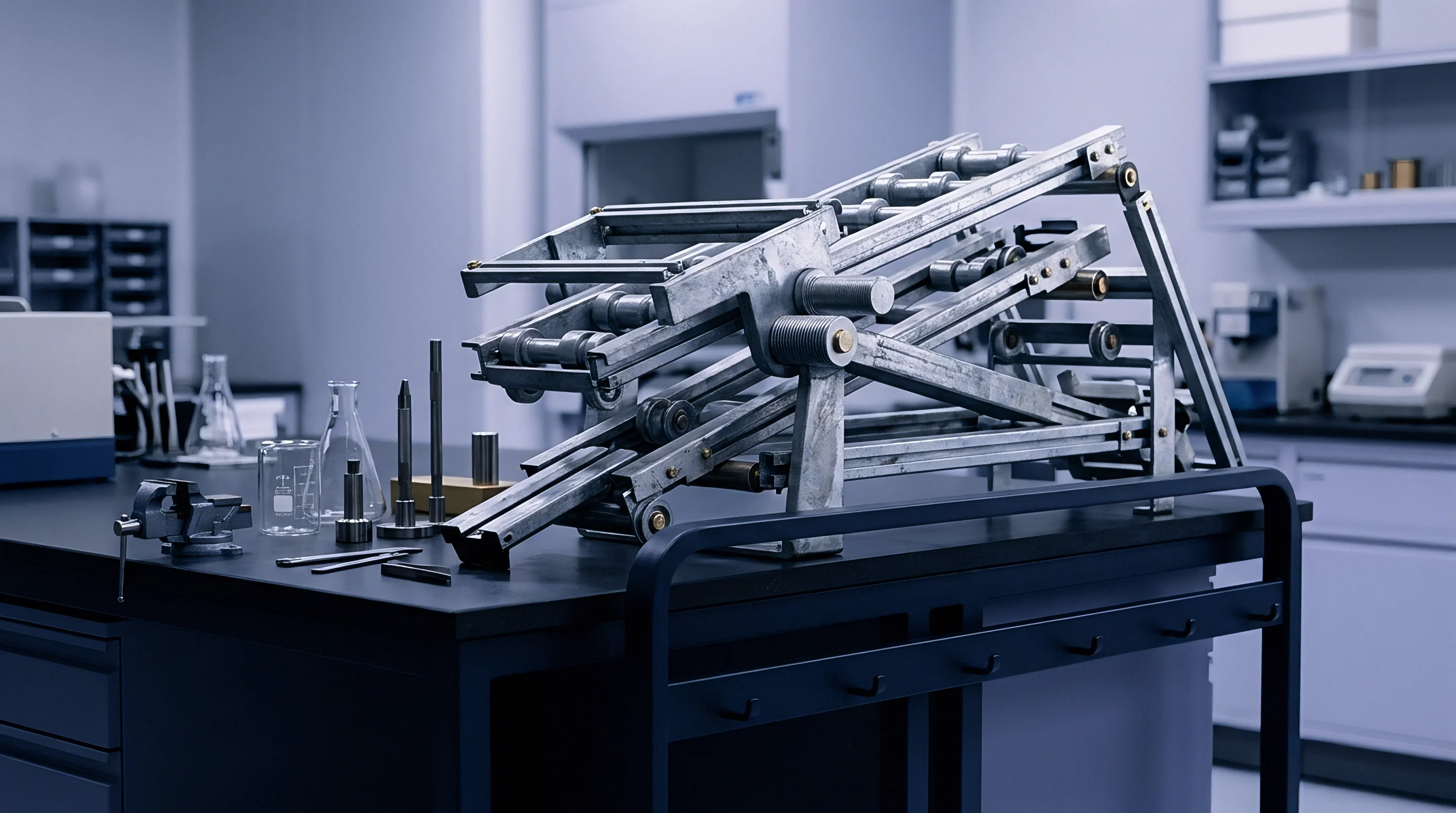
Converting modeled buffer lengths into workable plant layouts requires careful conveyor hardware selection. Hardware choices dictate backpressure forces, container stability, floor space usage, and maintenance overhead. High-speed lines generally use four main configurations: zero-pressure roller accumulation, continuous friction tabletop chains, alpine vertical spirals, or multi-lane mass flow tables.
Zero-pressure accumulation systems prevent compressive forces by dividing conveyor runs into individually controlled zones. Photo-eyes track product and drop drive power or apply pneumatic brakes when downstream zones fill. This eliminates container shingling, scuffing, and tipping on fast packaging lines.
However, zero-pressure systems carry a higher cost per linear meter than continuous friction conveyors and require formal financial justification.
Continuous friction accumulation uses low-friction chains (like acetal) sliding continuously under stationary product held by an index gate. It is cheaper to install and simpler to control, but line pressure increases linearly with queue length. On longer runs, this backpressure can crush light containers, damage labels, or draw enough motor current to trip thermal overloads.
Accumulation Mechanical Hardware Taxonomy
Hardware selection depends on container geometry, line speeds, and physical floor space. Multi-lane mass flow conveyors use funnel transitions to drop linear transit speeds while increasing unit storage per square meter. These systems are well-suited for stable cylindrical items like beverage cans or glass bottles running above one thousand units per minute.
Alpine accumulation towers are common on single-file lines with tight spatial footprints. They run continuous tabletop chain in vertical spirals, packing hundreds of meters of accumulation into a compact footprint. The trade-offs include elevation changes, complex guide rail setup, and chain tension limits that restrict total accumulated payload per drive.
| Technology Type | Spatial Density (Units/m²) | Max Line Speed (m/min) | Backpressure Force (N/Item) | Capital Cost Index (Base=1.0) | Maintenance Complexity |
|---|---|---|---|---|---|
| Continuous Friction Chain | 12 to 18 | 45 | 2.5 to 8.0 | 1.0 | Low |
| Zero-Pressure Roller (ZPA) | 15 to 22 | 60 | 0.0 | 2.8 | Moderate |
| Alpine Spiral Tower | 85 to 130 | 35 | 0.5 to 2.0 | 4.2 | High |
| Multi-Lane Mass Flow | 60 to 95 | 25 | 1.0 to 3.5 | 2.4 | Moderate |
| Dynamic Bi-Directional Table | 70 to 110 | 50 | 0.0 to 0.5 | 5.5 | High |
Zero Pressure Control Logic and Sensor Latency
Zero-pressure buffer performance depends directly on sensor placement and drive control logic. Singulation routines manage zone releases to prevent gaps or jams. Standard cascade logic releases zone one, waits for sensor clearance, and then fires zone two.
While stable, this sequential startup restricts discharge speed and creates gaps ahead of downstream machinery.
Pulse-release logic, by contrast, starts all occupied zones at once when downstream equipment requests product. Photo-eyes monitor spacing in real time to prevent collisions. Pulse-release reduces total buffer clearance times by twenty to thirty percent compared to standard cascade methods.
Standard mechanical accumulation hardware specifications defined under CEMA standards mandate that structural framing calculations account for total dynamic motor load under maximum packed line backpressure conditions.
Photo-eye response parameters need accurate tuning during line commissioning. Sensors are vulnerable to dust, variable ambient lighting, and reflective surfaces. If debounce timers are set too high, containers drift past zone limits before brakes engage, leading to collisions.
If set too low, minor container wobble or transparent sidewalls trigger false blockages and cause phantom line stops.

Friction Thermal Dissipation and Backpressure Limits
Continuous accumulation generates friction between moving chain links and stationary container bases. Extended accumulation on high-speed acetal or stainless chains raises local temperatures, accelerating wear on wear-strips and guide rails. That heat also softens thin plastic containers, increasing friction coefficients and compounding backpressure across the queue.
Backpressure damages product orientation. Allowable backpressure limits determine how long a continuous accumulation run can be before requiring zero-pressure breaks or dynamic relief tables. Total backpressure force is calculated as Fb = μ · N · m · g, where μ is the dynamic friction coefficient, N is accumulated unit count, m is container mass, and g is gravitational acceleration.
- Container Structural Integrity Limit specifies maximum crushing load thin-walled packages endure before experiencing permanent physical sidewall deformation.
- Chain Tensile Working Capacity defines peak allowable pull load on drive sprockets before chain elongation, pitch mis-engagement, or mechanical pin failure occurs.
- Drive Motor Thermal Dissipation Limit establishes maximum continuous slip time before drive motor electrical windings exceed thermal class limits.
- Stability Index for High Center-of-Gravity Items calculates maximum line deceleration or backpressure surge force an item tolerates without tipping over during mass queue packing.
Conveyor layouts should keep total accumulation pressure below twenty-five percent of package crush strength. If calculations show backpressure exceeding that limit, the line design must incorporate zero-pressure drives or dynamic recirculating tables.
Equipment vendors often claim their standard continuous transport chain handles high-speed accumulation without item damage, but field experience demonstrates that delicate packaging requires active pressure-relieving drive technology.
Discrepancy
Supplier proposals often present overly optimistic capacity numbers based on ideal conditions. Vendor proposals routinely rely on static spreadsheets to show that conveyor runs can handle station output, but they regularly ignore micro-stoppages, assume immediate operator interventions, and overlook container handling issues common during production ramp-up.
Vendor claims require independent verification through third-party engineering audits that check proposed layouts against historical operational logs. Reviewing performance data from similar installations highlights gaps between nameplate ratings and actual output. Finding these issues before signing contracts protects operational margins and avoids expensive layout changes later.
Auditing vendor models means digging into the raw parameter files of their discrete-event simulations. Suppliers frequently set stoppage frequencies well below industry norms or apply narrow normal distributions around repair times. These assumptions artificially shrink the required dynamic buffer size, letting vendors quote smaller footprints and lower equipment prices.
Vendor Capacity Claims versus Empirical Logs
Due diligence means validating vendor simulation parameters against actual PLC logs from operating plants. Discrepancies usually center on three areas: micro-stoppage counts, conveyor speed drop under load, and restart acceleration times. Suppliers often filter out stoppages under thirty seconds as negligible.
On high-speed packaging lines, however, those short stoppages account for up to forty percent of total efficiency loss.
Disputes frequently arise when key terms are left undefined in preliminary supplier agreements. Contractual documentation must explicitly define what constitutes an operational stoppage, establishing clear recording thresholds for simulation modeling inputs. Mandating that vendor dynamic models incorporate micro-stoppage records down to two-second durations prevents under-sizing accumulation runs.
Vendor models also tend to assume conveyors maintain constant linear speed under full load. In the real world, belt slip, mechanical play, and motor speed droop under heavy queues reduce belt speed by three to seven percent. This slows clearance rates, extends buffer drain times, and causes upstream blockages.
Factory Acceptance Testing Boundary Conditions
Factory Acceptance Testing must validate buffer capacity under dynamic stress before hardware leaves the vendor’s shop. Standard FAT protocols verify basic motor rotation, sensor inputs, and single-unit transfers on an empty or lightly loaded belt. These basic checks fail to prove whether buffers can handle mass flow accumulation and pressure relief under load.
Realistic FAT protocols simulate worst-case transient surges. Testers trigger artificial downstream stops while upstream machines run at one hundred ten percent of rated speed. The buffer must absorb arriving product for the agreed test duration without tipping containers, causing jams, or dropping sensor tracking.
- Full-Speed Accumulation Ramp Test verifies that transport tracks absorb incoming product mass at maximum nameplate line speed without triggering drive motor overload trips.
- Downstream Clearance Acceleration Stress Test confirms that empty buffer zones clear accumulated items at specified speed acceleration ratios upon line restart.
- Zero-Pressure Zone Cascade Delay Audit measures precise electrical and mechanical response latency across sensor zones during emergency stop and restart cycles.
- Product Surface Damage Rejection Threshold Inspection examines accumulated packaging for scuff marks, structural crushing, or label tearing after thirty minutes of continuous slip accumulation.
Data Capture Gaps in Operational Logs
Standard OEE systems regularly miss brief line disruptions. Most plant monitoring software polls machine status at intervals of five to sixty seconds. Stoppages shorter than the polling window go unrecorded, often showing up incorrectly as minor speed losses or unexplained availability drops.
Sizing buffers accurately requires high-speed event logging that captures PLC I/O changes at ten-millisecond resolution. High-speed logging records precise timestamps for sensor transitions, motor trips, and gate actuations. This granular data captures actual micro-stoppage patterns, allowing realistic parameter inputs for simulation models.
Engineers use these high-speed logs to generate stoppage duration histograms. Comparing empirical histograms against vendor simulation assumptions exposes the disconnect between theoretical performance and plant reality.
Equipment procurement contracts must stipulate that dynamic simulation models be calibrated using customer-validated historical downtime distributions prior to final layout freeze and capital authorization.

Outlay
Capital commitments for automated conveyor systems lock in plant layouts, foundations, and structural steel for decades. Signing purchase orders without dynamic buffer validation creates long-term operational and financial exposure. Industrial floor space carries substantial building and conditioning costs.
Oversizing conveyor runs inflates initial CapEx, drives up power draw, and restricts maintenance access. Undersizing cuts line throughput, creating ongoing revenue losses that far outweigh any upfront savings.
Because capital commitments lock physical space, establishing a formal stage-gate approval process for conveyor system funding prevents premature capital authorization. The approval workflow requires completing discrete-event simulation modeling, empirical operational parameter fitting, and supplier model auditing before releasing equipment procurement funds.
Financial analysis must weigh conveyor hardware costs against plant floor space valuations. Floor costs vary widely by facility type, from roughly two thousand dollars per square meter for dry manufacturing to upwards of fifteen thousand dollars per square meter for ISO Class 7 cleanrooms. Sizing buffers accurately has a direct impact on total facility footprint and structural investment.
Capital Allocation Framework for Buffer Footprint
Evaluating conveyor buffer investments requires a total life-cycle approach rather than simply looking at initial hardware cost. A life-cycle model accounts for equipment purchase price, building footprint cost, installation labor, annual drive motor energy use, routine maintenance, and expected downtime losses over a ten-year horizon.
Capital allocation comes down to balancing equipment expenditure against production uptime gains. Adding twenty meters of zero-pressure conveyor to a packaging line adds eighty thousand dollars in hardware, but recovers forty-five hours of lost production per year by buffering micro-stoppages. On a line generating ten thousand dollars in gross margin per operating hour, that investment pays for itself within two months of startup.
| Layout Strategy | Relative CapEx Cost | Footprint Utilization (m²) | Annual Lost Production Hours | 10-Year Total Cost of Ownership | Internal Rate of Return (%) |
|---|---|---|---|---|---|
| Undersized Static Model | Baseline (1.0x) | 120 | 380 | High (Severe Outage Penalty) | 11.2% |
| Oversized Conservative Buffer | 1.85x Baseline | 340 | 25 | Moderate (High Floor Cost) | 18.4% |
| Dynamic Simulation Optimized | 1.35x Baseline | 210 | 42 | Lowest Total Cost | 34.6% |
| Full Zero-Pressure System | 2.40x Baseline | 210 | 35 | High Initial Outlay | 21.0% |
Stage Gate Readiness Criteria before Vendor Selection
A formal stage-gate process governs capital spending throughout design. Stage Gate 1 clears initial concept layouts using baseline analytical queuing limits. Stage Gate 2 requires discrete-event simulation built on customer-validated downtime data.
Stage Gate 3 mandates auditing vendor bids against verified performance specifications. Stage Gate 4 releases final capital once equipment passes dynamic stress tests during Factory Acceptance Testing.
Clearing Stage Gate 2 requires proving that proposed layouts meet line availability targets within established confidence intervals. Engineering teams must show simulation results demonstrating that 95th percentile transient surges remain within conveyor buffer limits.
Because floor space carries recurring cost, Stage Gate 3 mandates that vendors submit digital discrete-event simulation models alongside physical design drawings. Plant engineering teams should validate sensor polling rates before locking conveyor acceleration profiles into CapEx line contracts. Internal engineering teams review supplier simulation code to verify that sensor latencies, acceleration ramps, and micro-stoppage distribution parameters accurately match site conditions.

Opportunity Cost of Oversized Conveyor Layouts
Oversized conveyor buffers create hidden operational costs well beyond initial purchase prices. Long conveyor runs hold large volumes of work-in-progress inventory between stations. High WIP raises working capital requirements, stretches production lead times, and increases scrap risk if upstream quality defects occur.
Plant floor layout directly affects material handling logistics. Excessively long conveyor lines create physical barriers across the floor, blocking forklift routes, operator walkways, and maintenance access points. Over-buffering wastes plant footprint.
Compact, dynamically optimized conveyor layouts free up floor space for future production lines, secondary packaging, or material storage, increasing revenue potential per square meter.
Engineering teams balance footprint reduction against availability risk through financial sensitivity modeling. Plotting conveyor buffer capital costs against downtime revenue losses identifies the investment point that maximizes net present value.
What unexpected control loop interactions emerge when continuous multi-lane accumulation zones transition into dynamic bi-directionally driven buffer tables during unannounced downstream power dropouts?