Basic Micro CT System Calibration Protocols for Industrial Polymer Inspection
Rigorous geometric alignment, beam pre-filtration, and traceable phantom calibration ensure sub-voxel dimensional accuracy in industrial polymer CT inspection.


Geometry
Spatial alignment inside an industrial micro-computed tomography cabinet defines the dimensional validity of every subsequent volumetric reconstruction. When examining injection molded polyamides or polyether ether ketone components, small misalignments between the X-ray source, the rotary stage, and the flat panel detector manifest as severe dimensional distortion. Spatial calibration starts by establishing the physical axis of rotation relative to the optical axis of the cone beam.
Center of rotation error appears when the rotational center of the turntable deviates from the central orthogonal projection line connecting the focal spot to the detector active area. An uncorrected center of rotation offset introduces crescent-shaped blur and double-edge artifacts at peripheral boundaries. Quantitative correction relies on scanning a precision multi-sphere artifact through a complete 360-degree rotation.
The acquisition software records the trajectory of each sphere centroid across projection angles, fitting an ellipse to extract seven kinematic parameters: source-to-axis distance, source-to-detector distance, detector horizontal and vertical shifts, detector roll, detector tilt, and stage slant.
A two-micron focal spot displacement during an eight-hour scan run shifts edge detection thresholds across thirty-millimeter polyoxymethylene gears by seven microns.
Detector non-orthogonality produces asymmetric voxel scaling along the vertical reconstruction column. If the detector tilts by a fraction of a milligram angle, vertical feature positions compress while horizontal features stretch. Calibrating geometric magnification involves calculating the exact ratio of the source-to-detector distance against the source-to-object distance.
Thermomechanical drift in the open-type microfocus tube housing alters these physical distances over production shifts. Tube warm-up cycles stabilize the cathode filament and transmission target before running kinematic alignments.

Kinematic Alignment Parameters
Industrial CT systems demand rigorous geometric verification to achieve metrological traceability. Table 1 outlines the standard kinematic adjustments and acceptable limits for precision polymer analysis.
| Kinematic Parameter | Measurement Method | Acceptable Deviation Limit | Primary Defect Manifestation |
|---|---|---|---|
| Center of Rotation Offset | Multi-sphere trajectory sinogram fit | Under 0.25 detector pixels | Double edges, peripheral elongation |
| Detector Roll Angle | Vertical twin-sphere shadow alignment | Under 0.05 degrees | Planar shear across reconstructed slices |
| Detector Out-of-Plane Tilt | Planar grid phantom projection matrix | Under 0.10 degrees | Non-linear vertical voxel scaling |
| Focal Spot Spatial Drift | Edge-spread function at ten minute intervals | Under 1.5 micrometers per hour | Modulation transfer function degradation |
| Stage Wobble and Runout | Capacitive sensor read during full revolution | Under 0.8 micrometers radial runout | Asymmetric point spread function |
Precision calibration requires dedicated multi-point reference artifacts designed for micro-focus geometries. These artifacts establish physical coordinates that tie reconstructed voxels directly to international measurement units.
- Multi-sphere carbon fiber rods secure ruby spheres at certified intervals with negligible thermal expansion coefficients. Spheres maintain sphericity under twenty nanometers.
- Silicon calibration grids integrate lithographically etched copper patterns to evaluate two-dimensional spatial distortion across the scintillator surface. Pitch accuracy remains within ten nanometers.
- Miniaturized step cylinders verify vertical scale factors across varying physical slice planes. Machined polyether ether ketone steps provide intermediate radiographic contrast without saturating the sensor.
Operators frequently execute geometric calibrations without allowing adequate stabilization time for the motorized manipulator stages. Skipping mechanical equilibrium causes continuous scale drift that invalidates downstream wall-thickness measurements across entire production lots.


Phantom
Metrological traceability in non-destructive testing rests on calibrated physical standards with known dimensional and attenuation properties. For polymer components, reference standards face unique challenges due to low X-ray attenuation, high thermal expansion coefficients, and mechanical compliance. Physical standards designed for dense metals produce severe photon starvation and excessive scatter when applied to low-density polymers.
Standards bodies establish explicit validation criteria for micro-focus dimensional metrology. VDI/VDE 2630 Part 1.3 defines protocols for determining the probing error and sphere distance error of coordinate measuring systems based on computed tomography. Calibrated ruby or silicon nitride spheres mounted on carbon fiber frameworks serve as the primary verification tools.
The system scans the ball bar or sphere array at multiple positions and orientations throughout the calibrated measurement volume. Software routines isolate the center of each sphere using three-dimensional sphere-fitting algorithms, calculating distance deviations against national metrology institute calibration certificates.
VDI/VDE 2630 Part 1.3 dictates that sphere distance errors remain within one-third of the component drawing tolerance across the entire calibrated measurement cylinder.

Why Do Low Density Standards Drift under Thermal Load?
Temperature fluctuations inside the inspection chamber alter the physical dimensions of polymer reference artifacts during extended scan sequences. Unfilled polymers like polypropylene and polyoxymethylene exhibit linear thermal expansion coefficients exceeding one hundred parts per million per Kelvin. Calibrating systems for polymer inspection requires reference phantoms fabricated from zero-expansion materials or temperature-monitored surrogate polymers.
Scanning a reference standard at twenty-three degrees Celsius while assuming standard room conditions of twenty degrees introduces a thirty-micrometer error across a one-hundred-millimeter dimension.
Structural validation uses reference phantoms with varying absorption characteristics. Step-wedge phantoms fabricated from the identical base polymer resin establish baseline radiographic attenuation levels. These step wedges quantify density steps, verify dynamic range, and calibrate signal response across differing section thicknesses.
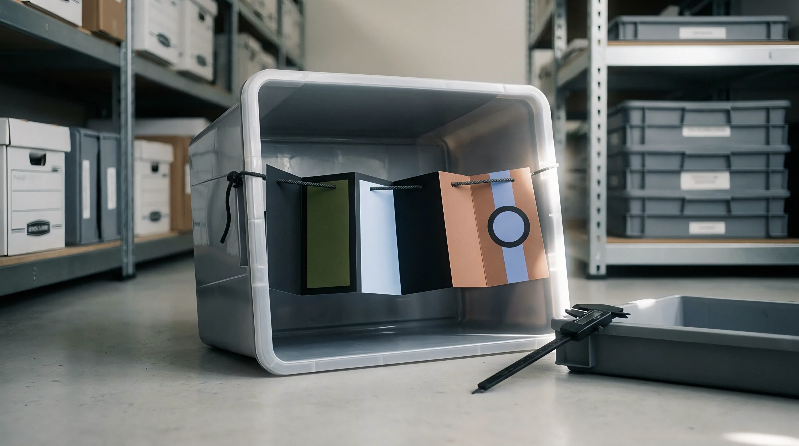
Reference Artifact Specifications
Standard selection depends on the target defect category and the inspection objective. The quality engineering dossier incorporates specific artifacts aligned to analytical demands.
- Probing size artifacts quantify systematic error in outer boundary determination. Ruby spheres with certified form deviation under fifty nanometers reveal non-linear edge shifts caused by partial volume artifacts.
- Probing form phantoms isolate system noise and reconstruction blur. The difference between minimum and maximum radial distance on a single sphere evaluates high-frequency background noise.
- Sphere distance ball plates assess spatial coordinate accuracy across three orthogonal axes. Carbon fiber plates hold fifteen or more spheres to measure anisotropic distortion across the cone-beam field of view.
- Internal void standards incorporate hollow glass microspheres embedded in thermoset resin. Calibrated hollows establish true detection limits for structural porosity analysis in structural injection molding.
Purchase specifications that omit traceable temperature-controlled ball bar runs allow suppliers to claim sub-micron metrological precision without proving volumetric scale stability under actual inspection cycle lengths.


Beam
Photons generated by industrial microfocus tubes form a polychromatic spectrum that interacts unevenly with organic materials. Low-energy photons absorb preferentially in outer material layers, shifting the average energy of the remaining spectrum toward higher values as the radiation penetrates deeper into the part. This phenomenon, known as beam hardening, distorts volumetric gray values, elevates surface apparent densities, and creates dark streaks between dense internal features.
Hardware pre-filtration removes low-energy X-rays before the beam reaches the polymer component. Thin sheets of aluminum, copper, or brass positioned at the tube exit window narrow the energy bandwidth. For low-density polymers such as polyethylene, unfilled polyamide, and acrylonitrile butadiene styrene, an aluminum filter thickness between 0.1 and 0.5 millimeters eliminates the softest photons without drastically reducing overall flux.
High-density polymers loaded with thirty to fifty percent chopped glass fibers or mineral fillers demand thicker filtration, often combining 0.5 millimeters of aluminum with 0.1 millimeters of copper to suppress scatter.
Uncorrected polychromatic beam hardening artificially elevates the apparent density of thin polymer exterior walls while deflating core attenuation values.
Flat-field normalization balances detector pixel sensitivities and corrects non-uniform beam intensity profiles across the flat panel. The calibration procedure acquires dark field images with the X-ray source deactivated to measure electronic noise and sensor dark current. The system then acquires bright field images at operating voltage and target current without an object in the trajectory.
Reconstructed projections normalize raw pixel intensities against these references. Flat-field calibration updates mitigate ring artifacts that originate from individual unresponsive or non-linear detector elements.

Pre-Filter Selection Guidelines
Matching the pre-filter material and thickness to the polymer formulation stabilizes the spectrum. Table 2 details standard pre-filter settings across major polymer categories.
| Polymer Classification | Typical Density Range | Recommended Tube Voltage | Hardware Pre-Filter Setup |
|---|---|---|---|
| Unfilled Polyolefins (PP, PE) | 0.89 to 0.96 g/cm3 | 50 to 80 kV | 0.1 mm Aluminum |
| Engineering Resins (POM, PBT, PA66) | 1.14 to 1.42 g/cm3 | 80 to 110 kV | 0.25 to 0.5 mm Aluminum |
| Glass Fiber Filled Resins (PA66-GF30) | 1.35 to 1.60 g/cm3 | 100 to 140 kV | 0.5 mm Aluminum + 0.1 mm Copper |
| High-Temperature Polymers (PEEK, PEI) | 1.28 to 1.45 g/cm3 | 90 to 120 kV | 0.3 mm Aluminum |
| Heavy Mineral Filled Composites (PPS-MD40) | 1.65 to 1.95 g/cm3 | 120 to 160 kV | 0.5 mm Aluminum + 0.25 mm Copper |
Mathematical beam hardening corrections supplement hardware filtration during volumetric reconstruction. Polynomial correction models map raw attenuation profiles against empirical transmission curves generated from step-wedge scans. The reconstruction algorithm calculates transmission ratios, adjusting the gray-scale linearity across thick cross-sections.
A supplier technician will state that modern reconstruction software algorithms completely eliminate the need for physical filtration on glass-filled polymer components.

Threshold
Extracting accurate dimensional metrics and porosity counts from reconstructed volume datasets depends entirely on surface edge determination. Gray value histograms of polymer scans exhibit partial volume effects, where voxels containing both polymer material and surrounding air display intermediate attenuation values. Miscalculating the boundary between solid material and background air skews every subsequent wall-thickness, void-volume, and coordinate measurement.
Basic global thresholding methods such as the ISO 50 percent approach calculate a single attenuation cutoff midway between the background air peak and the material substance peak. This approach assumes clean, bimodal histograms and uniform illumination across the entire volume. Industrial polymer components with variable wall thicknesses, internal ribs, and complex geometries violate these assumptions.
Local gradient edge detection algorithms address these limitations by evaluating the maximum directional derivative of gray values normal to the approximate part surface.

Where Does Edge Gradient Detection Break in Filled Polymers?
Fiberglass inclusions create localized attenuation spikes that confuse local gradient algorithms. In a thirty percent glass-filled polyamide, the high radiographic density of silica glass fibers generates micro-gradients that outshine the subtle boundary between the polyamide matrix and background air. The surface determination algorithm snaps to the outer fibers rather than the true resin envelope, causing erratic wall-thickness measurements across neighboring surface points.
Accurate calibration of the surface determination model relies on scanning an exact dimensional standard made of the identical resin grade. The operator runs surface extraction parameters on the known standard, adjusting the gradient search distance and background offset until the reconstructed surface matches the contact coordinate measurement machine baseline within sub-voxel tolerances.

Threshold Calibration Sequence
Calibrating edge detection models follows a strict sequential protocol to eliminate subjective operator adjustments during production quality control.
- Histogram normalization scales gray values against reference air and solid material zones to establish repeatable baseline endpoints.
- Global initial segmentation applies a preliminary threshold to generate an approximate three-dimensional surface mesh around the component envelope.
- Normal vector projection casts search rays perpendicular to the initial mesh outward and inward across a defined voxel search distance.
- Local gradient peak extraction identifies the precise point of maximum gray-scale slope along each individual ray vector.
- Surface smoothing and validation filters high-frequency outliers while preserving sharp structural corners and micro-porosity boundaries.
The question of how to automate local edge thresholds across multi-material assemblies containing both low-density silicone seals and rigid structural polyamides without manual operator intervention remains an active engineering challenge in production facilities.


Throughput
Integrating micro-computed tomography into serial polymer manufacturing operations creates immediate tensions between measurement precision and production cycle times. High-resolution metrology scans demand slow stage rotation, high projection counts, multiple frame averages, and lengthy detector integration periods. A comprehensive 2000-projection metrological scan can consume sixty minutes per part.
High-volume industrial lines require cycle times under three minutes per cycle.
Balancing throughput against calibration stability requires establishing structured recalibration intervals based on thermal and mechanical drift data. Industrial systems experience focal spot drift during continuous operation as target temperatures fluctuate. The calibration maintenance schedule partitions tasks into shift-based, weekly, and monthly activities based on component drift velocities.

Inspection Strategy Comparison
Operational strategies differ significantly between high-fidelity laboratory verification and high-speed in-line sorting. Table 3 breaks down calibration parameters across operational inspection modes.
| Inspection Mode | Projection Count | Integration Time | Calibration Verification Cycle | Measurement Uncertainty Band |
|---|---|---|---|---|
| First Article Metrology | 2400 to 3600 | 1000 ms per frame | Pre-scan ball bar verification | 1.5 to 3.0 micrometers |
| Statistical Process Control | 1200 to 1800 | 500 ms per frame | Daily center of rotation check | 4.0 to 8.0 micrometers |
| Automated In-Line Sorting | 400 to 800 | 100 ms per frame | Weekly geometric calibration | 12.0 to 25.0 micrometers |
| Fiber Orientation Mapping | 1800 to 2400 | 750 ms per frame | Shift-start flat-field update | 2.5 to 5.0 micrometers |
Detector pixel degradation accelerates under sustained X-ray exposure. Defective or non-linear pixels generate false void indications or spurious ring patterns in reconstructed polymer volumes. Automated bad pixel mapping routines identify and interpolate erratic sensor elements during dark and bright field calibrations.
Thermal stabilization time for the tube housing scales with the target power rather than the laboratory air conditioning turnover.
High-speed polymer inspection requires continuous monitoring of scan voxel stability. When scan times drop, photon noise increases, degrading the contrast-to-noise ratio. The edge detection algorithm struggles to identify subtle micro-voids in polypropylene moldings when noise levels exceed the attenuation gap between the polymer and void volumes.
Spatial resolution scales with the physical magnification geometry while measurement certainty scales with the signal integration budget.