Dynamic Shut Height Compensation Protocols for Precision Stamping Dies
Active in-die shut height compensation maintains bottom dead center repeatability within two microns, eliminating thermal scrap and doubling tooling life.
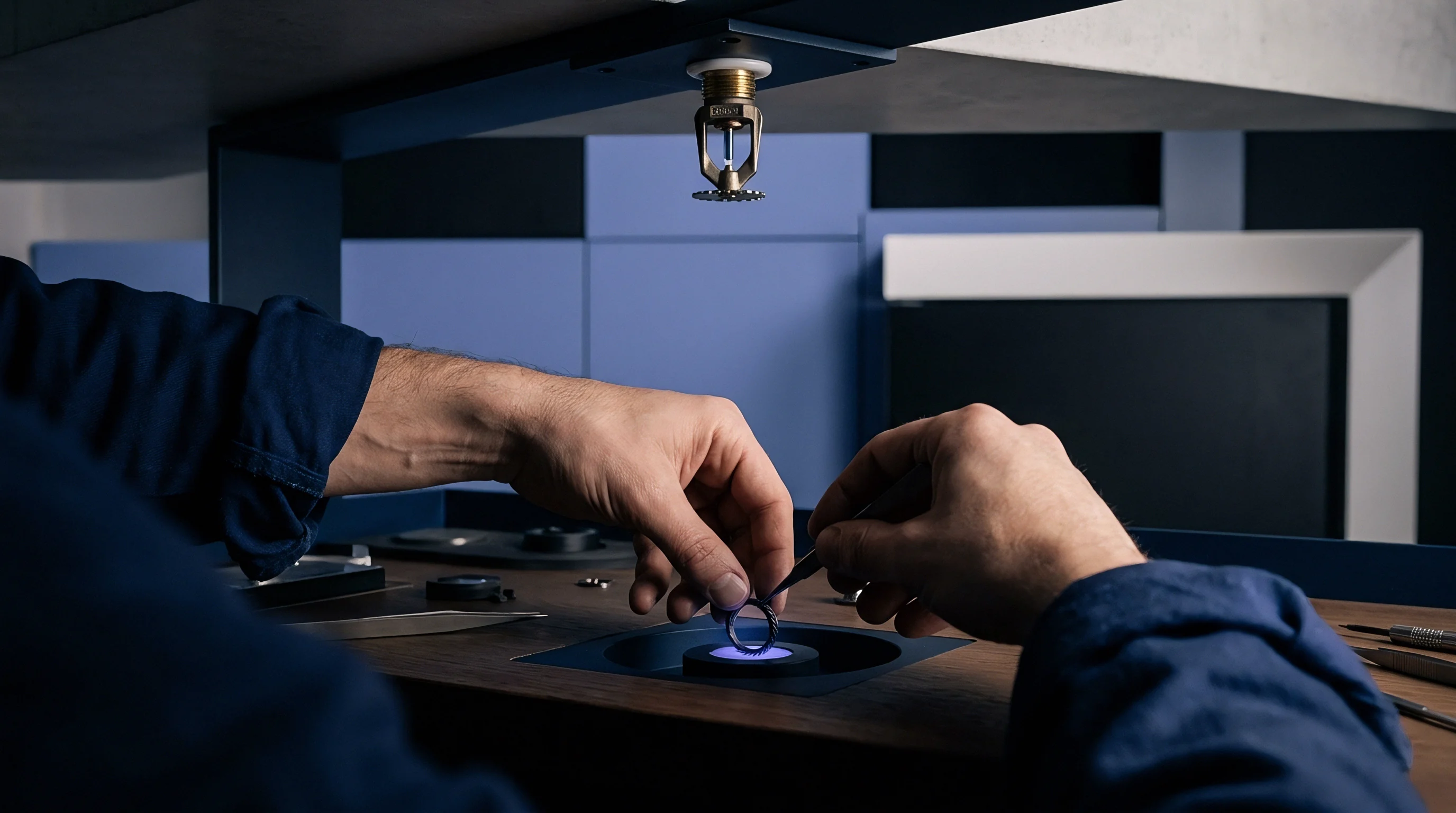

Deflection
Continuous dimensional drift at bottom dead center is standard in high-speed progressive blanking. Running uninterrupted at three hundred strokes per minute, a four-hundred-tonne straight-side press can shift its working shut height by twenty to seventy micrometers over an eight-hour shift. Frame stretch, crank pin bushing friction, connecting rod elongation, and thermal expansion of tooling inserts all contribute to the change.
When stamping micro-connectors, lead frames, or motor laminations with sub-millimeter terminal pitches, bottom dead center must remain repeatable within four micrometers to avoid burrs and uneven coin depth.
Press frame compliance causes instantaneous vertical flex proportional to stamping load. As punches hit ultra-high-strength automotive strip or phosphor bronze, the columns stretch in tension while the bed and slide flex elastically, pushing the stroke reversal point upward during blanking. High penetration forces also seat die components harder into the tool steel bolster plates, compressing every interface in the stack.
Reaching thermal equilibrium across high-speed equipment takes hours. Friction in main bearings, gib guides, and counterbalance cylinders pumps a steady heat flux into the upper frame. Because the press uprights and pitman arms heat at different rates, uneven expansion gradually tilts the slide out of parallel with the bedplate.
Bearing temperatures climbing twenty degrees Celsius lengthen pitman connections by thirty-five micrometers during five-stage lamination stamping.
Tooling assemblies create localized hot spots separate from the main press frame. Friction at the punches and die cavities, along with strip deformation, converts mechanical work directly into heat within the tool steel inserts ~ an effect that peaks at heavy coining and drawing stations along the die.
- Structural Column Elongation pulls the slide upward as ongoing tonnage builds up strain in the frame.
- Pitman Assembly Warming lengthens connecting links as heat dissipates from eccentric bushings.
- Die Bolster Compression causes micro-yield depressions under high-tonnage punches, gradually reducing effective penetration depth during long runs.
- Strip Gauge Thickness Fluctuation changes total breakthrough force between master coils, shifting frame deflection from cycle to cycle.
Variations in incoming strip stock disrupt this mechanical balance. A five-percent increase in coil thickness can boost total blanking force by eight to twelve percent, stretching the frame further and pulling the active penetration point off target. Uncompensated shut height drift chips punch tips, produces burrs beyond ISO 13715 limits, and forces operators to stop the line for manual shimming.

Gaging
Real-time metrology detects sub-micron positional shifts in the die space during full-tonnage cycling. While frame-mounted linear transducers capture overall column stretch, they miss in-tool flex and punch holder expansion. Getting reliable data requires direct in-die instrumentation at the tooling boundary.
Optical linear encoders built into four-pillar die sets measure relative motion between the upper and lower shoe plates. Glass scales reach resolutions down to fifty nanometers using noise filters isolated from the main drive motors. Because punching generates oil mist and metal particles, these optical sensors rely on positive air pressure seals to keep optics clean.
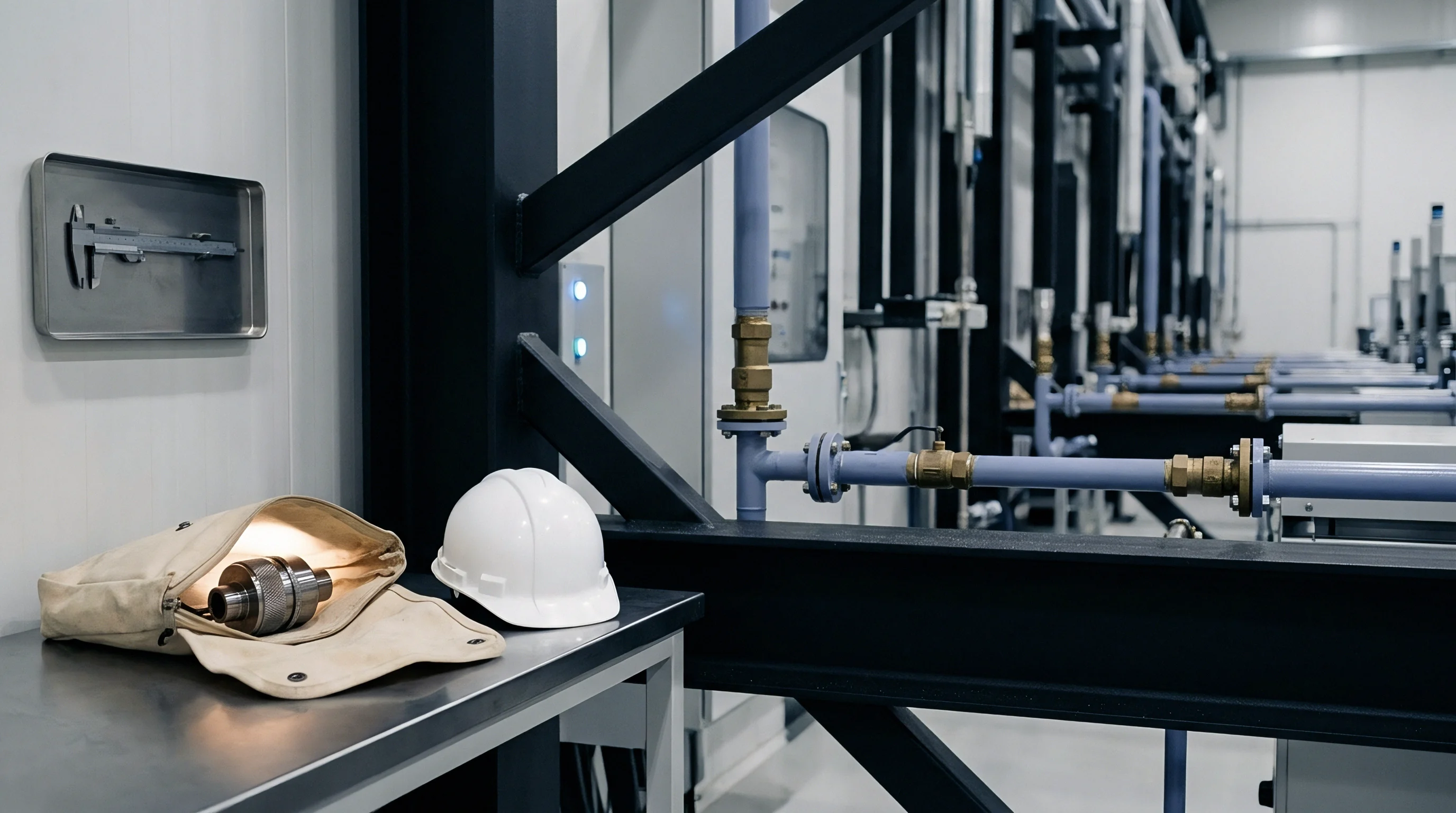
Can Piezoelectric Transducers Isolate In-Die Thermal Drift?
Piezoelectric load cells mounted under stripper plates or coining inserts measure dynamic force profiles at impact, tracking stroke-to-stroke peak tonnage at microsecond intervals. Signal analysis using fast Fourier transforms highlights penetration changes long before dimensional errors show up on parts. However, standard piezo sensors cannot track slow thermal drift, as charge leakage degrades static readings over time.
| Sensor Architecture | Measurement Target | Sampling Rate | Positional Accuracy | Environmental Sealing |
|---|---|---|---|---|
| Optical Glass Scale | Die Shoe Relative Position | 50 kHz | ±0.1 µm | IP67 with Air Purge |
| Piezoelectric Load Cell | Station Tonnage Profile | 100 kHz | ±1.0 N | Hermetic Welded Housing |
| Eddy Current Probe | Punch Retainer Clearance | 25 kHz | ±0.5 µm | Oil and Fluid Proof |
| Fiber Optic Interferometer | Stripper Bottom Dead Point | 200 kHz | ±0.05 µm | Optical Lens Purge |
Eddy current displacement sensors monitor the bottom face of the upper punch retainer plate. These inductive probes run continuously in lubricant-soaked dies without drifting, provided calibration factors account for how temperature affects magnetic permeability in alloy tool steels between twenty and eighty degrees Celsius.
Per DIN 8651 inspection limits, total kinematic deviation across slide guidance surfaces must remain within specified parallelism boundaries during operational velocity runs.
Periodic manual micrometer checks on stamped parts provide basic offline feedback, but cannot capture real-time thermal or dynamic drift during press operation.

Wedge
Active mechanical actuators adjust component stack height while the press is running. These systems place hardened tool steel ramps beneath sub-bolsters or individual station inserts. Servo-driven ball screws and planetary gearboxes move precision-ground wedges horizontally, shifting the station vertically with sub-micron resolution.
Ramp angles between two and five degrees combine strong mechanical advantage with self-locking behavior under dynamic shock loads. A three-degree taper holds its setting without back-driving when a fifty-tonne impact strikes the station during a twenty-millisecond stroke. Drive motors decouple through torsionally rigid disc couplings so punch vibration does not ruin encoder bearings.
Hydraulic micro-capsules present another option. These short-stroke cylinders rely on fast closed-loop servo valves to meter oil beneath high-pressure pistons. Because hydraulic fluid compresses noticeably under four hundred bar pressures, system stiffness drops unless pressure compensation adjusts on every stroke.
| Actuator Mechanism | Stiffness Rating | Step Resolution | Response Time | Load Holding Capacity |
|---|---|---|---|---|
| Servo Mechanical Wedge | 1200 N/µm | 0.2 µm | 15 ms | 1500 kN Self-Locking |
| Hydraulic Capsule | 450 N/µm | 0.5 µm | 4 ms | 800 kN Valve Maintained |
| Piezo Stack Actuator | 800 N/µm | 0.01 µm | 0.5 ms | 200 kN Continuous Voltage |
| Eccentric Motor Bushing | 1000 N/µm | 0.4 µm | 25 ms | 1200 kN Mechanical Stop |
Rigidity determines how accurately a compensation assembly performs. Hardened D2 or CPM-1V tool steel ground to Ra 0.2 helps eliminate stick-slip friction during sub-micron adjustments.
- Signal Acquisition Phase averages bottom dead center displacement across five consecutive strokes to filter out signal noise.
- Offset Vector Calculation calculates the precise vertical correction needed inside the motion controller.
- Rotary Drive Execution drives the brushless servomotor through a planetary gearbox to turn the horizontal drive screw.
- Mechanical Ramp Displacement translates horizontal screw movement into vertical height adjustments across the ground wedge faces.
- Position Confirmation Readout checks secondary glass scale linear encoders to confirm position before the next stroke.
Coatings like diamond-like carbon or molybdenum disulfide prevent galling and cold welding on sliding wedge faces. When dealing with punch bounce, high mechanical rigidity achieves better stability than relying solely on electronic filtering.


Feedback
Closed-loop control systems adjust tool height without pausing production. Signal sampling occurs during the non-contact portion of the stroke, between ninety degrees past bottom dead center and two hundred seventy degrees top dead center. Making corrections while punches are in the strip causes severe side loading and breaks punch tips.
Feedforward loops compensate for changes in press speed. Accelerating from one hundred to six hundred strokes per minute thickens the hydrodynamic oil film in sleeve bearings, forcing the ram downward by fifteen to forty micrometers. The controller monitors flywheel speed to retract wedges preemptively, acting before thermal sensors even register the shift.
Mechanical wedge adjusters executing corrections within thirty milliseconds prevent cumulative part dimensional drift during speed ramp transitions.
Thermal changes take hours to develop, whereas mechanical cycles occur in milliseconds. Adaptive control algorithms separate rapid cyclic force spikes from slow frame expansion, relying on proportional-integral loops for steady thermal drift and feedforward tables for speed changes.

Which Correction Frequency Prevents Mechanical Resonance?
Adjusting tooling position on every single stroke risks exciting natural resonant frequencies in the bolster and die set. Averaging data over ten to twenty cycles suppresses sensor noise and prevents limit-cycling. Micro-adjustments are then made in half-micrometer increments during the upstroke window.
- Moving Average Window Sizing filters out electrical noise generated by heavy drive motors.
- Stroke Window Synchronization limits motor motion commands to the upstroke between one hundred twenty and two hundred forty crank degrees.
- Thermal Profile Calibration applies historical expansion data tailored to specific tool steels and die geometries.
- Velocity Feedforward Mapping pre-positions wedges during press acceleration to offset hydrodynamic bearing growth.
Controls engineers still debate whether closed-loop systems should regulate for constant peak blanking tonnage or hold absolute tool position during long progressive runs.
Yield
Holding a stable bottom dead center point yields clear economic benefits. Stamping precision electrical terminals requires tight control over crimp height and carrier strip twist; a drift of just eight micrometers can create out-of-spec crimp tabs, triggering vision system rejections and downstream assembly jams.
Uncompensated dies require frequent manual intervention. Operators have to stop the press, inspect strip samples, loosen bolster clamps, adjust pitman screws, and run test pieces. Every adjustment costs twenty to forty minutes of uptime and creates scrap while the tool thermally stabilizes again.
| Operating Mode | Parts Per Shift | Scrap Rate | Die Regrind Interval | Setup Downtime Per Week |
|---|---|---|---|---|
| Uncompensated Manual Adjust | 115,000 | 4.2% | 450,000 Strokes | 6.5 Hours |
| Thermal Steady-State Only | 132,000 | 1.8% | 750,000 Strokes | 3.0 Hours |
| Real-Time Closed-Loop Wedge | 158,000 | 0.15% | 1,400,000 Strokes | 0.5 Hours |
Tool life improves when penetration depth remains constant. Punches entering carbide die cavities past design limits experience accelerated abrasive wear and edge chipping. Keeping penetration variation within two micrometers can double the time between tool regrinds, lowering annual tooling costs.
Scrap reduction saves material, especially with expensive stock like beryllium copper or silver-plated alloys. Plants using active compensation show consistent first-pass yields across three shifts, unaffected by shop floor temperature changes or coil-to-coil variations.