Quantifying Mooney Wall Slip Velocity Parameters across Multiple Capillary Die Geometries
Quantifying Mooney wall slip parameters across multiple capillary die radii prevents costly extrusion tooling rework and stabilizes polymer processing cash margins.


Conduit
Extrusion processing of highly filled polymer compounds, elastomers, and concentrated suspensions relies on accurate boundary condition modeling within the die land. Polymer melt flowing through narrow channels experiences high wall shear stresses that break interfacial adhesive bonds between the fluid matrix and the metal surface. This phenomenon creates a thin fluid layer of reduced viscosity or localized phase separation at the boundary, manifesting macroscopically as wall slip.
Ignoring slip velocity leads directly to miscalculated pressure drops, inaccurate die swell predictions, and incorrect channel sizing in production tooling.

Capillary Flow Mechanics and Wall Boundary Physics
Fluid deformation inside a cylindrical channel operates under a non-uniform velocity field dictated by the radial stress distribution. Maximum shear stress occurs at the outer boundary, where molecular chain orientation and stress-induced migration force lower-molecular-weight species toward the metal wall. Pressure drops change rapidly.
When interfacial stress surpasses a critical boundary threshold, the traditional zero-slip condition invalidates completely. The total volumetric flow rate measured at the exit becomes an additive combination of bulk viscoelastic deformation and interfacial slip translation.
Capillary dies with length-to-diameter ratios below sixteen introduce severe entrance pressure distortion that skews wall shear stress calculations.
Determining the true deformation behavior requires isolating slip displacement from pure fluid shear. Standard single-die capillary measurements report an apparent shear rate that assumes zero velocity at the internal wall boundary. When slip occurs, the apparent shear rate overstates the true shear rate experienced by the polymer core.
Disentangling these two components demands systemic testing across multiple capillary channel diameters while holding the true wall shear stress constant.
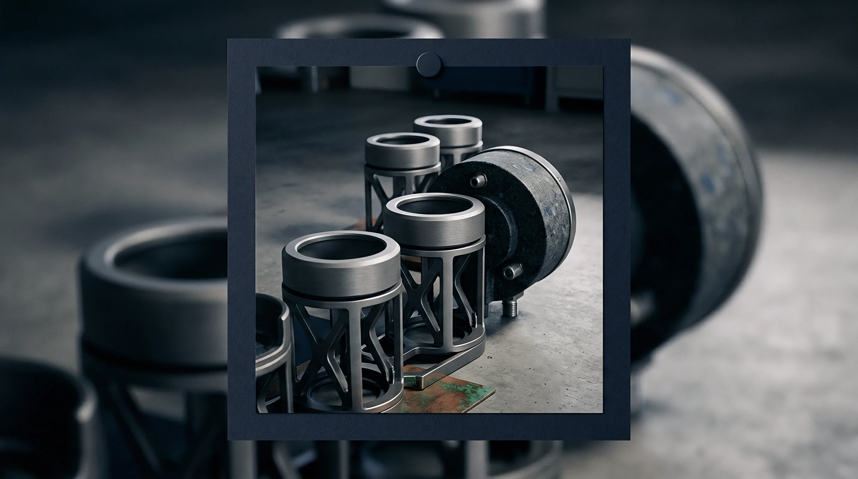
Bagley Entrance Corrections and Pressure Drop Extraction
Total pressure measured upstream of a capillary die includes significant energy losses from fluid acceleration and convergence at the channel entrance, along with elastic energy storage and exit pressure drops. Wall slip alters velocity profiles. Extracting true wall shear stress requires removing these end losses through Bagley correction procedures.
Raw pressure measurements collected across dies of identical diameter but varying capillary land lengths are plotted against the length-to-diameter ratio at fixed flow rates.
| Die Set ID | Capillary Radius (mm) | Length-to-Diameter Ratios | Entrance Angle (degrees) | Bagley Pressure Loss (MPa) |
|---|---|---|---|---|
| Die Set A | 0.50 | 5, 10, 15, 20 | 90 | 1.42 |
| Die Set B | 1.00 | 5, 10, 15, 20 | 90 | 1.18 |
| Die Set C | 1.50 | 5, 10, 15, 20 | 90 | 0.95 |
| Die Set D | 2.00 | 10, 16, 24, 30 | 180 | 0.82 |
Linear extrapolation of the total pressure to a length-to-diameter ratio of zero yields the entrance pressure drop. Subtracting this entrance loss from total measured pressure isolates the fully developed wall shear stress within the capillary land. Melt elasticity complicates extraction.
Running tests across shorter dies without Bagley corrections propagates entrance pressure errors directly into wall shear stress calculations, skewing slip parameters by up to thirty-five percent. Whether wall slip phenomena depend on capillary entrance geometry when die entrance angles vary from sharp entry to tapered conical transitions remains a key area of empirical investigation.


Aperture
Capillary geometry selection governs the resolution of wall slip parameter extraction. Evaluating flow rates across at least three distinct capillary radii allows numerical isolation of slip velocity from bulk fluid shear rate. Classical Mooney methodology relies on plotting apparent wall shear rate against the inverse of the capillary radius at constant wall shear stress values.

Classical Mooney Analysis across Varied Die Radii
The mathematical foundation of wall slip extraction expresses the apparent shear rate as the sum of the true wall shear rate and a slip velocity term divided by the die radius. Capillary geometry defines shear. At a fixed wall shear stress, true wall shear rate remains invariant regardless of channel size.
Plotting apparent shear rate on the vertical axis against the inverse radius on the horizontal axis yields a straight line with a slope equal to four times the wall slip velocity.
Linear regression yields slope values. Calculating slopes across multiple wall shear stress levels generates a comprehensive slip velocity function. Radii variations isolate velocity.
Deviations from linearity in Mooney plots indicate experimental scatter, temperature drift, or non-linear slip behavior where slip velocity depends on channel dimensions due to pressure-dependent fluid properties.

Generalized Wall Slip Parameterization and Non-Linearities
Filled polymers frequently exhibit power-law slip behavior, where slip velocity scales non-linearly with wall shear stress. Modeling this response requires extracting the slip coefficient and power-law slip exponent from experimental Mooney curves. At high shear stresses, severe slip leads to fluid detachment and surface melt fracture, altering extrudate quality.
- Radii Selection Ratio ~ Capillary radii span at least a three-fold range to ensure adequate spread on the horizontal axis of the Mooney plot.
- Length Standardization ~ Die length-to-diameter ratios remain above sixteen after Bagley corrections to maintain fully developed laminar flow conditions.
- Temperature Stability ~ Barrel zone temperatures stay within zero point two degrees Celsius of setpoint to eliminate thermal viscosity shifts.
- Pressure Bounds ~ Operating pressures stay below fifty megapascals to avoid pressure-induced viscosity increases during testing.
A three-point die radius variation at constant wall shear stress isolates true slip velocity within a five percent margin of error above two hundred kilopascals.
When negative slip velocities emerge from mathematical extraction, the fluid exhibits pressure-dependent viscosity or shear-induced filler depletion near the boundary. Adjusting for these non-linearities requires generalized Mooney methods that incorporate pressure dependency factors or wall layer depletion thickness models into the governing boundary equations. Die land surface finish determines the onset of wall slip.


Shear
True fluid deformation cannot be determined without correcting raw rheometric data for wall boundary movement. Uncorrected shear rates lead to overestimating melt viscosity, which misguides polymer compound development and production die design. Separating true deformation rate from slip translation yields the actual fluid constitutive properties required for accurate computational fluid dynamics simulations.

Can Wall Slip Extraction Prevent High Shear Capital Waste?
Industrial extrusion lines operating at high throughput speeds consume substantial energy and raw material. Operating production tooling designed without slip parameter integration causes severe pressure mismatches, leading to thermal degradation, gross melt fracture, and dimensional out-of-tolerance extrudates. Capital committed to tooling modifications, line downtime, and material scrap quickly accumulates when wall slip is neglected during initial die design.
| Compound Type | Filler Loading (wt%) | Wall Shear Stress (kPa) | Extracted Slip Velocity (mm/s) | Power-Law Slip Exponent |
|---|---|---|---|---|
| Unfilled HDPE | 0 | 150 | 2.1 | 1.82 |
| EPR Rubber Compound | 35 | 180 | 6.4 | 2.15 |
| Highly Filled PVC | 50 | 220 | 14.8 | 2.84 |
| Fluoropolymer Masterbatch | 5 | 120 | 18.2 | 1.45 |
Quantifying slip velocity parameters enables die engineers to adjust die land length and channel taper angles precisely. Matching the internal die geometry to the fluid’s slip profile reduces excessive head pressure, lowers melt temperature rise, and stabilizes extrudate dimensions. The investment in multi-die capillary testing pays back directly through immediate yield improvements during extrusion line commissioning.

Rabinowitsch Corrections under Slip Boundary Conditions
Correcting apparent shear rate for non-Newtonian fluid behavior requires applying the Weissenberg-Rabinowitsch-Mooney equation. Fluid velocity profiles inside the capillary channel flatten as shear-thinning increases. Subtracting the wall slip velocity from the apparent flow rate precedes the calculation of the power-law index slope.
ISO 11443 compliance for capillary rheometry mandates explicit reporting of entrance angle geometries to prevent uncorrected shear stress distortions from invalidating compound specifications.
Executing Rabinowitsch corrections on raw data containing uncorrected wall slip generates invalid non-Newtonian flow indexes. Viscous heating shifts viscosity. Isolating slip velocity first ensures that the logarithmic slope of wall shear stress versus corrected shear rate reflects genuine bulk fluid shear thinning.
Ignoring this sequence produces false power-law indexes that distort numerical simulations of profile extrusion dies, resulting in tooling modifications that fail to rectify production profile defects.

Derivation
Physical parameters driving wall slip velocity require systematic numerical extraction from experimental capillary rheometer datasets. Processing raw extrusion data into robust mathematical models demands consistent execution steps to isolate viscous heat dissipation, pressure dependencies, and transducer calibration offsets.

Non-Isothermal Effects and Viscous Heat Dissipation
High shear flow through small capillary channels generates significant internal heat due to viscous dissipation. Temperature rise lowers fluid viscosity near the die wall, creating a thermal soft layer that mimics physical wall slip. Distinguishing thermal thinning from mechanical wall slip requires monitoring fluid temperature rises at the exit or using adiabatic flow correction models.
Entrance pressure dominates calculations. Conducting rheological trials at multiple shear rates requires verifying that temperature increases remain under two degrees Celsius across all tested die geometries. Excess thermal generation skews Mooney plot slopes, leading to inflated slip velocity values.
Implementing temperature correction factors stabilizes extracted slip coefficients across broad shear rate windows.

Pressure Dependency of Wall Slip Coefficients
High axial pressure inside long capillary channels compresses polymer melt and increases fluid viscosity, while simultaneously enhancing interfacial adhesion at the wall surface. Wall slip velocity decreases as hydrostatic pressure increases. Extracting pressure-independent slip parameters requires utilizing capillary die sets with varied diameters but constant length-to-diameter ratios, or employing counter-pressure capillary rheometry setups.
- Mount the target capillary die set into the rheometer barrel zone and heat to the specified test temperature for forty-five minutes.
- Load the polymer sample into the barrel, perform manual compaction, and allow a ten-minute thermal equilibration period.
- Drive the rheometer piston at predetermined volumetric flow rates to collect raw pressure transducer readings across four capillary diameters.
- Perform linear regression on total pressure versus length-to-diameter ratio data to compute entrance pressure drop values.
- Subtract entrance pressure losses to obtain true wall shear stress figures across all experimental flow rates.
- Construct Mooney plots of apparent shear rate against inverse radius for each constant wall shear stress value.
- Calculate linear regression slopes to derive wall slip velocity parameters as a function of wall shear stress.
Die suppliers state that standard catalog rheometer dies deliver sufficient accuracy without custom length-to-diameter sets, blaming material batch variability whenever profile extrusion dies fail to meet specified pressure drop targets.


Scrap
Uncertainty in wall slip parameters translates directly into physical scrap, prolonged die commissioning cycles, and working capital erosion. Extrusion plants operating high-capacity lines consume hundreds of kilograms of polymer compound per hour during tooling qualification trials. When die channels are sized using non-slip assumptions for compounds that slip significantly, the resulting profile dimensions fall outside dimensional tolerance bands immediately upon startup.

Quantifying Landed Scrap Costs from Tooling Mismatch
Scrap generation directly degrades gross manufacturing margins. Converting raw polymer compound into unsellable purge and off-spec profile stock consumes energy, machine operator hours, and plant floor capacity without producing revenue. Scrap accumulation drains liquidity.
Tooling rework cycles require removing the extrusion die, wire-EDM recutting or polishing die lands, re-installing the tooling set, and re-running material trials.
Consider a profile extrusion facility qualifying a custom filled-PVC architectural profile running at three hundred kilograms per hour. The raw material landed cost equals two euros and forty cents per kilogram. Initial die design utilized bulk viscosity data without wall slip extraction.
During qualification, the die produced an asymmetrical profile wall thickness due to localized slip, generating four hundred kilograms of scrap per trial run before shutdown. Re-machining the die land required three rework iterations over three weeks, consuming twelve total testing hours and generating three thousand six hundred kilograms of scrap. Total direct material scrap cost reached eight thousand six hundred forty euros, while lost line production time consumed twenty-eight thousand euros of machine margin contribution.
Incorporating multi-die capillary rheometry to quantify slip parameters prior to tooling manufacture requires a single test dossier costing eighteen hundred euros, completely eliminating the three rework cycles and preserving operational cash flow.

Worked Arithmetic of Extrusive Scrap and Cash Conversion
Extrusion profile scrap carries both direct material costs and carrying costs associated with raw material inventory commitments. Material bought on net-thirty-day payment terms sits in warehouse storage before consumption, then moves through scrap purging, and eventually undergoes re-grinding or disposal before invoice settlement. Tooling errors inflate working capital.
- Profile Cross-Section Distortion ~ Wall slip variation across asymmetrical channels causes uneven flow velocity, warping complex profile sections upon exit.
- Surface Sharkskin Defect ~ Exceeding critical wall shear stress triggers periodic stick-slip transitions, creating micro-roughness on exposed extrudate surfaces.
- Die Land Sizing Errors ~ Sizing die land length without accounting for slip translation results in excessive pressure drop and reduced line speed.
- Purge Volume Accumulation ~ Machine shutdowns required for tooling adjustments consume excess purge compound to clear thermal degradation from barrels.
Uncorrected wall slip velocity during die scale-up shifts profile dimensions outside critical tolerances within thirty minutes of steady-state extrusion.
Material yield governs gross margin. Supply contracts with automotive and medical OEMs contain standard quality rejection clauses specifying maximum allowable dimensional variances under ISO 1101 standards, where failure to demonstrate validated rheological parameter extraction shifts full financial liability for scrapped production lots directly onto the extruder.


Facility
Acquiring advanced capillary rheometry equipment and specialized multi-geometry die sets represents a distinct capital expenditure allocation. Financing these physical assets requires balancing facility debt service against operational yield gains and reduced tooling rework costs. Debt covenants restrict leverage.
Equipment lenders evaluate asset coverage ratios, equipment depreciation schedules, and working capital reserves before approving senior secured credit facilities for laboratory infrastructure.
Capital Expenditure Sizing for High-Pressure Capillary Rheometry
Procuring a twin-barrel capillary rheometer equipped with low-range and high-range pressure transducers, automated die changing assemblies, and precision multi-radius die sets requires a total capital outlay ranging between one hundred twenty thousand and two hundred forty thousand euros. Facility drawdown funds equipment. High-pressure die tooling sets fabricated from tungsten carbide or hardened tool steel add significant incremental expenditure per material formulation.
| Facility Component | Capital Cost (EUR) | Financing Instrument | Tenor / Term | Annual Debt Service (EUR) | Covenant Headroom Impact |
|---|---|---|---|---|---|
| Twin-Barrel Capillary Rheometer | 165,000 | Asset Finance Lease | 5 Years | 36,200 | Fixed Charge Cover -0.12x |
| Multi-Radius Die Geometry Set | 32,000 | Unsecured Equipment Loan | 3 Years | 11,800 | Leverage Ratio +0.08x |
| Rheology Laboratory Infrastructure | 45,000 | Working Capital Facility | Revolving | 2,700 | Current Ratio -0.05x |
| Data Extraction Software Suite | 18,000 | Vendor Tech Term Loan | 2 Years | 9,600 | Cash Reserves -18,000 EUR |
Quantifying financial returns relies on analyzing the net reduction in scrap rates and tooling modification expense. Allocating capital to inline or offline rheological characterization assets shortens customer qualification lead times, freeing up inventory working capital tied up in safety stock during prolonged product launches.

Debt Covenant Sensitivity to Tooling Rework and Material Yields
Commercial lending agreements enforce financial performance covenants, including minimum Debt Service Coverage Ratios, maximum Net Debt to EBITDA leverage caps, and minimum Current Ratios. Unexpected scrap surges caused by uncorrected extrusion wall slip directly erode operating EBITDA, compressing covenant headroom and risking default provisions on credit facilities.
Integrating Mooney wall slip extraction into standard compound qualification dossiers stabilizes gross manufacturing margins and insulates operating results from unexpected tooling rework expenses. Demonstrating rigorous material characterization protocols lowers credit risk profiles during annual facility reviews with commercial lenders. Capillary die geometry quantification protects operational cash flows at the die face, maintaining covenant compliance and preserving growth capital availability for expanding production capacity across core manufacturing operations.