Thermal Environment Monitoring Requirements for Coordinate Measuring Machines
Unmonitored thermal gradients expand CMM frames and workpieces, requiring continuous multi-sensor logging to keep measurement uncertainty inside drawing tolerance.

Drift
An ambient shift of 2.2 °C across an eight-hour morning cycle moves the bridge geometry of an uninsulated bridge coordinate measuring machine by fourteen micrometers along its horizontal traverse. Precision manufacturing facilities frequently treat metrology rooms as isolated sanctuaries, yet thermal flux penetrates walls through structural conduction, duct vibration, and doorway convection. Production scheduling pushes newly machined components straight from cutting fluids into the measurement envelope.
The resulting temperature divergence between the reference scale and the measured component creates immediate volumetric distortion.
Dimensional measurement assumes a standard state defined globally by ISO 1 as 20 °C. Every drawing dimension, geometric tolerance, and calibration certificate ties its validity to this exact baseline. When a shop floor machine or laboratory unit operates at 23.5 °C without active logging, reading errors grow in proportion to length and material expansion coefficients.
Steel expands 11.5 micrometers per meter. Aluminum expands twenty-three micrometers per meter. Granite expands six micrometers per meter.
These differential expansion rates mean that a granite machine structure holding a steel linear scale and measuring an aluminum prism experiences three divergent expansion vectors simultaneously. Without continuous thermal tracking, the inspection software assumes geometric purity while the physical axes deform. The CMM accepts bad parts.
An ambient excursion of 1.8 °C beyond the 20 °C datum on an eight-hundred-millimeter aluminum casting consumes sixty-two percent of a twenty-five-micrometer profile tolerance.
Standard Reference Temperature Baseline
Calibrating a coordinate measuring machine under ISO 10360-2 establishes maximum permissible error of length measurement, designated as E0,MPE. Machine builders specify this baseline performance under strict ambient envelopes, typically 20 °C plus or minus 1.0 °C, with temporal gradients held below 0.5 °C per hour. Machining facilities rarely sustain these boundaries.
Plant heating, ventilation, and air conditioning equipment cycles on deadbands spanning 2.0 °C to 4.0 °C, causing structural hysteresis in granite slabs and bridge castings.
The linear thermal expansion coefficient of structural granite rests at 6.5 x 10^-6 per Kelvin in metrology design specifications. This figure originates from laboratory dilatometry testing of medium-grain black granite across 120 quarry core samples evaluated in 2018. If quartz concentrations shift between twenty percent and thirty-five percent within a specific machine bed, the true coefficient moves between 5.8 x 10^-6 per Kelvin and 7.2 x 10^-6 per Kelvin.
Applying an unverified default nominal value inside compensation software introduces residual length errors over long travel axes.
Linear scales experience mounting stress when attached to disparate substructures. A glass scale clamped rigidly to a steel spar adopts an effective expansion coefficient determined by adhesive shear stiffness and fastener pitch. If ambient temperatures oscillate rapidly, the spar responds faster than the surrounding granite mass.
The machine controller applies compensation values based on air temperature sensors while the structural spar remains bent in thermal stress.

Spatial and Temporal Gradients
Thermal variations divide into spatial distributions across the operating volume and temporal changes over production shifts. Vertical thermal stratification represents the most prevalent spatial defect in metrology enclosures. Warm air accumulates near the ceiling, creating vertical gradients exceeding 1.5 °C per meter of height.
Air temperature stratification dictates vertical uncertainty. The Z-axis ram travels through this thermal layer during inspection runs. At top stroke, the probe head and ram absorb heat from high-mounted lighting and ceiling air stratification.
At bottom stroke, near the granite table, cold air pooling cools the stylus assembly. The resulting differential bending along the vertical column induces Abbe errors that mathematical software packages cannot correct without multi-point vertical sensor data.
Temporal gradients disrupt structural equilibrium through cyclic thermal waves. Plant air handler cycling trips tolerance. When supply diffusers blow conditioned air directly onto an axis, surface skin temperatures plunge while the structural core stays warm.
This uneven distribution produces thermal curling, where beams bow toward the cold side. The inspection lot stops immediately. Unmonitored heat flow across the coordinate frame converts tight machining tolerances into systemic scrap and undetected assembly interference.

Array
Transducer networks transform environmental guesswork into verifiable spatial boundaries. Metrology managers often rely on a single wall-mounted thermometer to authorize daily quality releases. A single sensor tracks neither the internal structural state of the coordinate frame nor the thermal lag of heavy workpieces.
Instrumentation plans demand discrete sensor placements across three physical zones: the machine structure, the ambient air volume, and the part under evaluation.
Four-wire platinum resistance detectors, designated as PT100 elements, represent the working standard for metrology monitoring. These sensors deliver resolution down to 0.01 °C with calibration uncertainties bounded inside 0.05 °C. Thermocouples lack the long-term stability needed for precision inspection cells, displaying drift from junction corrosion and lead wire thermal gradients. Modern digital sensor networks communicate over RS-485 or industrial Ethernet busses, piping synchronized temperature arrays directly into the secondary coordinate calculation engine.
| Measurement Target | Transducer Type | Mounting Location | Sampling Interval | Target Uncertainty |
|---|---|---|---|---|
| Granite Base Table | PT100 Class 1/10 DIN | Drilled central well, 50mm depth | 60 seconds | ±0.03 °C |
| X-Axis Bridge Beam | PT100 Thin Film Surface | Centerline neutral bending axis | 30 seconds | ±0.05 °C |
| Y-Axis Guide Rail | Matched Thermistor Pair | Opposed drive and idler guideways | 30 seconds | ±0.04 °C |
| Z-Axis Vertical Ram | PT100 Surface Contact | Mid-span quill housing | 15 seconds | ±0.05 °C |
| Ambient Envelope Low | Aspirated Air Sensor | Table height, 300mm offset | 10 seconds | ±0.08 °C |
| Ambient Envelope High | Aspirated Air Sensor | Z-axis maximum travel height | 10 seconds | ±0.08 °C |
| Production Workpiece | Magnetic Surface RTD | Thickest cross-section core area | 60 seconds | ±0.05 °C |
| Sensors calibrated annually against secondary water-triple-point cells under ISO 17025 accreditation. | ||||
Transducer Placement across Machine Axes
Securing temperature elements directly to machine components demands mechanical isolation from parasitic heat paths. Drive motors on high-speed linear gantry systems emit thermal plumes during aggressive acceleration cycles. Placing an air sensor directly downstream of an axis servo drive reads motor exhaust rather than environmental ambient air.
Structural sensors attach to neutral mechanical planes using thermally conductive ceramic filled epoxies or spring-loaded mechanical fixtures. Fasteners must never distort precision guideways during torque application.
Ambient air sensors demand radiation shields and low-velocity mechanical aspiration. Stagnant air pockets around large machine pillars produce artificial thermal lag in unventilated transducers. Conversely, direct exposure to HVAC supply diffusers induces rapid electrical noise that software filters misinterpret as room instability.
Aspirated tubes drawing air at 0.5 meters per second isolate sensor tips from local radiant fields, measuring true ambient gas temperature.
What Thermal Gradient Invalidates Calibration Records?
Calibration logs lose legal and technical standing the moment spatial gradients breach boundaries established in machine acceptance dossiers. ASME B89.4.10360.2 defines acceptable operating bands through thermal error index calculations. When horizontal gradients exceed 0.5 °C per meter, or vertical gradients surpass 1.0 °C per meter, calibration mathematical models break down.
Sensor hardware configurations fail through predictable installation mistakes:
- Unshielded lead routing creates inductive noise spikes when signal lines share wire trays with servo motor power cabling.
- Thermal bridging through brackets transfers ambient sheet metal temperature directly into a granite base sensing point, corrupting base thermal readings.
- Inadequate surface bonding leaves an insulating air cushion between the RTD brass sheath and the measured machine frame. Single-point surface contact generates a twenty-minute response lag.
- Uncalibrated sensor extension cables alter lead resistance in two-wire or three-wire circuits, generating false systematic temperature shifts of up to 0.4 °C per ten meters.
The measurement result becomes void. Uncontrolled drafts alter bridge geometry. Deploying resistance temperature detectors across the volumetric envelope locks the spatial boundary so inspection records reflect physical part dimension rather than structural machine expansion.

Soak
Workpieces entering an inspection room from machining cells carry vast quantities of kinetic and chemical thermal energy. Cutting operations, solvent degreasing, and ultrasonic washing elevate workpiece cores to temperatures between 30 °C and 55 °C. Placing a hot sixty-kilogram steel transmission housing onto a cold granite coordinate measuring machine creates an intense, localized heat exchanger. Thermal energy drains through the clamping points into the machine table while radiating into the bridge guideways above.
The air boundary layer delays conduction. Workpiece soaking defines the mandatory latency duration during which a component passively exchanges thermal energy with surrounding environmental air until internal temperature gradients decline below critical measurement thresholds.
Compliance with ISO 10360-2 clause 6.3 cancels inspection acceptance when temporal temperature variation exceeds 1.0 °C per hour.
Deep underground mining tunnels share identical thermodynamic stabilization delays, where massive rock faces continue transferring trapped heat into circulating ventilation air for months after excavation. Metrology chambers experience this same structural sluggishness on a smaller dimensional scale. Thick cast iron retains thermal history long after ambient air registers equilibrium.
Convective Exchange and Volumetric Equilibration
Thermal stabilization rates follow Newton’s law of cooling, governed by surface area, thermal conductivity, component mass, and convective air velocity. The soak period figure of fourteen hours for a 150-millimeter solid aluminum block rests on convective heat transfer coefficient models at 0.15 meters per second air velocity published in machine tool research from 2021. Forced ventilation velocities above 0.8 meters per second reduce this window to 5.5 hours, while enclosing the block in cardboard packaging extends equilibration beyond twenty-eight hours.
| Material Class | Max Wall Thickness | Initial Part Temp | Ambient Air Temp | Required Soak Duration |
|---|---|---|---|---|
| Structural Steel Plate | 25 mm | 32.0 °C | 20.0 °C | 4.5 Hours |
| Structural Steel Billet | 120 mm | 38.0 °C | 20.0 °C | 11.0 Hours |
| Cast Iron Engine Block | 45 mm | 28.0 °C | 20.0 °C | 7.5 Hours |
| Aerospace Aluminum Spar | 15 mm | 35.0 °C | 20.0 °C | 2.5 Hours |
| Solid Aluminum Tooling | 150 mm | 40.0 °C | 20.0 °C | 14.0 Hours |
| Titanium Turbine Disc | 60 mm | 30.0 °C | 20.0 °C | 9.0 Hours |
| Polymer Fixture Board | 50 mm | 26.0 °C | 20.0 °C | 16.5 Hours |
Can Expansion Compensation Mask Thermal Drift?
Software packages claim complete mitigation of non-standard temperatures through real-time mathematical scaling. The operator types the nominal coefficient of thermal expansion into the controller, clips a single magnetic sensor to the part surface, and triggers the probe routine. This workflow assumes the workpiece maintains uniform temperature throughout its volume and expands isotropically.
Complex geometries with variable cross-sections falsify this assumption. A thin-walled section cools in thirty minutes while a heavy mounting boss remains hot for six hours, bending the part during measurement.
Thermal compensation software cannot correct turbulence. Operators must clear sequential soaking milestones before mounting parts:
- Stage incoming pallets inside the metrology enclosure unstacked with minimum 100mm air gaps between adjacent workpieces.
- Strip all protective wax, shipping plastic, and residual cutting oils that impede convective thermal exchange.
- Connect calibrated contact probe sensors to both the thinnest web and heaviest core sections of the workpiece.
- Log differential readings across component sensors until delta values stay inside 0.15 °C for three consecutive thirty-minute polling cycles.
- Transfer the component to the CMM table using insulated lifting slings to prevent body heat transfer from operator hands.
The operator quarantine holds the pallet. Metrology enclosures achieve stable measurement only when workpiece core thermal inertia matches scale thermal inertia before touch trigger cycles commence.


Audit
Inspection records face intense diligence during tier-one aerospace and automotive quality audits. Quality managers show clean calibration stickers on CMM covers while failing to produce continuous environmental log histories corresponding to measured serial numbers. A calibration certificate demonstrates machine compliance only during the specific twenty-four-hour window when the calibration service provider ran step gages across the table.
The calibration certificate expires on shift when environmental limits collapse.
The default fifteen percent rule of thumb for uncompensated thermal drift in total CMM uncertainty budgets lacks rigorous cross-facility empirical defense. The figure appears frequently in plant manuals without supporting test data across varied building configurations. In this situation, a prudent buyer demands a physical twenty-four-hour artifact drift test under site ambient swings rather than accepting the synthetic calculation.
Shop floor draft patterns shift faster than machine thermal correction algorithms calculate structural expansion.

Documentary Reconciliation of Thermal Logs
Auditors correlate electronic temperature databases against physical part inspection timestamps. If serial number 84920 shows a final buy-off timestamp of 14:22 on a Tuesday, the diligence examiner pulls the ambient and machine scale temperature records for that exact second. A gap in logging data indicates unmonitored processing, invalidating the inspection record under aerospace quality systems.
Environmental records must link dynamically to coordinate measuring files, appending raw sensor readings directly into the inspection dossier header.
A complete thermal compliance dossier incorporates four core documentary assets:
- Continuous environmental data logs recording ambient air temperatures at multiple heights, structural temperatures, and relative humidity at intervals not exceeding sixty seconds.
- Sensor calibration pedigrees showing unbroken traceability to national metrology institutes for every RTD and thermistor deployed in the cell.
- Thermal error assessment logs generated via periodic drift tests using stable zero-expansion artifacts like Zerodur or carbon-fiber ball bars over full production cycles.
- Part soaking verification records documenting the arrival timestamp, staging location, and surface-to-core thermal convergence prior to CMM table placement.
Environmental Envelope Verification
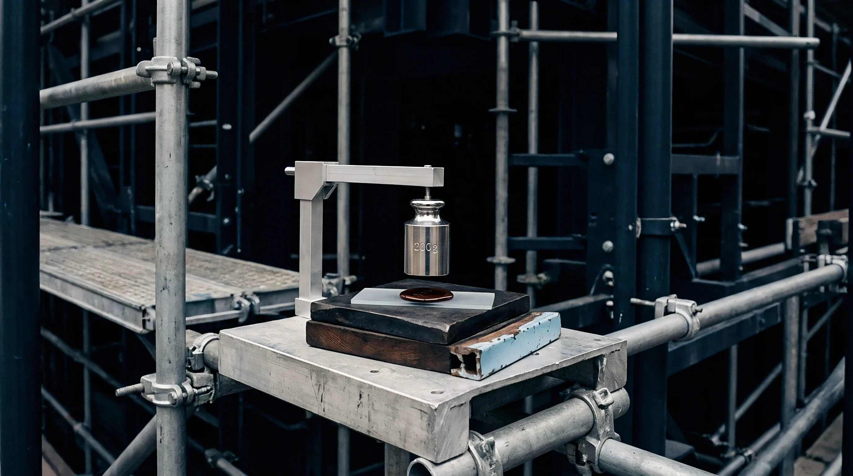
Verifying enclosure capability requires continuous drift analysis under real production conditions. ASME B89.4.10360.2 provides procedures for assessing thermal environment adequacy. Technicians mount a reference sphere or stable artifact in the measurement volume and inspect its coordinates repetitively over forty-eight hours without software thermal compensation enabled.
The resulting coordinate drift tracks raw thermal distortion induced by facility room cycles.
The QA manager halts final release. Invoking ISO 14253-1 decision rules shifts the thermal uncertainty band directly against the tolerance limit, shrinking the acceptable manufacturing zone by the entire unmonitored temperature deviation.
Exposure
Financial exposure from unmonitored thermal environments concentrates at commercial boundaries between suppliers and prime contractors. A precision machining supplier ships titanium aerospace brackets verified as conforming on a shop-floor CMM operating at 24.5 °C. The receiving customer inspects the identical lot inside an environmentally controlled laboratory stabilized at 20.0 °C. The parts fail incoming inspection on hole position tolerances. The supplier faces scrap costs, expedited remanufacturing expenses, and payment withholding while shipping dates expire.
Disputes over part acceptance resolve through measurement uncertainty evaluations governed by ISO 14253-1. When thermal monitoring data is absent, the party attempting to prove conformance must expand their uncertainty band by the maximum conceivable thermal expansion error. This expansion wipes out acceptable manufacturing tolerance windows, converting borderline good parts into contractual rejects.
| Enclosure Grade | Temperature Band | Temporal Stability | Capital Cost Range | Operating Cost Profile |
|---|---|---|---|---|
| Production Shop Floor | 18.0 °C to 28.0 °C | ±2.5 °C / Hour | Minimal capital layout | Severe scrap and dispute risk |
| Modular Shop Enclosure | 19.0 °C to 23.0 °C | ±1.0 °C / Hour | $45,000 to $85,000 | Moderate HVAC power demand |
| Class 2 Inspection Lab | 19.5 °C to 20.5 °C | ±0.4 °C / Hour | $120,000 to $220,000 | Continuous dual-stage chilling |
| Class 1 Metrology Vault | 19.8 °C to 20.2 °C | ±0.1 °C / Hour | $350,000 to $700,000 | Laminar air displacement system |
Production Gate Governance
Scaling volume without clear thermal stage gates multiplies quality system debt. Expanding machine capacity by purchasing high-speed coordinate measuring machines delivers zero added throughput when parts sit quarantined over thermal disputes. Operational readiness requires clear sequencing of capital and procedure.
Leadership must mandate temperature logging infrastructure before releasing capital for automated CMM loading cells.
A manufacturing cell clearing stage-gate review must show thermal capability matching part tolerance requirements. If drawing tolerances demand ten micrometers of total profile accuracy, unmonitored thermal expansion must not consume more than one micrometer of the total uncertainty budget. Achieving that ratio on steel components longer than five hundred millimeters requires either active thermal compensation backed by certified sensor arrays or enclosed class 2 laboratory facilities.

Facility Capital Allocation Sequence
Facility engineering teams frequently prioritize aesthetic room panels over air distribution aerodynamics. Standard ceiling diffusers blow localized high-velocity air streams directly into machine gantries, causing localized thermal distortion far worse than stagnant warm air. Air exchange systems require laminar displacement designs that introduce conditioned air through perforated floor panels or low-velocity wall diffusers at velocities below 0.15 meters per second.
Investing in structural enclosure insulation, airlocks, and aspirated sensor arrays yields immediate returns by preventing false part rejections. Capital allocation plans must treat thermal monitoring networks not as optional metrology accessories, but as governing operational infrastructure that dictates factory output legitimacy. Whether component manufacturers will absorb secondary environmental testing enclosures or absorb perpetual contractual disputes over thermal drift during summer peak cycles remains undetermined across Tier 1 supply agreements.