Resolving Multi Cavity Thermal Dissipation Dynamics in Dynamic Laser Line Optical Profilometry
Resolving multi-cavity thermal drift in laser profilometry requires combining laminar optical air purges with real-time housing thermistor compensation.


Microclimate
High-speed inline laser line profilometry relies on strict geometric phase matching. Triangulation sensors map surface topology by projecting a coherent laser sheet onto a target and imaging the reflection onto a two-dimensional matrix detector. When deployed over hot multi-cavity tooling ~ such as high-cavitation injection molding dies or precision-forged electronic enclosure components ~ the air in the measurement zone degrades.
Heat spilling from mold pockets creates thermal plumes, boundary layer stagnation, and sharp spatial temperature gradients that alter the air density along the optical path.
Optical refraction varies directly with air density, which changes with temperature, pressure, and gas composition. Around multi-cavity tooling, heat trapped near cavity walls, step features, and apertures causes micro-scale density fluctuations. As light traverses these temperature gradients, its refractive index shifts dynamically.
This ray bending skews the sensor’s triangulation calculations, producing artificial Z-height shifts, broadened edge phantoms, and false flatness warpage that have nothing to do with true target geometry.
Thermal spatial gradients exceeding three degrees Celsius per centimeter across an unpurged cavity clear aperture introduce Z-axis optical triangulation errors that scale non-linearly with standoff distance.
Greater standoff distances give thermal pockets more opportunity to deflect optical rays. When sensors operate sixty to three hundred millimeters above a part to clear conveyance systems, light passes through an extended thermal boundary layer. Stagnant convective cells settle inside deep cavities, warmed by radiant sidewalls and floor convection, forming micro-climates that ambient shop air rarely breaks up.
Higher scan speeds worsen the effect. At line rates above two hundred profiles per second, the sensor transitions between thermal zones in fractions of a millisecond. Moving from an external web plate at forty degrees Celsius into a deep cavity pocket containing stagnant air at eighty-five degrees Celsius shifts the refractive index abruptly.
The profiling engine interprets this ray deflection as physical surface topography, introducing systematic errors that can quickly exceed tight drawing tolerances.

Thermal Air Boundary Layer Ray Deflection Mechanisms
Light travelling through non-isothermal air follows Fermat’s principle of least time, curving toward cooler, denser regions. At standard optical wavelengths, the refractive index of air drops by roughly one part per million for each degree Celsius increase in local temperature. Over a three-hundred-millimeter optical path with localized temperature spikes forty degrees Celsius above ambient, total optical path length errors become substantial compared to sub-micron or single-digit micron tolerances.
Triangulation relies on exact alignment between the laser diode axis, the target focal spot, and the receiver optical centerline. Refractive index gradients perpendicular to the optical path cause rays to curve continuously. Deflection along the projection path changes where the laser hits the part, while deflection along the return path shifts where the image lands on the CMOS array.
Together, these shifts distort the software’s transformation matrices, yielding false Z-axis height readings.
Deep multi-cavity tooling produces asymmetric thermal boundary layers. Sidewalls radiate heat inward while warm air rises through the center, turning stagnant air pockets into weak thermal lenses. These air lenses distort line thickness and cross-line energy distributions.
When the sensor registers broadened or skewed Gaussian profiles, peak-detection algorithms lose accuracy, creating spatial aliasing around sharp features.
- Refractive index phase distortion shifts the apparent location of projected laser lines as density gradients deflect incoming and reflected light paths.
- Spatial peak detection asymmetry alters the calculated centroid of laser line profiles as non-uniform air densities distribute light unevenly across CMOS pixels.
- Thermal boundary layer shear introduces high-frequency optical phase noise when rising convective plumes pass through the sensor’s imaging path.
- Internal cavity heat trapping creates static high-temperature pockets that shift baseline Z-axis calibration between adjacent tooling positions.
In high-throughput inline inspection, thermal air disturbances look virtually identical to machining errors or mold shrinkage. Systems running uncompensated profilometry risk rejecting good parts or passing out-of-spec components. Correcting these optical errors requires physical mapping of the thermal air environment within multi-cavity features before processing raw profile data.
Ignoring cavity micro-climates leaves inspection systems prone to false out-of-tolerance alarms that follow ambient factory heating and cooling cycles rather than actual part defects.


Chassis
Internal heat generation inside high-power laser line sensor housings creates another major source of dimensional instability. Modern profilometers integrate laser drivers, blue or red semiconductor diodes, high-speed CMOS imagers, and embedded FPGA processors into single sealed enclosures. These electronics dissipate between eight and twenty-five watts during continuous operation.
That heat must conduct through internal structural mounts to the outer housing to keep the laser diode within its operating limits.
Heat from internal electronics creates temperature gradients across the optical bench. Structural mounts holding receiver lenses, folding mirrors, and beam-shaping optics expand as thermal energy flows through the chassis. Micron-level expansions alter the distance between receiver lenses and detector planes, shifting the pixel-to-angle calibration matrix and causing Z-axis offset and scale-factor drift in raw profile streams.
| Material Configuration | Coefficient of Thermal Expansion (ppm/K) | Thermal Conductivity (W/m·K) | Optical Mount Drift at 10 K Delta (µm) | Calculated Z Height Measurement Shift (µm) |
|---|---|---|---|---|
| Standard Anodized Aluminum 6061-T6 | 23.1 | 167.0 | 4.62 | 18.48 |
| Nickel-Iron Alloy Invar 36 Structural Core | 1.2 | 13.9 | 0.24 | 0.96 |
| Carbon Fiber Reinforced Polymer Composite | 0.8 | 45.0 | 0.16 | 0.64 |
| Cast Iron Tooling Frame Reference Structure | 10.5 | 52.0 | 2.10 | 8.40 |
Housing material selection determines mechanical stability under shifting thermal loads. Aluminum dissipates heat effectively but expands significantly with temperature. As internal temperatures rise from a cold boot to thermal equilibrium, non-uniform housing expansion strains the optical bench plates, moving the laser emitter relative to the imager and altering calibrated geometry.
Radiant heat from hot tooling complicates these internal thermal profiles. Radiant energy striking one side of the sensor enclosure creates an uneven temperature distribution. The face exposed to the mold expands faster than the unexposed faces, warping the housing frame and tilting the receiver lens assembly.
An optical axis tilt of only a few arcseconds introduces several micrometers of measurement error at typical standoff distances.
Internal sensor electronics heat dissipation combined with external radiant heating induces multi-axis optical alignment drift that distorts spatial profiling accuracy across long production runs.
Laser diode performance also shifts with temperature. As junction temperatures rise, central emission wavelengths shift upward at 0.25 to 0.35 nanometers per degree Celsius. Narrowband bandpass filters placed before the CMOS imager to block ambient shop light attenuate these shifted wavelengths.
This attenuation lowers signal-to-noise ratios, reduces peak intensity on target surfaces, and increases measurement uncertainty on low-reflectivity materials.
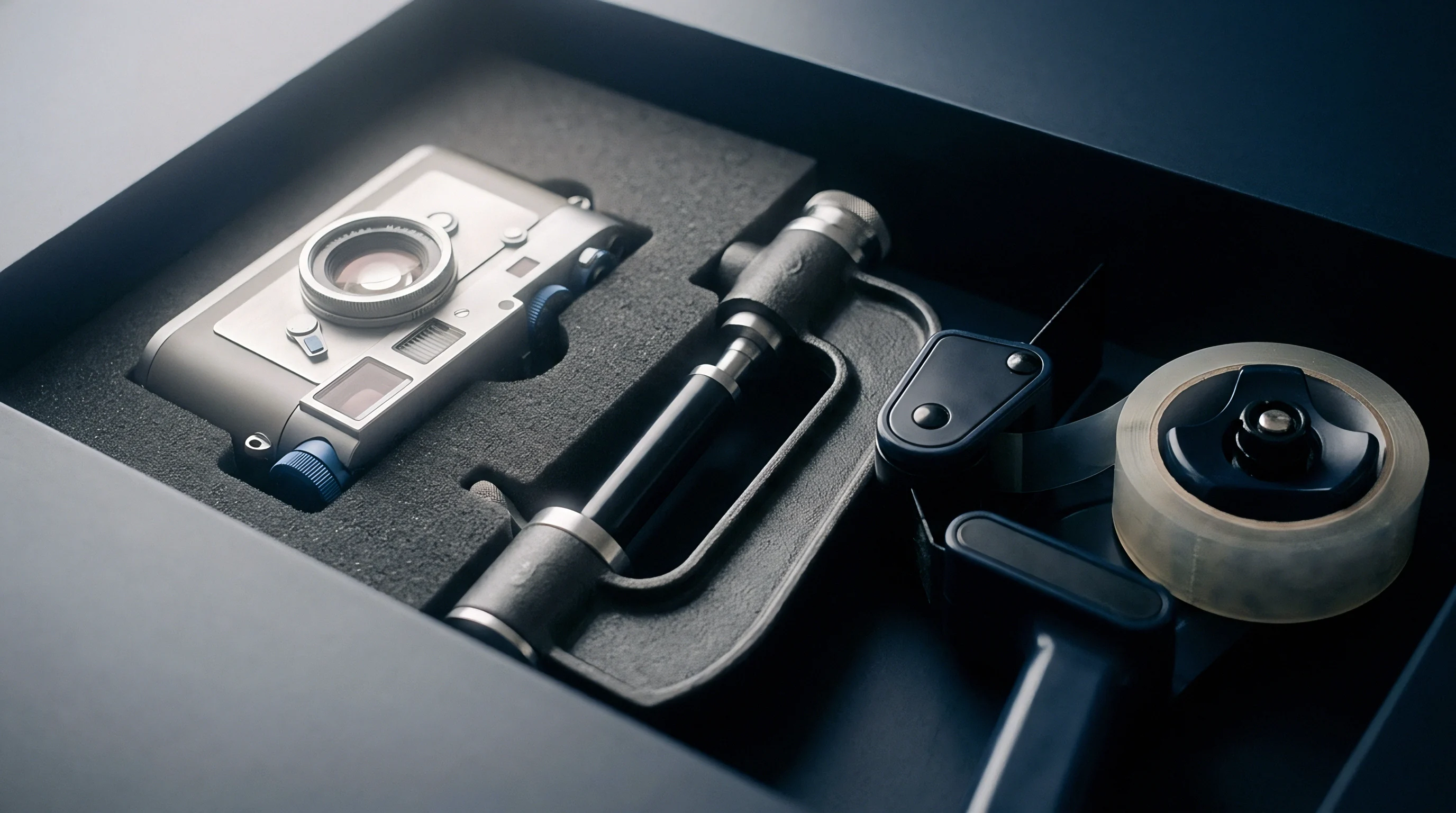
Chassis Mechanical Distortion and Optical Alignment Mechanics
Optical triangulation relies on stable positioning between internal components. Receiver lens cells mounted to aluminum plates shift as temperatures fluctuate. Movement along the optical axis alters effective focal length and magnification.
Shifts as small as two micrometers move the focused spot across multiple pixel columns, corrupting spatial calibration.
Thermal gradients across internal folding mirrors induce beam steering errors. Non-uniform heat conduction distorts mirror mounts, altering the laser line projection angle. At a two-hundred-millimeter standoff distance, a mirror tilt of just ten microradians shifts the projected laser line on the target surface by two micrometers, directly skewing calculated Z-height values.
Uncompensated chassis expansion causes dynamic offset drift during production startup. Sensor housings typically require forty-five to ninety minutes to reach thermal equilibrium in plant environments. Data collected during warm-up suffers from baseline drift, rendering early measurement runs inaccurate unless adjusted by real-time temperature compensation algorithms.
Failing to isolate the optical chassis from internal electronic heat loads leads to continuous calibration drift and high false reject rates on automated inspection lines.


Drift
Dynamic baseline drift in optical profilometry must be modeled mathematically to separate true part geometry variations from thermal measurement artifacts. Total drift reflects two concurrent mechanisms: refractive ray bending through air boundary layers and physical distortion of the sensor chassis. Quantifying this error requires a framework that monitors local ambient temperatures, internal housing profiles, and optical path geometry in real time.
Triangulation algorithms map pixel positions on the imager matrix to Cartesian coordinates, assuming straight optical paths and rigid internal geometry. When temperature variations alter air density and chassis alignment, static transformation matrices produce systematic errors. Correcting these errors requires dynamic matrix updates driven by live temperature telemetry from the sensor.
When Does Air Refraction Overcome Sensor Housing Expansion?
Evaluating total Z-axis shift requires comparing air refraction effects against structural housing expansion. Refraction dynamics respond rapidly to convective plume fluctuations, creating high-frequency noise and fast baseline shifts. Housing expansion operates over longer time constants, introducing slow calibration drift as internal temperatures stabilize.
Air refraction dominates measurement uncertainty when cavity temperatures exceed ninety degrees Celsius and standoff distances exceed one hundred fifty millimeters. Under these conditions, local refractive index variations cause fast Z-height fluctuations that mask true surface micro-geometry. Internal housing expansion dominates during thermal transients, such as system startup or ambient factory temperature shifts, moving baseline calibration positions over tens of minutes.
Separating fast air refraction from slow chassis drift requires dual-rate signal processing. Rapid optical fluctuations call for high-frequency filtering based on local airflow telemetry and cavity temperature inputs, while slow thermal expansion is addressed through lower-frequency adjustments derived from thermistor arrays on the optical bench.
Modeling combined thermal drift begins by expressing total Z-axis distortion as a function of optical refractive index variation and structural displacement:
Z_measured = Z_actual + delta_Z_refraction(T_air, L_standoff) + delta_Z_chassis(T_internal, alpha_housing)
where T_air represents average spatial temperature along optical path L_standoff, T_internal represents internal housing thermistor readings, and alpha_housing represents the effective coefficient of thermal expansion for internal optical mounts. Refractive error delta_Z_refraction scales with air density gradients via Gladston-Dale relationships, while mechanical error delta_Z_chassis scales linearly with housing temperature shifts from baseline calibration values.
| Cavity Air Delta (K) | Standoff Distance (mm) | Sweep Velocity (mm/s) | Uncompensated Z Error (µm) | Compensated Residual Z Error (µm) |
|---|---|---|---|---|
| 5.0 | 100.0 | 50.0 | 2.10 | 0.15 |
| 15.0 | 100.0 | 100.0 | 6.45 | 0.42 |
| 30.0 | 200.0 | 100.0 | 18.90 | 0.98 |
| 50.0 | 200.0 | 250.0 | 32.50 | 1.85 |
| 75.0 | 300.0 | 500.0 | 58.20 | 3.10 |
Calibrating these parameters requires empirical measurement against stable reference artifacts under controlled thermal conditions. The process establishes baseline correction values across the operating temperature range:
- Mount an ultra-low expansion ceramic reference flat within the multi-cavity tooling area under cold conditions at twenty degrees Celsius.
- Perform initial laser line scans across the reference target to establish baseline cold calibration data.
- Heat the tooling to nominal operating temperatures while recording thermal telemetry from cavity thermistor arrays.
- Scan the reference target continuously while logging raw pixel coordinates, internal housing thermistor readings, and optical path air temperatures.
- Calculate raw Z-height displacement curves relative to known ceramic reference dimensions across the observed temperature range.
Empirical calibration data populates real-time lookup matrices in the profilometer processing pipeline. During production, the system samples internal housing thermistors and external path sensors on every laser trigger pulse. Interpolation algorithms retrieve correction factors from these matrices and apply mathematical offsets to raw pixel coordinates before reconstructing the point cloud.
Without empirical drift calibration, multi-cavity inspection systems risk severe measurement errors, leading operators to adjust tooling based on optical artifacts rather than actual part dimensions.
A key open variable is how high-frequency turbulence inside unpurged deep cavities interacts with sensor exposure timing during non-equilibrium cooling cycles.
Chill
Controlling thermal environment factors in laser line profilometry requires physical isolation and active cooling. Preventing localized air stagnation and shielding sensors from radiant tooling heat preserves measurement accuracy over hot multi-cavity processes. Physical controls stabilize refractive index boundaries and keep internal chassis temperatures within calibrated limits.
Active air barriers purge non-uniform thermal pockets from the sensor’s clear aperture. Dual laminar air knives placed adjacent to the optical path sweep clean, temperature-controlled air across the measurement zone. High-velocity laminar flow strips away hot plumes rising from cavity pockets, replacing turbulent boundary layers with a uniform air stream.
Maintaining constant air density along the optical path eliminates ray deflection.
Thermal isolation mounts limit heat conduction from machine structures into sensor enclosures. Synthetic ceramic or composite isolation plates fitted between mounting brackets and gantries block conductive heat transfer. Inside the housing, heat sinks paired with thermoelectric cooling modules stabilize laser diode mounting plates, maintaining optical bench temperatures within tight limits despite ambient fluctuations.
- Laminar air purge knives direct temperature-controlled air across the optical aperture, removing thermal boundary layers and eliminating air lensing.
- Thermoelectric Peltier assemblies actively cool internal diode mounting blocks to maintain stable junction temperatures and prevent wavelength drift.
- Radiant heat shields made of polished stainless steel deflect thermal radiation away from sensor housing surfaces, preventing asymmetrical expansion.
- Ceramic thermal isolation breaks block conductive heat transfer from hot machine gantries into optical housing frames.
Active air management requires balancing flow velocity against contamination risks. Excessive air knife pressure can induce turbulence or force oil mists into optical paths, fouling windows and degrading signal strength. Purge systems must deliver clean, dry, oil-free air through precision nozzles at velocities sufficient to sweep thermal plumes without disturbing liquid coatings or delicate part features.
Sensor enclosure design must accommodate total thermal loads at maximum scan rates. Liquid-cooled jackets circulating temperature-controlled water-glycol mixtures provide effective thermal regulation near hot dies. Liquid cooling holds sensor housing temperatures within half a degree Celsius of calibration setpoints, preventing long-term structural expansion drift.
Integrating active laminar air purge systems with chilled liquid sensor enclosures stabilizes optical clear apertures and internal chassis housing structures across demanding inline inspection environments.
Optical window materials also affect thermal stability. Single-pane glass windows develop internal temperature gradients under strong radiant heat, behaving like weak optical lenses. Sapphire elements offer high thermal conductivity that distributes heat evenly across the glass, eliminating window lensing while offering superior resistance to shop debris and solvents.
Equipment vendors sometimes claim that digital software routines eliminate the need for physical thermal controls during high-speed profiling. In practice, mathematical compensation alone cannot correct high-frequency noise generated by unmanaged thermal turbulence.
Relying solely on software algorithms without physical thermal controls leaves residual measurement errors that compromise inline quality standards.
Exposure
Uncorrected thermal effects carry substantial operational costs in precision manufacturing. When profilometers deliver inaccurate readings due to air refraction or chassis expansion, automated control systems make incorrect adjustments. False out-of-spec alerts cause unnecessary line stops, premature tool maintenance, and scrap, reducing yields and profitability.
False acceptances pose an even larger risk than false rejections. Uncompensated baseline shifts can cause a system to pass non-conforming parts. Releasing defective components to assembly operations leads to product recalls, warranty claims, and contractual penalties whose costs far exceed the investment required for effective thermal controls and optical calibration.
| Production Volume (Units/Day) | Uncompensated Drift Baseline (µm) | False Reject Rate (%) | Daily Scrap Scrap Value (USD) | Annualized Operational Loss (USD) |
|---|---|---|---|---|
| 10,000 | 5.0 | 0.85 | 1,275.00 | 465,375.00 |
| 25,000 | 12.0 | 2.40 | 9,000.00 | 3,285,000.00 |
| 50,000 | 25.0 | 6.10 | 45,750.00 | 16,698,750.00 |
| 100,000 | 45.0 | 14.20 | 213,000.00 | 77,745,000.00 |
Quality standards such as ISO 10360-8 and VDI/VDE 2634 Part 3 specify performance criteria for optical metrology. These standards require verifiable measurement stability under defined operating conditions. Installing optical profilometry systems without accounting for cavity thermal dynamics compromises measurement traceability and risks invalidating inspection logs during compliance audits.
Equipment contracts should include explicit thermal stability clauses to protect capital investments. Specifications ought to define maximum allowable Z-axis drift across expected operating temperature ranges, supported by acceptance testing under simulated thermal production conditions.
Contracts should also require supplier remedies and full system recalibration if metrology equipment fails to meet defined repeatability metrics over continuous thermal cycles.
Verification terms should confirm that accuracy specifications apply across the entire operating temperature range of the tooling, requiring vendors to demonstrate thermal compensation effectiveness prior to final sign-off.
Omitting thermal compliance clauses from purchase specifications leaves operations exposed to ongoing yield losses, warranty disputes, and unrecoverable commissioning costs.

Proof
Commissioning laser line profilometry systems over hot multi-cavity tooling requires structured stage-gate verification. This process confirms that physical thermal isolation, air purges, and compensation algorithms successfully suppress baseline drift. Defining clear acceptance criteria prior to sign-off ensures that metrology equipment delivers reliable measurements throughout its operational lifecycle.
Stage-gate approvals involve verifying installation parameters and checking baseline stability over extended thermal cycles. Acceptance testing should evaluate performance across cold startups, heating transients, and steady-state thermal runs to gather statistical evidence that measurement drift remains within defined process tolerances.
- Thermal boundary mapping records documenting optical path temperature profiles across all cavity positions at maximum tooling temperatures.
- Empirical baseline calibration matrices stored in sensor memory, matching ceramic reference flat measurements across the operating temperature range.
- Active air purge verification reports confirming laminar flow velocities and air density uniformity across the optical aperture.
- Statistical process capability records demonstrating minimum Cpk values of 1.67 for critical part dimensions over seventy-two hours of continuous operation.
Validation testing begins with a static stability trial. The profilometer is mounted over a certified zero-expansion glass-ceramic reference flat inside the tooling area. With tooling heaters off and internal sensor electronics at steady-state temperature, baseline Z-height values are recorded over one thousand consecutive sweeps to establish the sensor noise floor.
Testing proceeds to dynamic thermal ramp evaluation. Tooling heaters are energized to bring cavity temperatures to operating setpoints while the profilometer continuously scans the reference target. Telemetry systems log housing thermistor outputs, aperture air temperatures, and calculated Z-heights.
Acceptance requires maximum Z-height drift to remain within five percent of the part tolerance window during thermal transients.
Final approval depends on verifying gauge repeatability and reproducibility during production runs. Testing must confirm that thermal effects account for less than ten percent of total measurement variation relative to product tolerances across three production shifts. Meeting these criteria completes formal metrology validation for full production release.
Meeting these validation criteria confirms that the inline metrology system operates reliably under thermal stress, protecting part quality and production throughput.