Civil Foundation Requirements for Heavy Imported Industrial Machinery
Heavy imported machinery foundations require dynamic mass ratios up to 8:1 and isolated soil stiffness verification to prevent dynamic resonance and settlement.
Mass
Dynamic Mass Ratios for Heavy Rotating Equipment
Heavy imported machinery arrives with structural requirements derived from factory test beds that assume infinitely rigid mounting bases. When installing a seventy-ton five-axis portal mill or a four-hundred-ton cross-wedge forging machine, static mass calculations fail to account for continuous vibratory kinetic energy. Dynamic forces transmitted into civil foundations generate harmonic frequencies that alter machine geometry over time.
Civil design requires a dynamic-to-static mass ratio between three to one and five to one for rotary equipment, rising to eight to one for high-impact reciprocating forging equipment.
Mass buys stability.
Inertia blocks absorb mechanical kinetic energy by dispersing dynamic forces across an isolated reinforced concrete volume. The mass of the foundation block shifts the natural frequency of the mechanical system down, decoupling foundation resonance from operational stroke frequency. Calculating required foundation mass depends on peak dynamic excitation forces, operating frequency ranges, and permissible displacement amplitudes supplied by machine builders.
Factory baseline drawings frequently specify minimum concrete masses assuming high baseline soil stiffness, requiring site engineering teams to scale concrete mass upward when local subgrade modulus tests reveal softer soil conditions.
Mass ratios below three to one between inertia block and machine payload transfer destructive dynamic harmonics directly into surrounding floor structures during peak strokes.
Machine center of gravity relative to foundation center of mass dictates long-term stability under dynamic loading. Aligning the combined center of mass of the machine and foundation along the same vertical vector prevents rotational overturning moments. An eccentric offset greater than five percent between these vertical vectors causes uneven soil contact pressure, inducing tilt across the foundation slab during continuous operation.
| Machine Category | Primary Dynamic Load Profile | Minimum Mass Ratio (Block to Machine) | Target Frequency Ratio (Foundation to Machine) |
|---|---|---|---|
| High-Speed Precision Milling | Continuous High-Frequency Rotary Vibration | 3:1 | > 1.50 or < 0.50 |
| Heavy Roll Lathes & Grinders | Low-Speed High-Torque Rotary Loads | 4:1 | > 2.00 |
| Reciprocating Compressors | Cyclic Unbalanced Horizontal Force | 5:1 | > 2.50 |
| High-Energy Drop Hammers | Transient High-Impact Vertical Shock | 8:1 | < 0.30 |
Excitation Frequency Decoupling and Resonant Avoidance
Matching operational machine speed with foundation natural frequency causes resonance, amplifying dynamic displacement and triggering premature bearing destruction. Machine excitation frequencies depend on operating shaft rotational speeds, stroke rates, and tooth pass frequencies. Foundation natural frequency varies with concrete mass geometry and dynamic soil shear modulus.
Structural design requires establishing a natural foundation frequency that maintains a minimum thirty percent clearance band away from any operational excitation frequency.
High-speed machines operate above foundation natural frequency, passing through structural resonance briefly during start-up and spin-down phases. Low-speed high-impact equipment operates below foundation natural frequency, demanding high stiffness from structural concrete and underlying soil piers. Structural engineers adjust foundation depth, plan area, and perimeter overhangs to tune natural frequency without exceeding soil bearing limitations.
- Harmonic Amplification degrades shaft alignment within six months of continuous full-load production.
- Inertial Tilting occurs when machine center of gravity sits higher than the foundation mass center by more than fifteen percent.
- Edge Shear Stress fractures non-reinforced perimeter concrete under asymmetric impact loads.
- Resonant Coupling transfers machine vibrations across raw floor slabs into precision measuring equipment nearby.
Reinforcement density within the inertia block balances dynamic stress distribution across concrete lift joints. Deformation from dynamic loads creates tensile stresses inside lower foundation zones, demanding heavy rebar mats laid in orthogonal patterns. Structural drawings specify high-yield deformed steel rebar tied at precise spacing intervals to prevent micro-cracking across the foundation core under continuous shock cycles.
Skimping on concrete inertia block mass converts continuous machine operational vibration into subsurface mechanical friction that destroys internal spindle bearings before their rated fatigue life.
Soil

Geotechnical Subsurface Rigidity and Borehole Audits
Soil dictates stiffness.
Imported machinery documentation standardly outlines foundation geometry based on idealized structural rock or dense granular soil assumptions. Regional plant geology presents varied soil strata, seasonal groundwater tables, and clay pockets that compress under sustained loads. Civil works require subsurface geotechnical investigation using split-spoon soil sampling and core drilling down to a depth equal to three times the foundation slab width.
Standard Penetration Test N-values below fifteen signal weak soil strata incapable of carrying heavy dynamic inertia blocks without excessive settlement. Dynamic site audits calculate shear wave velocity through cross-hole seismic testing to determine dynamic soil shear modulus. Static soil bearing capacity values printed on conventional site surveys fail to model structural soil response under cyclic machine vibrations, leading to foundation sinking under operating conditions.
Compliance with DIN 4024 foundation stiffness requirements mandates site-specific dynamic borehole shear testing before signing structural concrete sign-off papers.
Water weakens subgrades.
High groundwater tables reduce effective soil stress, cutting dynamic shear modulus values by up to fifty percent. Deep foundation designs incorporate perimeter sub-surface drainage membranes or continuous concrete pile supports tied directly into load-bearing bedrock when surface soil strata show water saturation.
Managing Differential Settlement across Monolithic Inertia Slabs
Uncontrolled foundation settlement distorts machine bedplates, binding linear guideways and causing spindle misalignment. Total settlement limits for heavy precision equipment run between five and ten millimeters, while differential settlement limits remain bounded below zero point five millimeters per meter across the foundation length. Continuous monitoring using deep bench-mark optical levelling tracks slab displacement throughout civil curing and machine installation phases.
- Geotechnical Core Borehole Logs verify stratigraphy down to fifteen meters below the lowest pit elevation.
- Cross-Hole Seismic Test Data establishes dynamic shear wave velocities for shear modulus calculations.
- Long-Term Settlement Monitoring Reports show historical site consolidation rates under pre-existing bay loadings.
- Subsurface Water Table Mapping identifies seasonal groundwater fluctuations affecting soil bearing strength.
Soil consolidation under heavy dynamic loads continues for months after initial machine commissioning. Pre-loading foundation blocks using temporary concrete counterweights accelerates primary soil consolidation before final machine levelling. Placing ballast equal to one hundred twenty percent of operating equipment weight eliminates settlement drift during actual production runs.
Machinery export documentation often maintains that foundation structural failure falls outside warranty coverage whenever local soil dynamic stiffness yields beyond generic factory baseline drawings.
Anchor
Why Do Post Tensioned Sleeves Fail Foreign Machinery Inspections?
Pockets allow movement.
Directly casting foundation tie-down bolts inside solid concrete creates rigid anchor points prone to alignment failure during machinery positioning. Baseplates on imported machinery feature tight bolt hole tolerances designed with narrow clearances. Positional variance during civil concrete pouring moves cast-in-place bolts out of location, requiring core-drilling or baseplate alteration during rigging operations.
Corrugated steel anchor sleeves embedded in concrete create flexible isolation pockets around threaded rods. Sleeve diameters measuring three times the anchor bolt rod diameter allow installation crews to shift bolt tops laterally up to twenty-five millimeters, accommodating casting variances without damaging baseplate structural holes.
- Set structural steel template frames across pit formwork using laser total station coordinates referenced to plant benchmarks.
- Secure corrugated steel sleeve pipes around high-tensile anchor rods to isolate the tension zone down to the embedment plate.
- Pour concrete around anchor sleeves while monitoring thermal expansion around embedded steel templates during early hydration.
- Verify anchor bolt spatial centerlines with optical tooling before concrete reaches initial setting hardness.
- Tension anchor rods to fifty percent baseline torque after concrete reaches twenty-eight day compressive design targets.
High-tensile post-tensioned rods (such as grade 880/1080 alloy steel) maintain clamping force across heavy dynamic machine bases under extreme reciprocating loads. Anchor rod design requires an unbonded length down through the isolation sleeve, allowing the rod to stretch elastically during tensioning. Short, rigid anchor bolts lack sufficient elastic elongation length, losing preload torque quickly under continuous machine vibration cycles.

Template Fabrication and Sleeve Isolation Tolerances
Riggers require clearances.
Rigid steel templates constructed from structural channel profiles locate anchor sleeves precisely during concrete placement. Structural crews bolt templates directly to pit formwork, maintaining center-to-center hole tolerances within one millimeter across twenty-meter spans. Suspending anchor bolt assemblies from top templates prevents vertical displacement while concrete vibration equipment operates around embedded steel plates.
Preventing slurry ingress into anchor sleeves requires sealing top and bottom sleeve openings with heavy-duty plastic caps or duct tape before pouring concrete. Slurry entering an anchor pocket solidifies around the rod, binding the bolt and preventing post-tensioning movement. Cleaning contaminated anchor pockets demands high-pressure water blasting or mechanical chasing prior to grouting operations.
Standard EPC installation terms assign complete financial liability for bolt core-drilling remediations to civil contractors whenever template positional variance exceeds two millimeters from baseline equipment prints.
Grout
Resin versus Cementitious Formulations under Dynamic Shock Load
Shims concentrate load.
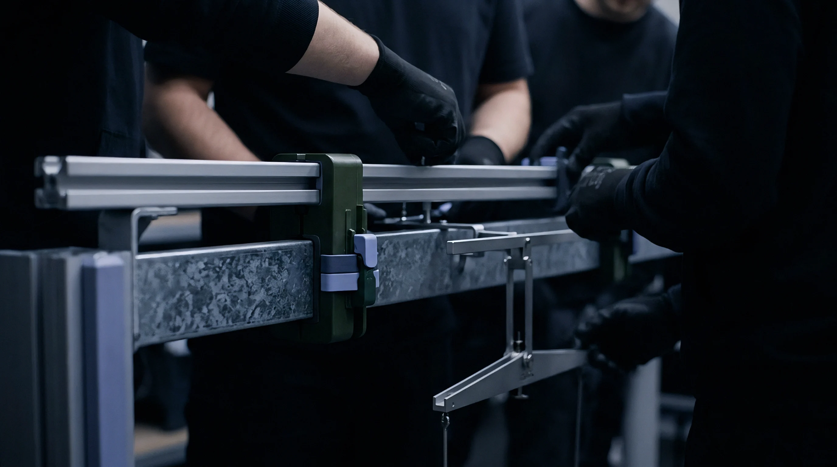
The gap between raw structural concrete and imported machine baseplates determines force transfer efficiency. Precision machinery levelling relies on adjustable steel wedges or jacking screws, leaving gaps ranging from fifty to one hundred fifty millimeters beneath cast iron equipment frames. Pouring high-performance grouting materials fills these voids, establishing complete surface contact across baseplate flanges.
Non-shrink cementitious grouts provide adequate compressive strength for static equipment but deteriorate under high impact frequency. Heavy dynamic equipment demands epoxy resin grouting formulations that feature compressive strengths exceeding one hundred megaspascals, tensile strength over fifteen megaspascals, and superior chemical resistance to cutting fluids and hydraulic oils. Epoxy resins bond tightly to cast iron and cured concrete, creating a monolithic seal against fluid ingress.
Leaving levelling shims under heavy machine baseplates creates concentrated point loads that crack epoxy grout caps during heavy dynamic cyclic strokes.
Thermal expansion mismatches present design challenges when applying epoxy grouts across large surface areas. Epoxy resins possess coefficients of thermal expansion higher than underlying structural concrete, inducing shear stress along concrete grout boundaries during temperature shifts. Pouring epoxy grout in isolated rectangular pads limits continuous pour length, preventing thermal shear cracking along anchor bolt perimeter pockets.
| Physical Property | Standard Cementitious Grout | High-Strength Non-Shrink Cementitious | Three-Component Epoxy Resin Grout |
|---|---|---|---|
| Compressive Strength (28-Day) | 40 to 50 MPa | 60 to 80 MPa | 100 to 120 MPa |
| Tensile Flexural Strength | 3.5 to 5.0 MPa | 6.0 to 8.5 MPa | 18.0 to 25.0 MPa |
| Modulus of Elasticity | 25 to 28 GPa | 30 to 35 GPa | 12 to 16 GPa |
| Linear Shrinkage Rate | 0.05% to 0.10% | 0.00% to 0.02% | 0.00% (Zero Shrinkage) |
| Dynamic Damping Capacity | Low Damping Profile | Moderate Damping Profile | High Damping Capability |
Levelling Wedge Extraction and Load Transfer Arithmetic
Cracks spread quickly.
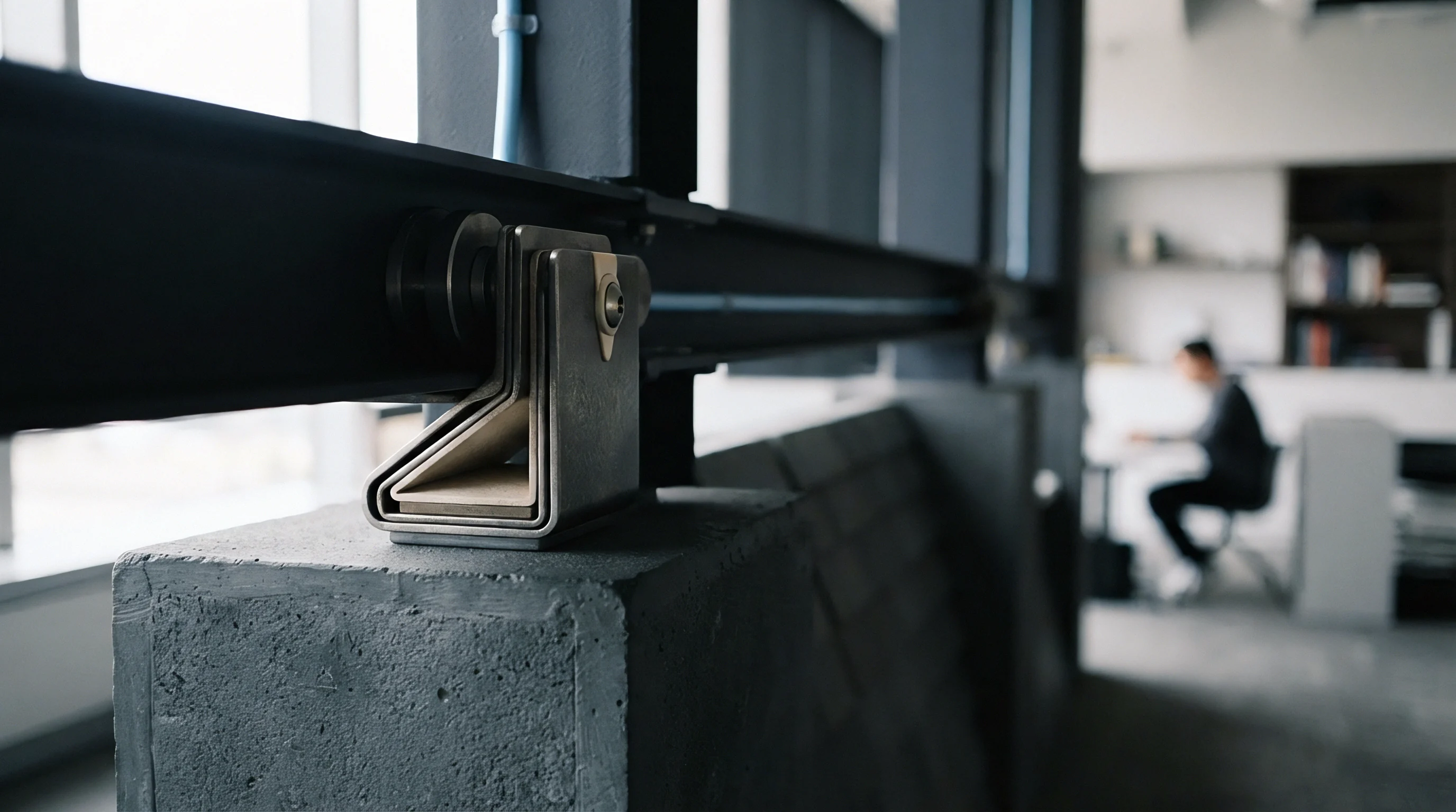
Leaving permanent steel levelling shims or wedges beneath machine baseplates after grouting creates hard contact points, bypassing the grout bed. During continuous machinery operation, dynamic impact forces transfer almost entirely through these isolated steel shims rather than distributing evenly across the grout surface. Localized overstressing fractures grout edges and warps machine baseplates over extended operational runs.
Calculating load distribution beneath machine baseplates clarifies stress concentration risks. Take a one-hundred-twenty-ton imported stamping press baseplate resting on eight levelling points. Total static machine weight equals 1,177 kilonewtons, with dynamic press impact forces contributing an additional dynamic force of 850 kilonewtons, producing a total peak load of 2,027 kilonewtons.
Assume each of the eight grout pad areas measures 400 millimeters by 400 millimeters, giving 0.16 square meters per pad and a total bearing area of 1.28 square meters. The resulting peak bearing stress reaches 1.58 megaspascals across the grout interface.
Standard non-shrink cementitious grout rated for 60 megaspascals static strength easily handles 1.58 megaspascals, but cyclic fatigue rules dictate a maximum allowable working stress of ten percent of ultimate compressive strength under impact conditions (6.0 megaspascals limit). However, if four levelling wedges remain locked in place post-grouting, sixty percent of the total load shifts to those four hard contact points, spiking bearing stress on those isolated pockets to 3.80 megaspascals and exceeding the dynamic shear threshold of standard cementitious materials, causing localized micro-cracking.
Standard operating procedures dictate backing off levelling jacking screws or removing steel adjustment wedges once epoxy grout reaches full compression cure hardness. Removing shims allows machine frame loads to settle evenly across the resilient grout pad, maximizing dynamic vibration attenuation and maintaining bedplate flatness.
The long-term creep rate of heavy resin grouts subjected to hot lubricating oil immersion at seventy degrees Celsius over a ten-year operating life remains an unresolved point among structural engineers.
Interface

Civil Handover Criteria and Cylinder Cure Verification
Time cures concrete.
Handing over civil foundations to machinery installation crews requires rigid document verification and physical field testing. Concrete compressive strength must achieve design targets before applying high torque to anchor bolts or placing multi-ton machinery components on raw concrete decks. Standard mix designs reach twenty-eight-day cure milestones before achieving full structural load capacity, though early-strength concrete additives accelerate scheduling constraints.
Cylindrical concrete test samples cast alongside foundation pours provide verified laboratory crush test data. Structural acceptance mandates average sample compressive strength reaching ninety-five percent of specified design strength prior to equipment placement. Anchor bolt torque application before concrete reaches minimum strength goals crushes internal concrete matrix bonds around embedment plates, causing structural pull-out failure during production surges.
- Concrete Cylinder Test Certificates confirm average compressive strength reaches ninety-five percent of structural design specifications.
- In-Situ Moisture Measurements indicate concrete surface relative humidity falls below seventy-five percent prior to resin application.
- Perimeter Expansion Joint Inspections verify complete isolation break without bridging debris or continuous rebar links.
- Topographical Surface Audits demonstrate pit elevation alignment within three millimeters of mechanical elevation datum.
Surface moisture content across concrete foundation tops dictates epoxy grout bonding success. Relative humidity inside concrete slabs exceeding seventy-five percent prevents epoxy resins from penetrating concrete pores, inducing delamination at grout interfaces under high dynamic shear forces. Applying electrical impedance meters or calcium chloride moisture tests validates concrete dryness before mixing resin compounds.
Isolation Joints and Surrounding Structural Slab Decoupling
Slabs transmit vibration.
Rigid connection between heavy machine inertia blocks and surrounding plant floors transfers low-frequency mechanical energy into building columns and adjacent machinery. Dynamic shock waves propagate through connected floor slabs, disrupting nearby coordinate measuring machines or computer numerical control grinding cells. Perimeter expansion joints isolate foundation inertia blocks from surrounding floor structures.
Isolation joints incorporate closed-cell elastomeric foam boards or high-density cork sheets running the full depth of the concrete inertia block. Joint widths measuring twenty-five to fifty millimeters decouple the heavy foundation block from adjacent floor slabs. Elastomeric joint sealants applied across joint tops prevent coolant, oil, and metal chips from filling isolation gaps and bridging structural separation.
Foundation cure duration follows concrete cylinder test data rather than calendar days on a site schedule.