Injection Mold Qualification Protocol and Tooling Steel Selection Criteria
Tool steel selection and scientific qualification protocols dictate mold life, cycle efficiency, and dimensional capability under continuous production.

Metallurgy
Tool longevity depends on how closely the physical properties of a mold alloy match the chemical and mechanical demands of the resin. The choice of core and cavity steels sets the production lifecycle before components require re-machining or replacement. Glass fibers, flame retardants, and halogenated additives introduce abrasive and corrosive wear that will quickly ruin unprotected surfaces.
When sizing tools for peak injection pressure, engineers balance yield strength, Rockwell C hardness, thermal conductivity, and fracture toughness to prevent cracking or deflection.

Resin Chemistry and Tool Steel Compatibility
Resin formulations determine what cavity surfaces must withstand. Unfilled polyolefins such as polypropylene and polyethylene cause minimal abrasive wear, so high-conductivity aluminum alloys or pre-hardened P20 steel (1.2311) hold up across long production runs. Abrasive glass-filled grades, like 30 percent glass-filled polybutylene terephthalate or polyamide 66, quickly wash out sharp gate details and runner shut-offs.
Cavity inserts for these materials require through-hardened D2 tool steel (1.2379) or powder metallurgy options like CPM 9V to provide the carbide density needed against high-velocity slurry wear.
Corrosive resins present chemical failure modes where raw hardness offers little protection. Polyvinyl chloride releases hydrochloric acid during processing, and fluoropolymers such as polyvinylidene fluoride produce hydrofluoric acid byproducts. Standard carbon steels oxidize under these off-gases, developing micro-pitting across parting lines and cavity faces.
High-chromium stainless steels ~ particularly AISI 420 (1.2083) hardened to 48 to 52 HRC or precipitation-hardened 17-4 PH ~ resist acid attack and maintain surface finish without constant re-polishing.
| Steel Grade | Standard Hardness (HRC) | Thermal Conductivity (W/m·K) | Wear Resistance Mode | Target Resin Compatibility |
|---|---|---|---|---|
| AISI P20 (1.2311) | 28 – 32 | 29.0 | Low Abrasive / Low Corrosive | Unfilled PP, PE, PS, ABS |
| AISI H13 (1.2344) | 46 – 52 | 24.5 | Moderate Abrasive / High Thermal Fatigue | PA6, POM, PC, Polyolefins |
| AISI 420 (1.2083) | 48 – 54 | 19.5 | High Corrosive / Moderate Abrasive | PVC, PVDF, Flame-Retardant Resins |
| AISI S7 (1.2357) | 54 – 58 | 22.5 | High Impact / Shock Resistance | Heavy-Wall Polyolefins, Structural Inserts |
| CPM 9V | 54 – 58 | 20.0 | Severe Abrasive Wear | 30%+ Glass-Filled PA66, PBT, PEEK |
Thermal Conductivity versus Mechanical Hardness Tradeoffs
Heat dissipation within the mold sets the lower limit on cycle time. High-hardness tool steels generally carry lower thermal conductivity because their alloys are loaded with vanadium, molybdenum, and tungsten. When heat builds up in deep core pins or isolated cavity features, hot spots develop, lengthening cooling cycles and causing uneven part shrinkage.
Copper-beryllium alloys (C17200) and copper-nickel-silicon formulations offer conductivity above 100 W/m·K, drawing heat out roughly four times faster than standard H13 steel.
Tool steel with thermal conductivity below 20 W/m K increases cooling cycle time by up to 28 percent when molding unfilled polyolefins.
Placing high-conductivity alloy inserts directly in heat-retaining core zones evens out cooling rates across intricate part geometries. Because soft copper alloys yield under continuous high injection pressure, designers commonly seat copper-beryllium core pins inside hardened H13 retaining plates, pairing rigidity with efficient local heat extraction.
Mismatching the alloy to the resin chemistry accelerates pitting, driving premature tool replacement and unplanned tooling expense.

Geometry
Cavity and core arrangements govern how molten polymer flows under high pressure. Cavity spacing, runner sizing, and cooling line distribution must be balanced to maintain uniform pressure delivery and steady thermal extraction. Abrupt wall thickness steps or undersized gates induce localized shear heating, degrading the melt and causing internal voids.
Tool construction comes down to supporting dynamic hydraulic loads with rigid, properly backed tool plates.

Conformal Cooling Circuit Layout and Heat Transfer
Conventional straight-drilled cooling lines cannot follow the contours of complex parts. Deep cavity pockets and curved walls end up with uneven cooling, leading to molded-in stress, post-mold warp, and longer cycle times. Direct metal laser sintering allows cooling channels to track complex cavity geometries at a consistent distance.
Holding that uniform offset between the fluid channel and the cavity wall removes hot spots and accelerates cooling.
Cooling performance depends on channel flow dynamics. Conformal circuits need smooth transitions to sustain turbulent flow, with Reynolds numbers calculated to stay above 4,000. Dropping below this threshold allows laminar flow to develop an insulating boundary layer along the channel walls, sharply cutting heat transfer efficiency.
Draft Angles and Vent Depth Specifications
Clean part release requires deliberate wall taper. Inadequate draft leads to scuffing, drag marks, and high ejection forces that can punch ejector pins into the part. Polished vertical surfaces require at least 0.5 degrees of draft per side; textured surfaces need an additional 1.0 degree for every 0.025 millimeters of texture depth on the VDI 3400 scale.
Deep ribs and tight pockets require specific draft allowances to avoid pulling a vacuum during mold opening.
- Venting Depth Limits ~ Steel vent channels ground into parting lines permit displaced air to escape during rapid resin injection without allowing polymer melt to form flash.
- Draft Angle Allowance ~ Vertical cavity walls incorporate progressive clearance angles matched to surface texture specifications to reduce mechanical drag during ejection.
- Cooling Pitch Ratio ~ Water lines maintain a pitch distance between two and three times the channel diameter to optimize structural integrity and heat removal.
- Shut-Off Pre-Load ~ Angled core and cavity mating faces feature calculated pre-load dimensions to guarantee positive seals under full machine clamp tonnage.
Vents must exhaust gas quickly to prevent dieseling. Compressing trapped air inside dead-end pockets can spike local temperatures past 600 degrees Celsius, burning the polymer and pitting the tool steel. Flash-free vent depths depend strictly on melt viscosity: crystalline resins such as polyamide require narrow depths between 0.010 and 0.015 millimeters, whereas high-viscosity amorphous resins like polycarbonate tolerate vents up to 0.038 millimeters.
Gate blush and sink defects are often blamed on resin moisture when the root cause is simply an unbalanced runner layout.


Validation
A structured validation protocol takes a new tool from initial sampling to a predictable production process. Establishing repeatable parameters requires staged testing to prove the mold can hold print tolerances across regular production. The qualification workflow isolates resin consistency, machine hydraulics, and mold mechanics to create an audited processing record, using scientific molding data in place of trial-and-error adjustments.

Installation and Operational Phase Execution
Installation Qualification confirms that the press, mold, and auxiliary hookups conform to facility specifications. Before running steel, technicians verify platen parallelism, tie-bar strain calibration, water manifold delta-P, and hot-runner controller stability. Dynamic dry cycling follows, checking that ejector strokes, side-action cams, and core-pull sequences actuate smoothly without binding.
Operational Qualification maps the workable process window for the tool. Work starts with short-shot rheology studies to plot viscosity across injection speeds. Plotting peak hydraulic pressure against injection velocity yields a shear-rate curve, identifying the flat region where material viscosity remains stable despite small speed variations.
- Establish cavity filling speed using a rheology curve to locate the flat region of the viscosity-versus-shear-rate graph.
- Set the transfer position to switch from fill to pack at 95 to 98 percent of total part volume using stroke position sensors.
- Perform a gate seal study by incrementally increasing pack time and measuring part mass until weight stabilizes across three consecutive runs.
- Conduct a hold pressure optimization study, adjusting packing force to eliminate sink marks and internal voids while verifying part weight stability.
- Map the operational window boundaries by adjusting melt temperature and pack pressure to establish the minimum and maximum acceptable limits.

Scientific Molding and Process Window Optimization
Decoupled molding separates mold filling from packing and holding. In a Decoupled II process, velocity control drives the screw to fill 95 percent of the cavity before switching over to pack pressure for the remainder, avoiding hydraulic spikes. Decoupled III uses in-cavity pressure transducers to switch from fill to pack based directly on real-time cavity pressure rather than screw position.
| Qualification Phase | Core Objective | Primary Data Output | Acceptance Gate Criteria |
|---|---|---|---|
| Installation (IQ) | Utility and Machine Verification | Platen parallel alignment log, water flow rate per loop | Zero mechanical interference; flow > 10 L/min per circuit |
| Operational (OQ) | Viscosity and Gate Seal Study | Apparent viscosity curve, part weight vs hold time graph | Viscosity plateau identified; gate seal time verified ±0.2 sec |
| Performance (PQ) | Long-Run Stability Verification | Continuous 8-to-24 hour run production data log | Zero uncontained alarms; process capability Cpk ≥ 1.67 |

How Does Cavity Pressure Decoupling Mitigate Volumetric Shrinkage Variance?
Direct cavity monitoring catches raw material viscosity shifts that screw position sensors miss. If resin viscosity increases between lots, fixed stroke transfer leaves cavities short, causing sink marks and undersized parts. Transducers installed behind ejector pins or in the cavity wall read actual melt pressure and hold packing force until the gate freezes, maintaining uniform volumetric shrinkage across raw material lots.
Compliance with ISO 20457 Clause 5.4 mandates continuous cavity pressure monitoring during qualification trials to invalidate lots produced outside the calibrated pressure threshold.
Comparing hydraulic line pressure to actual cavity pressure highlights flow resistance through the machine nozzle, runner, and gate. High pressure drops point to pinched runners or tight gates, which force the press to run near its hydraulic limits and shrink the viable operating window.
Qualification dossiers built around ISO 20457 Section 6.2 require re-qualifying the tool if peak cavity pressure shifts more than five percent from baseline.


Metrology
Metrology turns sample dimensions into statistical capability data. First Article Inspection Reports measure critical features across all cavities to separate tool machining errors from uneven shrinkage. Analyzing statistical indices confirms whether the tool will reliably hold print dimensions during production runs.

Statistical Process Capability Metrics for Tooling Sign Off
Tooling sign-off depends on Cpk and Ppk indices. Cpk captures potential capability from short-term sample variation under centered conditions, whereas Ppk reflects total variation across long runs, including resin lot differences, ambient factory shifts, and machine thermal drift. High-cavitation molds require individual capability calculations for each cavity to expose mechanical or thermal imbalances.
Take a 32-cavity connector mold with a critical wall dimension specified at 2.000 millimeters ±0.050 millimeters. Running 30 samples per cavity provides the baseline data. If Cavity 12 returns a mean of 2.035 millimeters with a standard deviation of 0.004 millimeters, the upper capability calculates to a Cpk of 1.25.
Although parts fall inside print limits, the cavity misses the 1.67 Cpk threshold required for high-volume release and requires steel adjustment.

Steel Safe Machining Strategy and Modification Loops
Machining steel-safe avoids the need to weld components during sampling adjustments. External features are cut slightly undersized in the cavity, while internal pins and cores are left oversize. Initial parts come out with extra material on critical features.
After measuring initial shrinkage, technicians remove precise amounts of metal to center dimensions within the tolerance band.
Steel safe dimensions on core pins receive mechanical adjustments only after complete thermal stabilization during high-cavitation production runs.
Fine-tuning steel-safe geometry with electrical discharge machining or precision grinding removes the metallurgical risks of micro-TIG or laser welding. Core pin diameters can be brought down to achieve exact hole sizes without compromising original heat-treat properties.
Core pins remain slightly oversized until the mold achieves true thermal equilibrium under production conditions.

Wear
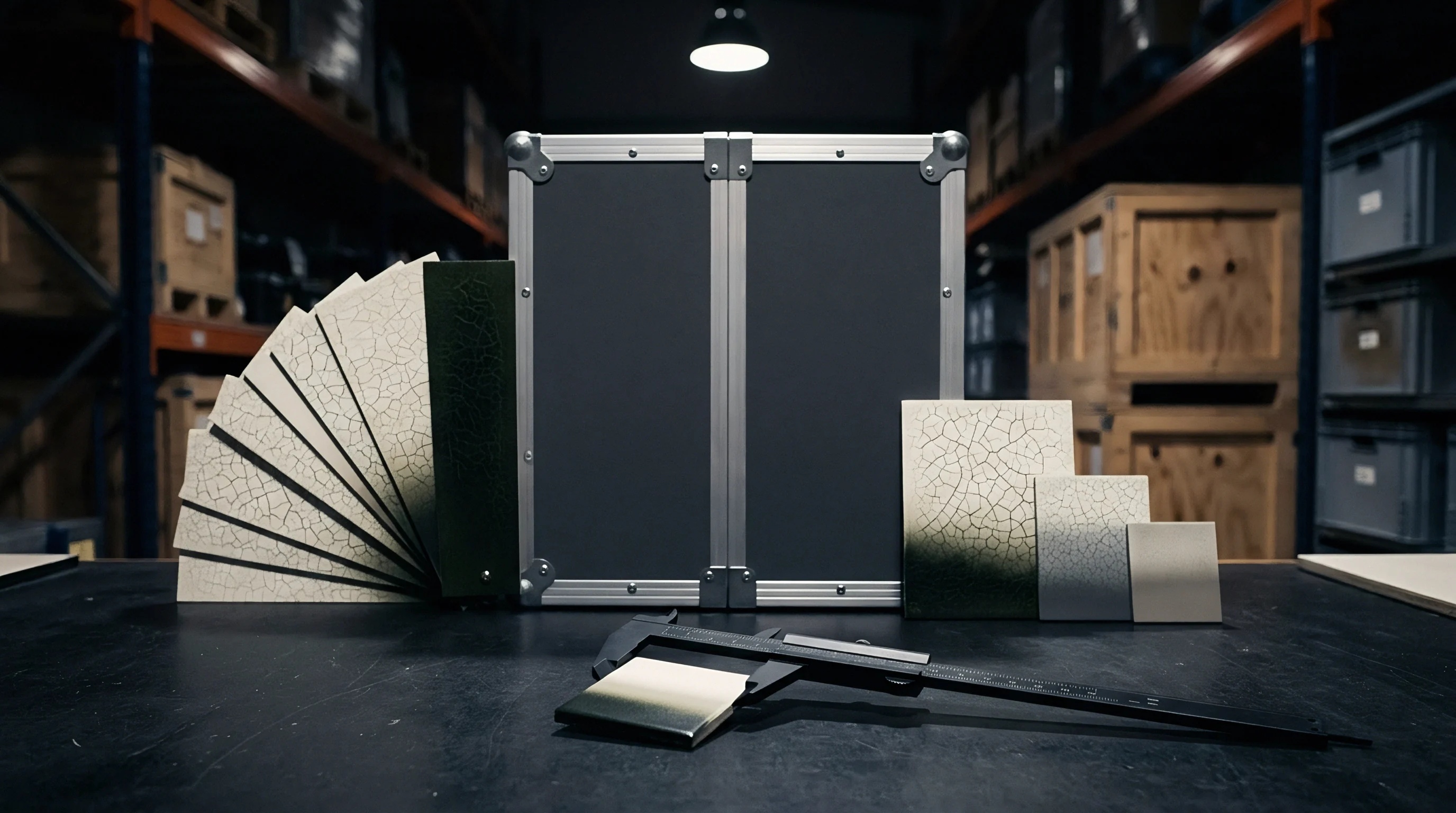
High-velocity resin flow gradually erodes tool surfaces over time. Wear starts as subtle surface polishing and progresses to micro-pitting, galling, and parting line wash-out. Setting clear inspection criteria catches wear patterns before parts flash or drift out of tolerance.
Surface Treatments and Thin Film Coatings
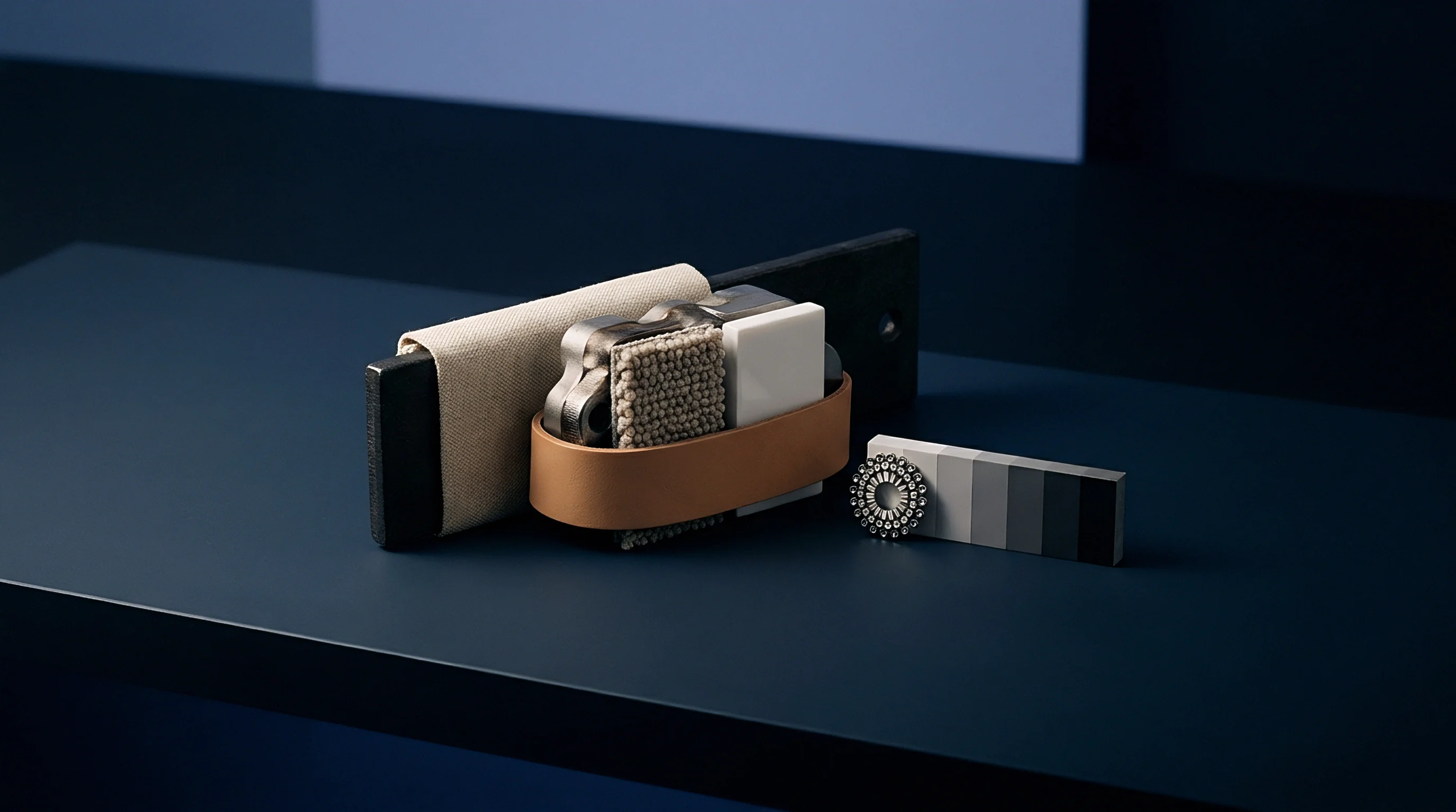
Thin-film surface treatments raise hardness and adjust surface energy without altering finished dimensions. Physical Vapor Deposition applies micro-thin ceramic layers ~ such as Titanium Nitride, Chromium Nitride, or Diamond-Like Carbon ~ below the steel tempering temperature, protecting base hardness. These coatings boost surface hardness beyond 2,000 Vickers to resist glass-fiber abrasion.
Electroless nickel plating co-deposited with polytetrafluoroethylene delivers chemical protection and lowers friction on moving slides. The reduced friction allows slides to run smoothly without liquid lubricants that might contaminate cleanroom parts.
| Degradation Mechanism | Root Cause Driver | Surface Countermeasure | Quantitative Inspection Threshold |
|---|---|---|---|
| Abrasive Gate Erosion | High-velocity glass-fiber filler impact | PVD Titanium Nitride (TiN) Coating | Gate dimension opening > 0.05 mm from print |
| Parting Line Indentation | Excessive machine clamp tonnage | Local Laser Surface Hardening | Part flash height exceeding 0.03 mm |
| Slide Action Galling | Unlubricated metal-to-metal friction | Diamond-Like Carbon (DLC) Coating | Scuff marks visible; drag force spikes > 15% |
| Cavity Surface Pitting | Corrosive polymer gas condensation | Electroless Nickel Plating | Surface roughness Ra exceeding 0.2 µm |
Preventive Maintenance Metrics and Degradation Triggers
Cycle counts establish preventive maintenance intervals. High-speed molding cycles create mechanical fatigue across return pins, alignment locks, and ejector plates. Preventive maintenance programs schedule tool teardowns at fixed shot counts rather than waiting for component failure on press.
- Galling on Sliding Cores ~ Dry sliding contact strips protective oxide layers, forcing raw steel surfaces to cold-weld under mechanical clamping loads.
- Cavitation Erosion ~ Rapid implosion of trapped gas bubbles near gate land areas pits cavity steel through repetitive hydraulic shockwaves.
- Thermal Fatigue Micro-Cracking ~ Cyclic heat loading from high-temperature engineering polymers induces surface stress cracks along un-cooled core regions.
- Parting Line Flash Micro-Deformation ~ Repeated clamping forces beyond yield strength sink steel parting edges, creating clearance gaps where melt flows freely.
Parting line flashes exceeding fifty micrometers indicate localized mold clamp deflection or micro-indentation of cavity edges.
Mating dissimilar metals, such as bronze wear plates against hardened H13 steel, prevents adhesive galling along high-speed slide actions.
Whether nano-structured physical vapor deposition coatings can extend core pin life under sustained glass-fiber erosion without altering critical heat transfer rates remains unproven across extended production cycles.

Handoff
Transferring tooling from the mold builder to the commercial production plant requires clear technical and physical sign-offs. Structured handoff protocols protect tooling investments by aligning mechanical drawings, spare parts inventory, and verified process baselines so plant engineers receive production-ready assets.

Commercial Transfer Dossier and Tooling Asset Sign Off
A complete tooling transfer package contains mechanical drawings, hot-runner wiring schematics, steel certifications, and maintenance assembly instructions. The final 3D CAD files must reflect all steel-safe adjustments made during metrology tuning; missing updates between physical steel and CAD models complicate future replacement inserts and extend repair downtime.
The receiving plant reviews baseline in-cavity pressure profiles, thermal imaging data, and water circuit delta-P records from the mold builder. Comparing production commissioning data against original factory acceptance records confirms the tool arrived and runs without hidden damage.

Spare Parts Package and Production Readiness Gating
High-cavitation tooling requires a dedicated spare parts package to prevent downtime. Spare quantities are calculated from component wear observed during qualification runs. Long-lead items ~ including custom core pins, cavity inserts, internal hot-runner tips, and gate bushings ~ must accompany the mold shipment.
- Verify that the physical mold weight, dimensions, and lifting eye locations match the commercial specification sheet and crane capacity limits.
- Audit the technical documentation package to confirm inclusion of signed First Article Inspection Reports and final approved 3D CAD files.
- Inspect the spare parts package, verifying that all core pins, ejector pins, and hot-runner heating elements match drawing rev levels.
- Mount the mold into the target production machine to run a mandatory four-hour operational verification dry-cycle trial.
- Execute a 500-shot continuous production run, comparing part weights and dimensions against baseline qualification data.
Completing these physical verification gates confirms the mold is ready for full commercial production.