Finite Element Virtual Unclamping Formulation for Anisotropic Polymer Moldings
Virtual unclamping maps fixture-constrained inspection scans to free-state polymer geometry through anisotropic stiffness tensors and structural springback calculations.


Anisotropy
Fiber Orientation Mapping and Micro Mechanics Homogenization
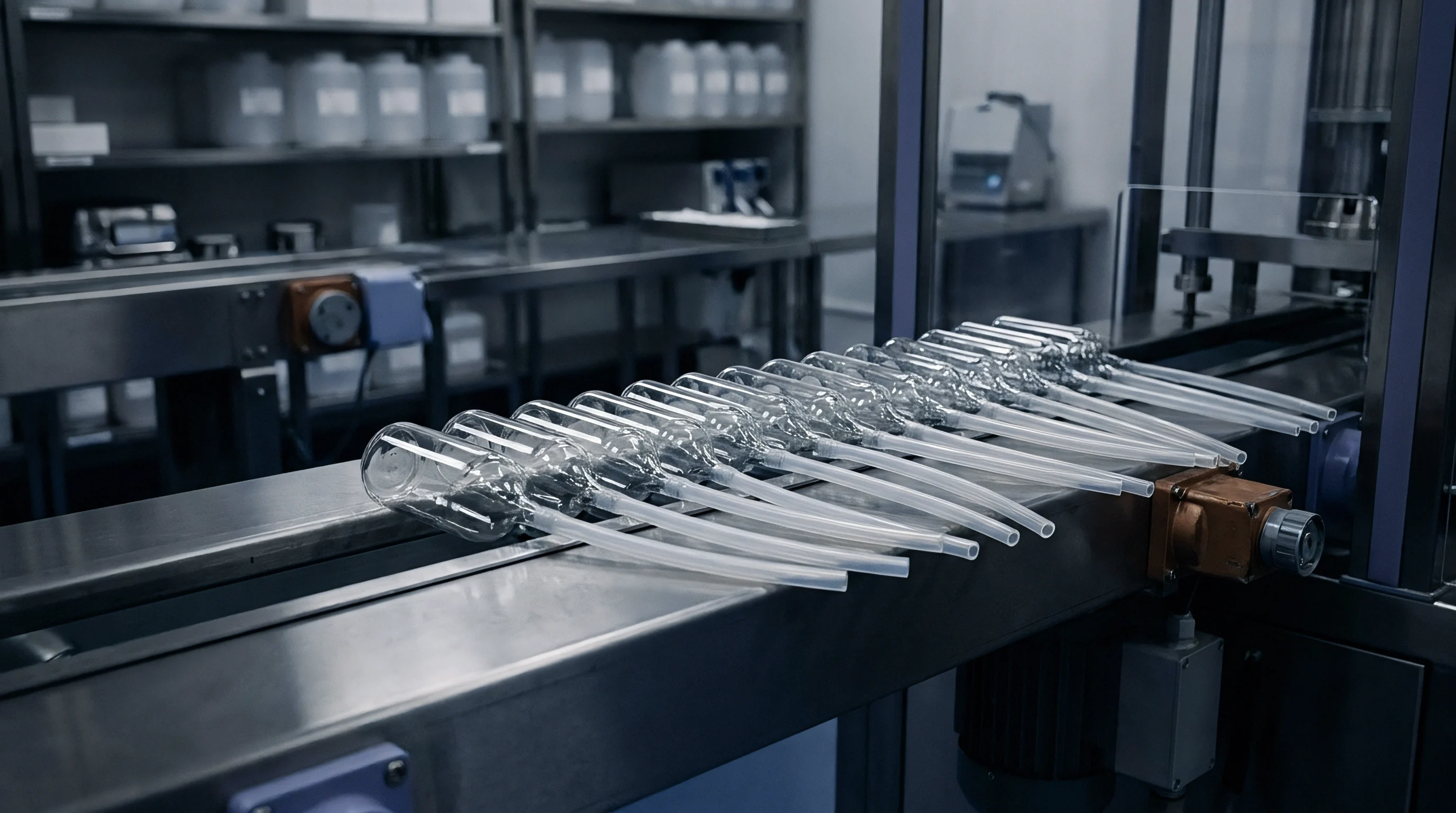
Local polymer melt shear during injection causes the mechanical properties of short-fiber-reinforced thermoplastics to vary throughout a part. Numerical mold-filling simulations output second-order orientation tensors at every finite element integration point, capturing how glass or carbon fibers align through the shell and core layers across the wall thickness. Because this alignment drives local stiffness variations, the resulting orthotropic stiffness matrix must undergo explicit micromechanical homogenization before structural stress analysis.
Analytical models like Mori-Tanaka and Tandon-Weng bridge microscopic fiber-matrix phase properties and macroscopic continuum mechanics. Calculating the local stiffness matrix requires the resin’s elastic modulus and Poisson’s ratio, fiber aspect ratio, and local orientation components. Bypassing fiber tensor interpolation causes structural solvers to default to isotropic averages ~ an oversight that can introduce springback displacement errors exceeding forty percent once the part leaves its fixture.
- Flow Simulation Data Export transfers mid-plane or three-dimensional mesh fiber orientation tensors in standard neutral format from injection molding software to the structural pre-processor.
- Constitutive Material Mapping maps orientation tensor fields onto the mechanical stress mesh using nearest-neighbor or spatial kriging algorithms to avoid element-edge interpolation artifacts.
- Phase Property Homogenization calculates six-by-six orthotropic elasticity tensors at every element centroid using phase volume fractions and aspect ratios derived from burn-off tests.
- Thermal Expansion Tensor Assembly computes directional thermal expansion coefficients along principal orientation axes to set initial conditions for residual stress.
Matrix shrinkage remains directional because aligned glass filaments constrain the polymer. Parallel to flow, thermal contraction is muted as rigid fibers absorb the compressive thermal load. Transverse to the flow vector, linear thermal shrinkage increases by factors ranging from three to six, depending on resin crystalline content and filler loading percentages.
| Polymer Compound Grade | Filler Fraction by Weight | Parallel Elastic Modulus | Transverse Elastic Modulus | Flow Direction Expansion Coefficient | Cross Flow Expansion Coefficient |
|---|---|---|---|---|---|
| PBT Glass Reinforced 30 Percent | 30% Short Glass | 9.8 GPa | 4.2 GPa | 22 x 10^-6 /K | 78 x 10^-6 /K |
| PA66 Glass Reinforced 30 Percent | 30% Short Glass | 10.5 GPa | 4.8 GPa | 19 x 10^-6 /K | 82 x 10^-6 /K |
| PPS Glass Reinforced 40 Percent | 40% Structural Glass | 14.2 GPa | 6.1 GPa | 14 x 10^-6 /K | 54 x 10^-6 /K |

Viscoelastic Residual Stress Accumulation
Thermal gradients across thin molded walls cause non-uniform cooling inside the closed cavity. Polymer molecules solidify under high packing pressure near the gate, while outer surfaces freeze rapidly against chilled core and cavity steel. This thermal history creates an internal stress profile characterized by compressive stresses along outer skins and tensile stresses within core regions.
Fiber alignment distributions across thin molded walls dictate differential thermal strain vectors prior to clamp release.
Viscoelastic stress relaxation continues as the molding cools from ejection temperature down to ambient conditions. Simple elastic springback models assume instantaneous stress release, ignoring time-dependent response, but polymer chains creep and age during storage before dimensional measurement. Omitting Williams-Landel-Ferry shift functions or time-temperature superposition leads to miscalculated long-term warpage in thin-walled housings.
Standard quality checks reveal dimensional drift when parts spend twenty-four hours in temperature-controlled holding bays before coordinate measuring machine verification, resulting in false rejection of tooling dimensions.

Kinematics

Boundary Condition Transformation and Reaction Force Release
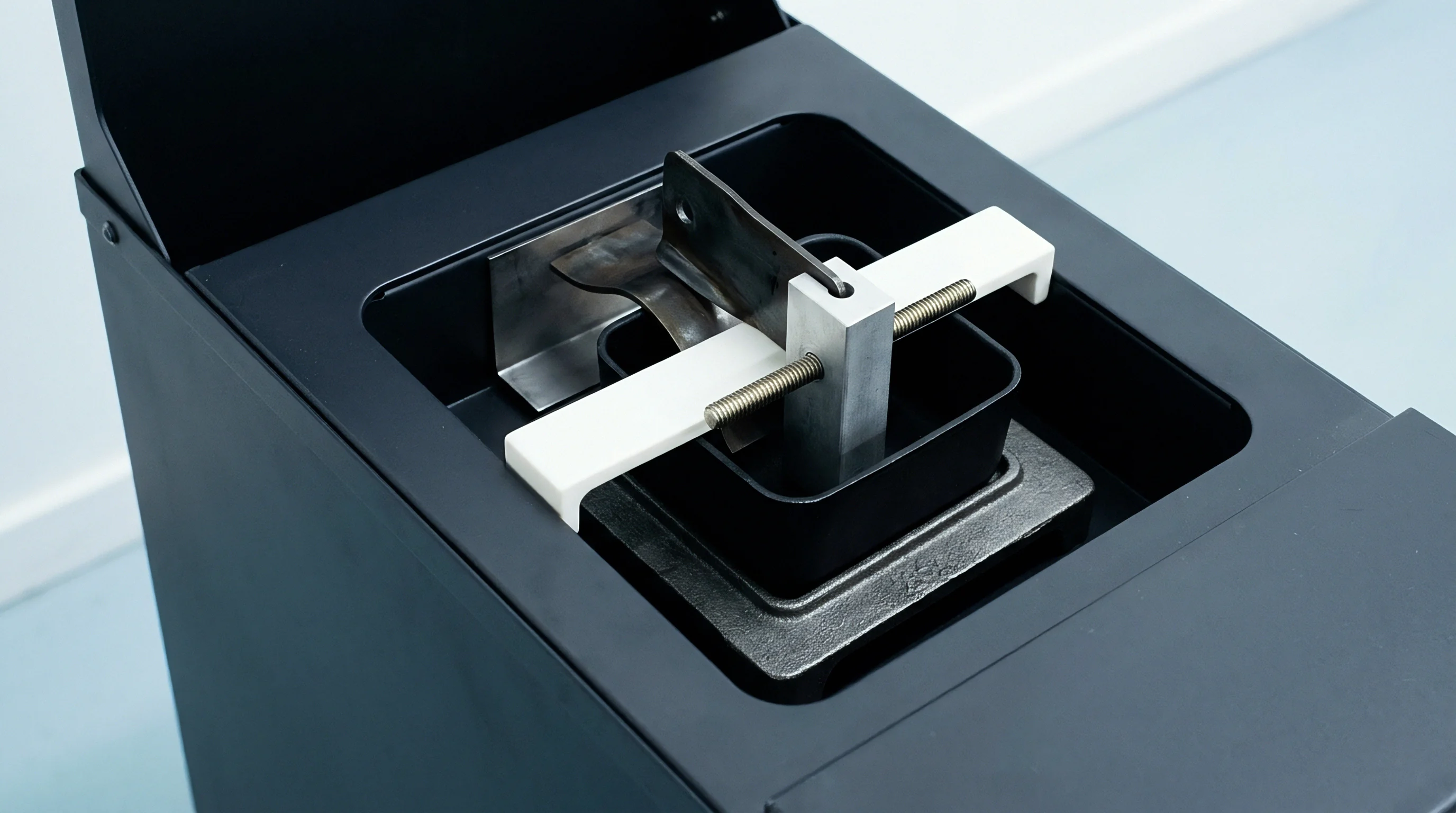
Physical inspection fixtures lock flexible moldings using datum pads, pin locators, and toggle clamps to simulate final assembly conditions. Virtual unclamping formulations reverse this process numerically by converting fixture-induced displacement constraints into equivalent internal reaction forces. The structural solver records nodal reaction vectors existing at clamped boundary points while holding the part in its nominal inspection position.
Formulating the virtual release step involves removing Dirichlet boundary conditions at fixture points while applying equal and opposite force vectors to the matrix equation. The global stiffness matrix undergoes inversion or decomposition to compute free-state node displacements. Linear static solvers assume infinitesimal strain theory, treating the stiffness matrix as a constant operator throughout unclamping.
When part flexure exceeds wall thickness, however, linear assumptions fail to account for stress stiffening and membrane strain conversion across curved panel surfaces.
Virtual clamp removal formulations that ignore shear coupling miscalculate springback direction across curved ribs.
- Over-constrained Datum Lockouts occur when simulation setups apply fixed zero-displacement boundary conditions to secondary locators that physically slide along slot bushings in production tooling.
- Rigid Body Motion Divergence arises during complete boundary condition removal without establishing non-influential six-point mathematical constraints to anchor the free-floating component in spatial coordinates.
- Frictional Contact Locking happens when numerical models ignore friction coefficients at locator contact faces, generating artificial force spikes that hold phantom bending moments in the part frame.
- Contact Normal Misalignment surfaces when FEA locator points align with nominal CAD geometry rather than actual optical scan surface normals.
Co Rotational Formulations for Large Springback Displacements
When unclamped from inspection frames, thin polymer moldings undergo significant geometrical rotations while experiencing minimal local strains. Co-rotational shell formulations separate rigid body motion from pure deformational strain at every element level. A local coordinate frame rotates continuously with element nodes during each load step, maintaining linear strain-displacement relations locally while non-linear geometric matrices manage global spatial translations.
Updated Lagrangian algorithms update global mesh coordinates at every calculation increment, modifying stiffness matrices to reflect instantaneous geometry changes. Polymer moldings reinforced with anisotropic fibers display strong coupling between flexural bending and in-plane shear. When large springback displacements occur, ignoring secondary geometric stiffening undercalculates outward deflection along unreinforced edge flanging.
Executing tooling modifications based on linear virtual unclamping predictions often forces multiple recuts of core and cavity steel to meet tight drawing tolerances, adding weeks to tool qualification schedules.
Dimensional shifts in fixture discrepancies are frequently attributed to material batch variations rather than improper kinematic constraint removal within the CAD extraction tool.


Grid

Mesh Topology and Sensor Point Spatial Alignment
Physical coordinate measuring machine probes generate discrete point clusters across clamped part surfaces, while optical white-light or blue-light surface scanners capture dense high-resolution point clouds representing the entire exterior shell geometry. Aligning measured physical scan points with finite element mesh nodes demands robust spatial interpolation algorithms.
Direct node-to-point matching rarely succeeds because finite element discretizations optimize element aspect ratios, whereas optical scan meshes follow surface feature optical reflectance patterns. Tri-linear isoparametric mapping projects physical surface coordinates onto element face domains, calculating shape function weights to distribute displacement vectors without introducing spatial aliasing. Discrepancies between scan density and simulation grid sizes introduce high-frequency numerical noise into calculated curvature gradients.
- Import raw optical scan point clouds into the spatial alignment workspace and eliminate outlier ambient reflection artifacts.
- Perform a preliminary best-fit alignment between physical scan cloud density and nominal CAD surface geometries using iterative closest point math.
- Project physical scan points along local normal vectors onto the exterior surface faces of the finite element shell structure.
- Construct a spatial displacement vector field representing physical deviations between nominal CAD faces and measured clamped geometry.
- Interpolate displacement vector values onto structural finite element mesh nodes using inverse distance weighting functions.

How Does Mesh Refinement Affect Unclamping Strain Calculations?
Finite element grid density dictates the numerical resolution of local strain gradients generated during clamp release sequences. Coarse shell elements average internal anisotropic stress fields across broad surface areas, artificially softening the localized structural response around rib intersections and sharp corner radii. Element formulation choice directly impacts structural stiffness: standard first-order quadrilateral elements suffer from transverse shear locking when modeling thin flexural components under multi-axis bending loads.
Second-order shell elements with reduced integration points prevent shear locking while accurately capturing displacement gradients across curved automotive panels. Grid convergence studies confirm that element edge lengths near boundary constraint locations must remain below twice the nominal wall thickness to avoid numerical stress singularity errors during stiffness matrix operations.
Focusing mesh refinement solely on high-curvature fillets provides reliable displacement calculations while keeping computational load within reasonable bounds for daily manufacturing quality checks.


Arithmetic

Mathematical Formulation of the Inverse Stiffness System
Governing equations for virtual unclamping build upon incremental equilibrium equations modified by penalty matrices or Lagrange multiplier operators. Let the global structural system equation in the clamped reference frame be written as:
K(u) u = F_ext + R_clamp
Here, K(u) represents the displacement-dependent non-linear global stiffness matrix incorporating anisotropic elasticity tensors derived from fiber mapping. Vector u carries nodal displacements, F_ext contains applied environmental or gravitational loads, and R_clamp contains unknown constraint reaction forces holding the component against locator pins.
During physical coordinate inspection, the displacement vector u_clamped is measured across surface grid points, while Dirichlet constraints fix degrees of freedom at clamping nodes. The numerical formulation solves for reaction vectors R_clamp through inverse extraction:
R_clamp = K(u_clamped) u_clamped – F_ext
Virtual unclamping then computes the unknown free-state equilibrium displacement vector u_free by applying the negative reaction force vector –R_clamp to the unconstrained system:
K(u_free) u_free = F_ext – R_clamp
Because material stiffness K evolves with local geometric rotation and stress-state changes, Newton-Raphson iteration drives residual equilibrium forces below predefined convergence thresholds. The global energy balance must balance internal elastic strain energy against external work performed by boundary reaction releases throughout incremental step sequences.
ISO 10579 free-state drawing annotations without specified clamping force limits result in rejected Quality Assurance dossiers during production ramp-up.
| Formulation Type | Iterative Convergence Method | Geometric Non-Linearity Handling | Mean Wall Computation Time | Peak Displacement Deviation |
|---|---|---|---|---|
| Linear Static Inverse Stiffness | Direct Sparse Matrix Solver | Small Displacement Assumption | 12 Seconds | 0.84 mm (Undercalculated) |
| Updated Lagrangian Shell | Full Newton-Raphson Iteration | Incremental Coordinate Matrix Update | 185 Seconds | 0.04 mm (Baseline Ground Truth) |
| Co-Rotational Shell Formulation | Modified Newton-Raphson Matrix | Local Frame Transformation | 64 Seconds | 0.06 mm (Acceptable Production Speed) |

Numerical Convergence and Penalty Matrix Conditioning
Non-linear equilibrium iterations encounter convergence bottlenecks when stiffness matrix conditioning numbers degrade under high anisotropic modulus ratios. Glass-filled polymers exhibit stiffness ratios exceeding three to one between parallel and perpendicular fiber alignment axes, causing matrix conditioning numbers to skyrocket and leading to ill-conditioned linear solver steps during full clamp releases.
Penalty stiffness values added at constraint points maintain numerical stability during partial boundary releases. However, setting penalty stiffness values too high causes round-off error accumulation in double-precision floating-point arithmetic operations, while setting penalty stiffness values too low permits unphysical boundary penetration, distorting springback calculation output vectors.
- Stiffness Ratio Verification confirms that local orthotropic stiffness matrix terms remain positive definite across all anisotropic material integration points.
- Residual Energy Monitoring tracks force residual norms to confirm convergence stays below one-thousandth of maximum reaction force magnitudes.
- Spurious Mode Suppression applies hourglass control stiffness parameters to reduced-integration shell elements during large rotation load steps.
- Symmetry Tensor Checking verifies that mapped elasticity matrices retain mathematical symmetry prior to structural solver assembly steps.
Whether viscoelastic stress relaxation should be solved concurrently with large-displacement geometric releases or handled as an uncoupled sequential material offset remains a point of technical disagreement among simulation specialists.

Bench

Validation Procedures and Optical Surface Verification
Physical verification of virtual unclamping numerical results requires comparing calculated free-state geometries against real unconstrained optical scan measurements. Experimental setups support the polymer molding on low-density closed-cell foam beds or soft suspension strings to minimize gravitational sag during free-state optical scanning, establishing an unconstrained physical baseline.
Comparison metrics compute point-to-surface vector distances across two million spatial data points. Deviation heat maps highlight localized springback zones along unsupported flanging and large flat panel spans. Virtual unclamping predictions matching physical unconstrained scans within a two-tenth millimeter envelope validate structural stiffness tensors and boundary force calculations for complex structural moldings.
Optical surface scanning at two million points per panel yields a two-tenth millimeter deformation deviation when temperature drifts past two degrees Celsius.
Measurement uncertainty analysis must separate optical scanner point capture errors from numerical interpolation approximations. Ambient temperature drift inside inspection rooms alters polymer part dimensions rapidly due to high thermal expansion coefficients. A temperature shift of two degrees Celsius alters a meter-long polymer molding dimension by over one-tenth of a millimeter, completely masking finite element calculation errors if thermal regulation fails during benchmarking.
| Inspection Methodology | Part Restraint Condition | Percent Gauge R and R Contribution | Dimensional Variance Spread | Cycle Time Per Part |
|---|---|---|---|---|
| Touch-Probe CMM Inspection | Heavy Mechanical Toggle Fixture | 4.2% (Acceptable) | 0.03 mm | 14 Minutes |
| Free-State Optical Scanning | Soft Foam Gravity Support Bed | 18.6% (Marginal) | 0.38 mm | 6 Minutes |
| Virtual Unclamping FEA Pipeline | Fixtured Optical Scan + Numerical Release | 6.8% (Acceptable) | 0.07 mm | 3 Minutes |

Gauge Repeatability and Error Propagation
Integrating numerical simulation steps directly into production quality control workflows introduces virtual gauge repeatability variables. Operator variations occur during manual clamp lever toggling, altering localized surface contact points on physical inspection fixtures. FEA input vectors shift accordingly, generating variable free-state predictions from identical physical parts.
Automated pneumatic clamping fixtures eliminate operator force variability by regulating clamping pressure to specified limits. Virtual unclamping software scripts process fixture sensor output, applying exact measured constraint loads directly to individual boundary nodes within the FEA model solver stream.
A rigorous inspection routine combines physical contact pressure sensors with automated FEA virtual unclamping runs to deliver repeatable free-state dimensional compliance metrics within fast production cycle times.

Contract

Standardized Geometrical Tolerancing and Free State Callouts
Engineering drawings specify part geometries using standardized geometric dimensioning and tolerancing conventions defined under ISO 10579 and ASME Y14.5 standards. Free-state symbols, designated by a letter F inside a circle modifier, indicate that specified geometric tolerances apply when the component experiences no external boundary constraints.
Drawing callouts must explicitly declare maximum allowable clamping forces permitted during fixtured inspection checks. When drawings specify fixtured inspection conditions, virtual unclamping formulations provide the legal verification bridge enabling suppliers to certify unconstrained part dimensions prior to final shipment. Disagreements between component molders and original equipment manufacturers surface when incoming quality inspections measure parts in free-state conditions while manufacturing tooling was validated against constrained fixture gauges.
Contractual acceptance criteria mandate that virtual unclamping simulation files, material mapping logs, and fiber orientation tensor datasets be included directly within the Production Part Approval Process submission dossier submitted to client engineering teams.

Commercial Risk Allocation and Tooling Modification Stage Gates
Modifying injection molding steel tooling to correct warpage errors costs thousands of dollars per iteration and adds project delay penalties to commercial contracts. Determining financial responsibility for tool recuts relies on proving whether dimensional non-conformance stems from improper tool steel cavity dimensions or incorrect processing parameters during molding operations.
Virtual unclamping simulation records serve as objective engineering evidence in commercial disputes over tooling sign-offs. When simulation predictions confirm that part warpage falls within predicted fiber orientation springback bands established during initial mold filling sign-offs, responsibility for tool modifications shifts to the purchasing party who approved nominal cavity geometry. Establishing unambiguous stage-gate sign-offs prior to steel cutting protects molding suppliers from bearing costs associated with late product design alterations.
Under ISO 10579 section 5.2, drawing notes stating free-state variation tolerances without identifying specified fixture restraint forces transfer all dimensional springback compliance risk directly onto the parts molder, nullifying supplier warranty claims once tool steel is hardened.