Establishing Initial Surface Flatness Baselines for Industrial Slabs
Establishing initial slab surface flatness baselines within 72 hours isolates concrete finishing defects from long-term curing deflections and curling.
Datum
Primary surface reference points establish the absolute vertical coordinate frame used to evaluate slab deflection in all subsequent floor tolerance measurements. Industrial ground slabs operating under high-bay racking or narrow-aisle automated material handling equipment require vertical baseline calibrations tied directly to fixed structural elements. Setting vertical control early keeps building movement, moisture-driven subgrade expansion, and post-tensioning adjustments from corrupting raw elevation surveys.
Surveyors initiate this benchmark sequence before concrete placement begins, anchoring coordinate points to structural columns set deep within foundation footings rather than relying on shallow soil grade.
Elevation drift invalidates baseline records whenever structural movement shifts local benchmark coordinates. Perimeter columns serve as the primary monuments. Establishing surface baselines with temporary benchmarks set on unreinforced mud slabs or adjacent unbonded aprons introduces systemic error through ground settlement.
Soil moisture fluctuations during construction can shift unanchored grade stakes vertically by three to five millimeters across forty-eight hours. Benchmarks set on load-bearing column bases embedded below the subgrade friction plane eliminate shallow soil movement risks. Establishing dual control points on opposing building grid lines enables cross-sighting verification, ensuring localized column settlement does not bias broad floor flatness calculations.

Geodetic Control Points and Fixed Site Benchmarks
Setting permanent elevation monuments along perimeter structural columns provides a stable vertical baseline isolated from early subgrade movement. Primary benchmarks consist of stainless steel pins driven into column webs or welded directly to embed plates before slab casting. These pins serve as absolute zero elevations for all subsequent floor measurements.
Primary control network design demands sightline clearance across the entire slab footprint to prevent equipment obstructions from interrupting long-distance optical leveling runs.
Topographic surveys across raw floor placements must reference these fixed monuments through closed-loop differential leveling. Closed loops require the optical operator to sight forward to a temporary point, advance the instrument, and sight back to the preceding position, concluding the loop on the originating benchmark. The closure error resulting from this loop calculation determines whether survey precision satisfies industrial floor audit criteria.
Any closing error exceeding 0.5 millimeters across a fifty-meter traverse invalidates the elevation dataset, forcing a complete re-survey of the pour zone.
| Control Network Rank | Monument Type | Maximum Loop Closure Error | Targeted Floor Application |
|---|---|---|---|
| Primary Network | Structural Column Web Embed Pins | 0.3 mm per 100 m traverse | VNA Turret Truck High-Bay Warehouses |
| Secondary Control | Deep Foundation Anchor Studs | 0.8 mm per 100 m traverse | Standard Automated Guided Vehicle Storage |
| Tertiary Benchmarks | Perimeter Concrete Stem Wall Marks | 1.5 mm per 100 m traverse | Bulk Storage and Wide-Aisle Warehousing |
| Closure tolerances calculated under static ambient thermal conditions in enclosed structures according to ISO 17123-2 precision standards. | |||
Optical Leveling Instruments and Digital Barcode Staffs
Precision spirit levels paired with invar staffs achieve standard deviations below 0.2 millimeters per kilometer of double-run leveling. Invar ~ an iron-nickel alloy possessing an extremely low coefficient of thermal expansion ~ prevents rod length variation during surveys under direct sunlight or space heating. Digital auto-levels reduce operator sighting error by optically processing barcoded graduations along the invar staff, logging precise vertical distances electronically to eliminate reading transcription mistakes.
Setup parameters for digital levels require strict distance balancing between backward and forward sightings. Equidistant sight lengths automatically cancel instrument sightline curvature errors and atmospheric refraction effects. Survey crews keep the optical level within thirty meters of target staffs to suppress atmospheric shimmer created by curing concrete heat hydration.
Evaluating baseline elevation records across new distribution centers requires separating concrete placement errors from structural deflection caused by post-tensioning or subgrade settlement by cross-referencing staff readings against column monuments.
Establishing coordinate grids across floor pours involves setting grid intersections at three-meter or six-meter intervals across both horizontal axes. Marking these grid nodes with temporary non-staining ink before measurement enables repetitive profiling across identical surface coordinates as the concrete cures. Baseline elevation profiles captured at these exact grid nodes serve as the primary evidence when auditing slab settlement or curling behavior over time.
Incorrect vertical benchmarks corrupt every downstream profile calculation. They generate false non-compliance verdicts that trigger expensive, unneeded grinding or conceal severe slab finishing defects that destroy automated material handling equipment speed and operational reliability.

Index
Statistical floor flatness metrics standardise how engineers quantify local bumpiness and overall slab inclination across vast industrial footprints. Developed to replace the obsolete straightedge gap measurement method, the F-number system split floor surface quality into two distinct mathematical components. Flatness, designated as FF, evaluates surface curvature over small distances, reflecting how smoothly a vehicle moves across the slab.
Levelness, designated as FL, measures total floor pitch and slope over longer distances, governing whether tall storage racks lean away from absolute vertical alignment.
Local curvature governs vehicle vibration, and composite values can easily mask localized dips. Floor specifications set distinct target values for overall pour areas alongside strict lower limits for individual pour sections. A slab achieving an overall composite FF 50 rating can still harbour isolated strips with FF 15 ratings, creating localized bumps that rock fork trucks, damage mast assemblies, and spill palletized inventory.
Baseline surveys must separate section results from composite averages to identify structural finishing flaws before contractor handoff.

ASTM E1155 Methodology and Statistical Distribution Parameters
Flatness readings rely on point-to-point elevation differences taken at regular three-hundred-millimeter intervals along specified run lines. The ASTM E1155 standard defines the precise statistical protocol for collecting, filtering, and processing these elevation differences to compute FF and FL values. Survey lines run at forty-five-degree angles to construction joints or layout grids, preventing survey paths from running parallel inside machine-screeded trough lines that mask periodic finishing waves.
Data collection rules mandate a minimum total length of sample lines based on slab surface area. For a floor section exceeding one thousand square meters, the standard calculates minimum survey line length through empirical formulas tied to total floor area. Individual sample lines must contain a minimum of thirty elevation readings, equivalent to a nine-meter linear run.
Short measurement lines fail to establish an adequate sample size, introducing elevated statistical noise that invalidates calculated F-numbers.

Dissecting Flatness and Levelness Mathematical Formulations
Calculations process sequential pitch changes over a three-meter chord length to establish local curvature variations independent of slab tilt. The mathematical engine calculates the difference between adjacent elevation readings taken three hundred millimeters apart. Let yi represent the absolute vertical elevation measured at point i.
The first difference, di, represents the slope over a three-hundred-millimeter segment:
di = yi – yi-1
To isolate local curvature, the formula calculates the difference between consecutive slope values separated by three meters (ten sampling intervals). This difference, designated qi, measures local surface curvature:
qi = di – di-10 = (yi – yi-1) – (yi-10 – yi-11)
The standard deviation of all sample curvature values qi across a survey run determines the statistical flatness value FF. Lower standard deviation indicates a smooth, highly flat surface, yielding a high numerical FF score. The exact equation converting sample variance Sq2 into the final FF score uses an inverse linear relationship:
FF = frac115.843 · Sq
Where Sq represents the sample standard deviation of qi values in millimeters. Levelness FL calculations follow a similar structure but analyze elevation differences across three-meter sample lengths directly, evaluating global tilt rather than micro-curvature. The elevation change zi across three meters is given by:
zi = yi – yi-10
The standard deviation of zi values, denoted Sz, converts into the levelness index FL via the standard empirical formula:
FL = frac115.843 · Sz

Worked Calculation of Combined Composite Values
Combining individual run statistical variances requires weighting each sample by the total linear distance surveyed across the pour section. Consider a newly cast warehouse pour split into three distinct profile runs to establish baseline compliance. Run 1 spans 15 meters yielding 50 readings with an Sq of 0.85 mm.
Run 2 spans 18 meters yielding 60 readings with an Sq of 0.62 mm. Run 3 spans 21 meters yielding 70 readings with an Sq of 1.10 mm.
Calculating the composite FF value for this slab section requires first determining the weighted pooled standard deviation Sq, pooled across all sample points Ntotal = 50 + 60 + 70 = 180 points:
Sq, pooled = sqrtfrac(N1 · Sq12) + (N2 · Sq22) + (N3 · Sq32)N1 + N2 + N3
Sq, pooled = sqrtfrac(50 · 0.852) + (60 · 0.622) + (70 · 1.102)180 = sqrtfrac(50 · 0.7225) + (60 · 0.3844) + (70 · 1.21)180
Sq, pooled = sqrtfrac36.125 + 23.064 + 84.7180 = sqrtfrac143.889180 = sqrt0.7994 = 0.8941 mm
Substituting this pooled standard deviation into the baseline FF metric equation yields:
FFcomposite = frac115.843 · 0.8941 = frac115.842.6823 = 43.19
Calculating composite floor flatness numbers using weighted section variances ensures localized dips do not skew contract compliance audits. If the contract specified a composite FF target of 50.0 and a minimum section FF of 30.0, this pour fails the overall composite target despite individual sections meeting the absolute floor limit.
To systematically establish baseline metrics across a newly finished industrial floor, field engineers follow a standardized protocol sequence:
- Subdivision ~ Divide the total floor placement into distinct test sections bounded by cold joints, saw cuts, or structural column grid lines.
- Layout ~ Plot survey lines at forty-five-degree angles to the principal pour axis, ensuring lines maintain a minimum distance of eight hundred millimeters from embedded conduits or slab edges.
- Calibration ~ Zero the optical or electronic profile sensor against a certified baseline plate prior to mounting or walking the instrument path.
- Execution ~ Traverse sample paths at constant walking speeds, taking elevation points every three hundred millimeters without stopping or jarring the chassis.
- Filtering ~ Process raw profile data through variance algorithms, purging statistical outliers resulting from loose surface gravel or joint edge drop-offs.
- Reporting ~ Generate section confidence bands, comparing computed FF and FL ratings against structural tender criteria before approving contractor payment milestones.
Standard specifications referencing ASTM E1155 section 8.2 mandate that individual minimum floor values apply to each floor section bounded by construction joints, preventing contractors from averaging non-compliant pour strips into overall project acceptance.


Profile
Continuous slope measurements recorded along defined wheel paths isolate high-frequency surface roughness that point-sampling surveys frequently miss. While statistical F-numbers evaluate random traffic floors effectively, defined-traffic spaces such as Very Narrow Aisle (VNA) warehouses demand deterministic profiling along exact vehicle wheel paths. In these environments, minor transverse slope variances amplify dramatically at the top of a raised turret truck mast, driving mast sway, rack collisions, and vehicle speed throttling.
While laser scanners generate dense cloud data, wheel track profiles dictate truck speed. In defined narrow aisles, surface evaluations move beyond standard FF and FL parameters to track direct elevation differences between left and right wheel tracks. Transverse tilt, longitudinal pitch, and change in pitch per meter of aisle travel become the governing engineering metrics.
Profiling equipment must map these exact paths down to fractional millimeter tolerances to establish realistic baseline conditions before rack installation begins.
Statistical confidence limits require a minimum sample density of one elevation reading per thirty square meters of slab area.
Can Floor Profilometers Deliver Reliable Baseline Numbers before 72 Hours?
Early measurement within the seventy-two-hour window captures initial finishing quality before plastic shrinkage and thermal gradients induce significant slab deformation. ASTM E1155 explicitly mandates that profile data collection occur within seventy-two hours of final concrete placement, ideally before shoring removal or post-tensioning stress application. Measuring slabs within forty-eight hours of placement isolates finishing defects before environmental curling alters surface profile geometry.
Delaying baseline measurement past seventy-two hours allows environmental drying shrinkage to distort initial screeding profiles. As concrete cures, surface moisture evaporates rapidly while subgrade moisture remains high, causing panel edges to curl upward at saw-cut contraction joints. Surveys executed fourteen days post-placement reflect concrete curing stresses rather than concrete finishing craft.
General contractors frequently seek delayed testing to allow curling to settle, but late testing shifts liability for poor initial screeding onto ambient environmental factors.
ACI 117 clause 4.5 specifies that surface measurements executed after seventy-two hours reflect concrete curing deflections rather than initial screeding performance.
Dipstick Inclinometers and Continuous Profilograph Tracks
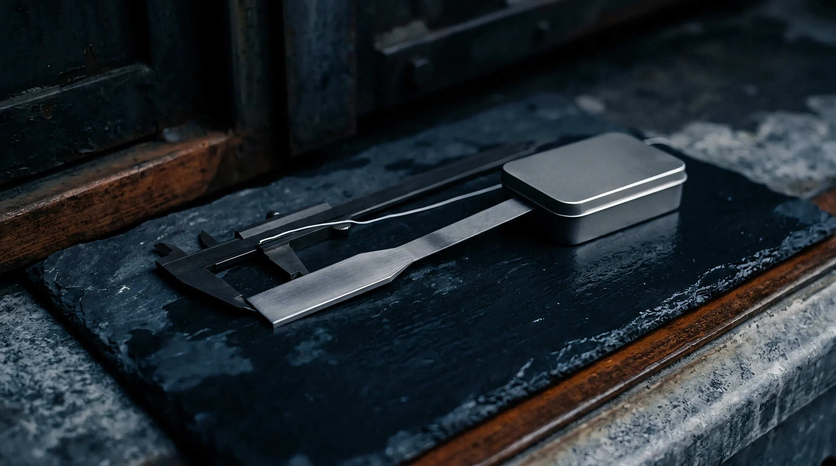
Manual inclinometer walking tools utilize dual contact feet mounted on a rigid base to measure tilt changes with high precision. Spaced exactly three hundred millimeters apart, these instruments house a pendulum-based inclinometer or digital accelerometer that records height differentials between the trailing and leading foot. Operators walk the device step-by-step along marked profile lines, pausing briefly at each step to permit digital sensor stabilization.
Continuous profilers replace step-by-step walking tools with wheeled chassis systems carrying integrated rotary optical encoders and precision inclinometers. Pulled along defined wheel paths at uniform velocity, these units record elevation slope continuously, capturing data points every twenty to fifty millimeters along the aisle axis. Continuous profile graphs highlight sharp localized chatter, step-down joints, and high-frequency undulations that manual three-hundred-millimeter step devices bridge over without recording.
Profilograph recordings output raw elevation profiles alongside differential curvature plots. Evaluating these traces pinpoints the exact physical location of high spots requiring mechanical grinding. By establishing these wheel path baselines immediately after pour stripping, facility managers hold structural contractors accountable for initial surface tolerances before racking installation contractors erect high-density storage grids.
Laser scanner software algorithms do not automatically filter out construction dust and surface laitance when uncalibrated point clouds obscure micro-roughness during site audits.

Curvature
Differential moisture loss between the exposed top surface and the sealed subgrade drives differential slab shrinkage that alters initial elevation profiles. As concrete cures, top-surface moisture evaporates into ambient facility air, shrinking the upper concrete paste layer. The bottom surface, situated against an impermeable vapor retarder, retains moisture and maintains its original dimensions.
This differential volume change forces panel edges and corners to lift upward, converting flat slabs into concave dishes over months of service.
As joint edges curl upward over time and differential drying shifts edge elevations, vapor barriers limit subgrade moisture transfer while concrete mix design controls plastic shrinkage. Understanding the mechanics of curling is essential when interpreting long-term floor baseline stability. A slab that comfortably passes high FF 60 specifications at forty-eight hours post-placement may degrade to FF 35 within ninety days due to progressive drying shrinkage curling at contraction joints.

Mechanics of Top-to-Bottom Moisture Gradients
Rapid evaporative drying at the upper surface contracts the top concrete paste layer while the base remains saturated. The magnitude of slab curling depends directly on concrete mix water content, aggregate volume fraction, curing efficiency, and ambient relative humidity. High water-cement ratios expand total paste volume, multiplying drying shrinkage potential.
When ambient relative humidity drops below fifty percent during initial building commissioning, surface evaporation accelerates, creating severe vertical moisture gradients within the top fifty millimeters of the slab.
Curling profile changes distort elevation profiles severely along saw-cut contraction joints. As joint edges lift off the subgrade, voids form underneath panel perimeters. Unsupported panel corners crack under early forklift traffic, turning smooth joints into broken, uneven edges.
Baseline flatness evaluations must identify whether surface irregularities stem from initial hand-screeding flaws or progressive moisture-driven panel displacement.
| Curing System | 7-Day Retention Efficiency (%) | Mean Edge Lift at 90 Days (mm) | Flatness Index Decay (FF Loss) |
|---|---|---|---|
| Wet Burlap with Sealed Polyethylene Cover | 94.5 | 0.8 | – 12 % |
| Sodium Silicate Liquid Chemical Hardener | 62.0 | 2.4 | – 38 % |
| Dissipating Resin Curing Compound | 78.0 | 1.7 | – 26 % |
| Uncovered Air Drying (Control Baseline) | 41.0 | 4.1 | – 54 % |
Structural Dowel Restraint and Joint Curling Trajectories
Plate dowels along saw-cut contraction joints transfer shear loads but induce localized rotational stiffness that alters panel edge deflections. Square plate dowels housed in plastic sleeves allow horizontal slab contraction while locking adjacent panels into vertical alignment. If dowels bind due to misaligned installation or concrete bleed paste entry into expansion sleeves, concrete panels lock together awkwardly.
Bound dowels induce eccentric restraint forces during thermal contraction, generating severe localized slab warping and spalling along joint lines.
A slab left unsealed in dry indoor conditions loses one F-number rating every fourteen days through differential drying shrinkage.
To identify the structural causes behind progressive floor flatness degradation, engineers evaluate distinct physical failure modes across curing slabs:
- Corner Lift ~ Triangular corner sections delaminate from subgrade support, rising up to six millimeters above mid-panel elevations due to severe top-surface moisture loss.
- Transverse Humping ~ Long, narrow pour strips bow upward along their longitudinal axis when restrained by rigid perimeter wall footings or adjacent slab tie-bars.
- Joint Edge Depression ~ Heavy wheel traffic breaks unsupported, curled joint edges, creating abrupt vertical step-offs that shatter forklift tires and destroy chassis suspension components.
- Mid-Panel Dip ~ Subgrade settlement underneath heavy center loads creates broad basin-like depressions that lower global FL levelness scores without altering local FF flatness metrics.
Whether post-tensioned slab designs can fully suppress long-term corner lifting without supplementary perimeter thickened edges remains an open question among structural engineers.


Dispute
Conflicting elevation reports between slab placement contractors and materials handling equipment vendors create significant financial liability during warehouse commissioning. General contractors aim to secure early sign-off based on broad ASTM E1155 random-traffic F-number compliance. Equipment suppliers reject these baseline reports, pointing to local wheel path slope violations that prevent VNA turret trucks from operating safely at rated speeds.
Resolving these disputes requires rigid contract definitions, standardized inspection timing, and explicit protocol alignment before concrete placement.
Contract terms establish test timing, whereas late surveys blur contractor liabilities and third-party audits help eliminate measurement bias. Writing strict seventy-two-hour inspection windows into general contractor specifications prevents dispute deadlocks. When baseline surveys suffer delays, proving whether non-compliant floor flatness resulted from poor concrete finishing, unapproved concrete mix water additions, or delayed curing application becomes virtually impossible.

Contractual Measurement Timelines and Responsibilities
Defining rigid inspection schedules in tender specifications assigns clear accountability before post-pacing structural movements occur. Contracts must specify exact timing windows for baseline collection, designating certified independent testing agencies to execute all official profiles. If general contractors perform their own profiling without owner oversight, dispute probabilities rise sharply when subsequent third-party audits return lower F-number scores.
Verification protocols must outline exact sampling parameters, including minimum linear survey meters per pour, surface cleaning standards prior to testing, and environmental control requirements. Testing executed while heavy construction equipment drives across freshly placed slabs introduces dynamic chassis vibration that corrupts profile readings. Ambient indoor temperatures and building enclosure status must be documented during every survey run to establish baseline validity.
Arbitration Pathways for Out-of-Spec Floor Sections
Independent third-party survey teams execute blind audit runs to verify elevation calculations when primary records disagree. Arbitration clauses in construction contracts should stipulate that if independent re-surveys confirm floor flatness metrics fall below minimum local values, the contractor covers all audit re-testing fees. If the re-survey proves the floor complies with tender specifications, the challenging party absorbs audit expenses.
When audits confirm out-of-spec surface profiles, contractors must submit formal remedial proposals before attempting surface corrections. Unapproved grinding or burning of high spots often exposes embedded steel reinforcement, degrades surface durability, and voids floor hardener performance warranties. Contractual arbitration workflows guarantee that corrective actions restore operational tolerances without sacrificing long-term structural integrity.
To establish a legally binding baseline verification process, project management teams implement a sequential audit protocol:
- Issue written notice of inspection to all structural and concrete finishing subcontractors twenty-four hours before slab pour execution.
- Inspect column benchmark embed monuments, verifying zero-elevation reference values using closed-loop differential optical leveling.
- Execute primary ASTM E1155 profile runs within forty-eight hours of concrete placement, outputting raw elevation datasets directly to project archives.
- Cross-reference calculated section FF and FL scores against specified target and minimum local values within twenty-four hours of data collection.
- Mark non-compliant pour strips physically on the slab surface using non-staining dye spray, isolating failure zones for independent joint re-measurement.
- Convene an technical arbitration panel featuring structural design engineers and material handling representatives if baseline profile discrepancies exceed five percent.
Measuring floor flatness before strip load application isolates concrete finishing execution from structural subgrade deflections.

Remedy
Targeted mechanical grinding restores defined vehicle aisle tolerances without requiring total slab replacement or high-build floor overlays. Out-of-spec surface profiles interrupt facility commissioning, but precision corrective grinding offers a reliable pathway to restore operational compliance. Grinding operations focus exclusively on high spots identified during baseline profiling, removing minimal concrete depth to smooth profile transitions along defined wheel paths.
While grinding removes localized slab humps and micro-topping overlays fix broad dips, toppings add significant cure time. Mechanical surface corrections must balance profile smoothing against structural concrete cover preservation. Cutting too deep into the slab surface reduces structural cover over wire mesh or top-reinforcing steel bars, inviting moisture-induced corrosion and surface spalling under heavy industrial wheel loads.

Precision Surface Grinding for Defined Narrow Aisle Systems
Robotic grinding equipment cuts narrow paths directly along wheel track paths to eliminate localized transverse slope variations. Modern corrective grinding machinery utilizes computer-guided cutting heads mounted on rigid multi-axle chassis. Software reads baseline profilograph datasets, adjusting head depth dynamically to shave off high humps down to fractional millimeter tolerances without gouging adjacent slab zones.
Continuous profile monitoring tracks grinding progress in real time. Operators execute shallow passes, removing no more than two to three millimeters per pass to prevent micro-cracking concrete surface aggregates. Following grinding execution, operators apply lithium silicate surface hardeners to seal exposed aggregate pores, restoring surface abrasion resistance to match original power-troweled finishing standards.
| Remediation Method | Typical Thickness Cut/Fill Range | Execution Cost per Aisle Meter | Cure Time Before Traffic Re-Entry |
|---|---|---|---|
| Targeted Robotic Bump Grinding | 1.0 mm to 6.0 mm cut depth | Moderate | Immediate (Zero Cure Time) |
| Self-Leveling Cementitious Micro-Topping | 5.0 mm to 15.0 mm fill depth | High | 48 to 72 Hours |
| High-Build Epoxy Resin Overlay | 2.0 mm to 5.0 mm fill depth | Very High | 24 to 48 Hours |
| Local Panel Removal and Recasting | Full Slab Depth (150 mm+) | Extreme | 7 to 14 Days |

Polymer Micro-Toppings and Surface Treatment Economics
Thin-bond cementitious toppings provide self-leveling capabilities across wide-area storage spaces where grinding proved economically unfeasible. When baseline profiles reveal low spots or broad basin depressions, grinding the surrounding high concrete requires excessive material removal across vast areas. Self-leveling polymer-modified toppings flow smoothly over low sections, bonding securely to mechanically scarified concrete bases to restore overall levelness FL values.
Economic evaluation of remedial surface choices must weigh direct application costs against operational facility downtime. While robotic grinding carries higher machinery mobilization fees, it allows immediate vehicle traffic re-entry upon completion. Polymer micro-toppings require extensive shot-blasting surface preparation, primer application, and up to three days of curing downtime, stalling warehouse racking assembly and material handling equipment deployment schedules.
Selecting targeted grinding along defined wheel tracks preserves structural cover over top reinforcement while restoring operational throughput speeds for automated turret trucks.