Quantifying Transient Line Stoppage Cascade Risks in Multi Station High Speed Packaging Lines
Dynamic line stoppage cascades convert brief sub-ten-second equipment pauses into severe line yield deficits by triggering upstream blockages and downstream starvations.

Inventory

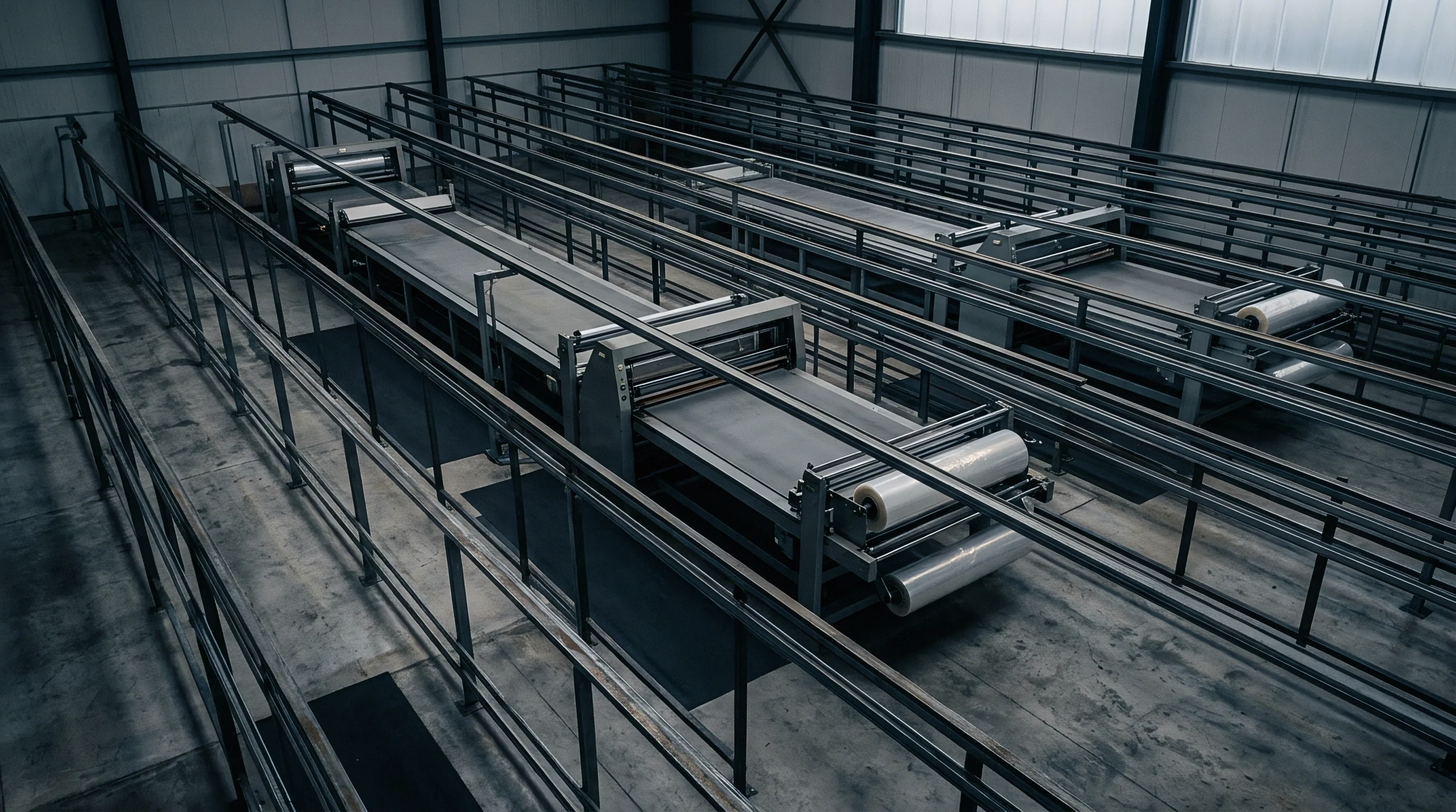
Dynamic Blockage Propagation across Conveyor Interfaces
On a high-speed bottling line rated at 1,200 containers per minute, an unrecorded three-second jam at an optical labeler stops 60 incoming bottles. When that micro-stop repeats twelve times an hour, the conveyor accumulation chain collapses upstream into the monobloc filler-capper, forcing a safety declutch. The line loses 28 minutes of operating output per eight-hour shift without registering a single mechanical breakdown in the maintenance management system.
The factory records show ninety-two percent machine availability while warehouse receipts demonstrate an actual line output running fourteen percent below theoretical quota. That discrepancy originates from transient stoppage cascade physics.
Transient stoppages are short interruptions, typically lasting between one and fifteen seconds, caused by sensor misfires, momentary foil jams, fallen containers, cap feeder bridges, or brief vision rejection pauses. These interruptions resolve automatically or require mere seconds of manual clearing without tooling. Automated supervisory control and data acquisition architectures aggregate downtime using filtering thresholds, frequently discarding operational interruptions under ten or fifteen seconds as nominal process noise.
The physical shockwave travels along intermediate table-top conveyors, accumulation tables, and air tracks, consuming available gaps and forcing adjacent automated stations into forced idle states.
A continuous nominal flow of twenty units per second transforms a five-second sensor pause into an absolute physical displacement deficit of one hundred containers.
Cascades manifest along packaging trains through two physical mechanics: upstream backpressure blockage and downstream delivery starvation. When station downstream from a packaging operation stops, the intervening conveyor fills to maximum density. Once containers accumulate to the upstream station discharge sensor, that upstream machine pauses under backpressure interlock.
Conversely, when an upstream station pauses, downstream conveyors rapidly clear out, depriving the next station of material and triggering an automatic starvation stop.
Quantifying these failure patterns demands isolating the micro-stoppage profile across every isolated unit operation. High-speed primary packaging relies on tight station spacing, meaning small disruptions produce violent surges in dynamic line pressure.
Distinguishing Line Synchronicity Modes
Mechanical coupling models determine how transient interruptions migrate between functional heads. High-speed packaging machinery operates across three distinct connection architectures, each exhibiting radically different surge dampening profiles:
- Direct mechanical pitch synchronisation links stations via common timing screws, transfer stars, or continuous carousels without intermediate buffer space. An instantaneous stoppage at the outfeed star wheel halts the upstream rotary filler in under forty milliseconds to avoid container crushing.
- Decoupled conveyor buffer integration places modular plastic, slat, or belt accumulation conveyors between discrete stations running at independent speeds. Transient interruptions settle within the dynamic float of accumulating packages without disturbing adjacent machines, provided the duration remains beneath buffer absorption thresholds.
- Dynamic electronic line shafting coordinates independent servomotors across adjacent stations through high-speed fieldbus networks. Digital camming ramps individual machine velocities up or down in response to monitored queue depths, absorbing small disturbances by altering instantaneous pitch rather than initiating complete stop-start cycles.
Process engineers frequently treat conveyor spans as simple static storage vessels, calculating buffering capacity by dividing conveyor length by container diameter. This static calculation fails under high-speed operation. Conveyor belts run continuously beneath accumulating units, generating dynamic friction that accelerates wear, induces package shingling, causes line pressure tipping, and introduces mechanical slip factors that reduce actual surge absorption capacity by thirty to fifty percent below theoretical volume.

Propagation

Kinematic Waves in Continuous Material Transport
Material moving along continuous accumulation conveyors behaves kinematically like traffic on a congested highway. Fluid shockwave models describe the propagation velocity of transient line stoppages through dense container flows. When station downstream stops, the point of zero velocity propagates upstream through the container stream as a compressive kinematic wave.
The speed of this stoppage wave depends entirely on container spacing, conveyor surface velocity, and container packing geometry.
The speed of the backward-moving shockwave through an advancing packaging train follows kinematic continuity laws. The container flux represents the product of line linear density and conveyor chain speed. When a downstream unit operation halts, container density surges instantly to the jam packing limit, where packages touch shoulder-to-shoulder or nest within double-lane configurations.
The resulting shockwave moves upstream against container flow at a velocity proportional to the ratio of output rate change to density change.
Air conveyors transporting lightweight polyethylene terephthalate containers exhibit high acoustic and mechanical elasticity, resulting in rapid shockwave transmission speeds exceeding six meters per second. Stainless steel tabletop conveyors carrying heavy glass containers display slower wave propagation speeds due to container mass and interfacial friction coefficients, typically running between one and two point five meters per second. Downstream starvation waves move in the opposite direction at the steady-state speed of the conveyor belt itself, emptying intermediate storage buffers at a fixed rate determined solely by motor drive frequency.

Mechanical Strain Induced by Dynamic Pressure
When containers halt on moving conveyor chains, the continuous relative movement creates substantial friction forces against container bases. The dynamic backpressure accumulates linearly with each additional queued unit. In lines processing thin-walled aluminium cans or lightweight plastic bottles, excessive backpressure causes container ovalisation, scuffing, label tearing, or explosive pop-outs where containers jump the guide rails.
| Interface Segment | Transport Media | Kinematic Wave Speed | Max Dynamic Line Pressure | Elastic Recovery Time |
|---|---|---|---|---|
| Filler to Capper | Direct Transfer Star | Instantaneous Rigid | Zero Gauge Decoupled | Zero Seconds |
| Capper to Labeler | Table-top Slat Chain | 1.85 meters per second | 420 Newtons per meter | 3.80 seconds |
| Labeler to Case Packer | Low Backline Roller Chain | 1.20 meters per second | 180 Newtons per meter | 1.40 seconds |
| Blow Molder to Filler | Pressurised Air Conveyor | 6.40 meters per second | 45 Newtons per meter | 0.65 seconds |
The mechanical energy stored in compressed container queues generates an elastic recovery lag once the downstream stoppage clears. Containers do not immediately resume target operational velocity. Static friction between container bases and conveyor wear strips exceeds kinetic friction, creating an acceleration delay of several hundred milliseconds per queued meter.
As a consequence, even after a downstream micro-stop clears, the upstream station remains interlocked until backpressure drops and queue sensors confirm free movement, multiplying the transient stoppage effect across the physical system.
When engineering teams specify lines based on steady-state mass balances, this recovery hysteresis is completely overlooked, leading to unresolvable output deficits during commissioning.

Damping

Buffer Dynamics and State-Space Thresholds
Mitigating transient cascade risks requires designing buffer zones that isolate stations from short-duration failures. A packaging line buffer functions as an energy dampener, storing containers during downstream blockages and discharging containers during upstream starvations. The effectiveness of any intermediate buffer depends on three physical states: the current fill level, the inbound conveyor speed, and the outfeed acceleration profile.
Lines lacking adequate damping experience total line coupling, where the failure rate of the whole packaging line approaches the sum of the failure rates of every individual station. Under unbuffered coupling, line overall equipment effectiveness drops catastrophic lows. A line with six machines, each possessing ninety-five percent individual availability, yields a combined throughput of roughly seventy-three percent when directly linked without operational buffers.
A packaging line of six unbuffered stations operating at ninety-five percent individual mechanical availability delivers less than seventy-four percent net output.
Intermediate dynamic accumulation systems break this inter-machine dependency. Helical spiral accumulators, bi-directional accumulation tables, and multi-lane serpentines provide decoupled dynamic storage. Effective buffering demands that the accumulation system completely absorbs transient stops within the ninety-fifth percentile of the station failure duration distribution.

Sizing Mechanics for Dynamic Accumulation Systems
Determining optimal buffer capacity requires continuous time Markov chain models or discrete event queueing calculations rather than steady-state heuristics. Standard factory layout heuristics prescribing two minutes of storage everywhere waste floor space and introduce severe product handling damage. Buffer volume must be mathematically derived from the mean time to repair of transient events and the nominal production speed.
Consider a labeling station feeding a secondary carton packer. The carton packer encounters transient stops averaging eight seconds, occurring at a rate of 14 occurrences per operating hour. The packaging line runs at an operational speed of twenty bottles per second.
The buffer requirement between the labeler and carton packer must absorb the entire volume produced during these eight-second episodes, plus the acceleration recovery period of the cartoner. An eight-second stop at twenty units per second produces an instantaneous surge volume of 160 units. If the cartoner takes four seconds to ramp back up from zero to full speed following an interlock clear, an additional forty units accumulate during the acceleration curve.
The minimum functional buffer volume between these machines equals 200 physical containers.
When physical space constraints restrict conveyor length, buffering systems require dynamic overspeed zoning. Under this arrangement, downstream equipment operates at a nominal nameplate speed five to fifteen percent faster than the primary bottleneck machine. This speed differential, known as the overspeed ratio, allows downstream equipment to rapidly empty accumulated buffers once transient disruptions clear, restoring surge capacity before the next failure occurs.
Stochastic
Statistical Characterization of Micro-Down Times
Traditional maintenance records capture catastrophic downtime, such as burned motor windings, broken drive chains, or major mechanical crashes. These events adhere roughly to exponential or Weibull distributions characterized by high mean times between failures and extended repair times. Transient micro-stops, conversely, are governed by heavy-tailed, non-exponential distributions such as the log-normal or Pareto models, displaying severe clustering behavior around short durations.
Station micro-stoppages demonstrate clear operational clustering. An initial micro-stop caused by a skewed packaging carton often leaves debris or misaligned guides that trigger two or three subsequent micro-stops within the next four minutes. Treating micro-stops as purely independent Poisson processes severely underestimates line stoppage cascade risks by failing to account for physical autocorrelation.
Industrial diagnostic data reveals distinct failure parameters across common packaging operations:
- Rotary monobloc liquid fillers register high overall reliability with infrequent transient pauses, averaging zero point six stops per hour with a mean duration of four point five seconds, predominantly triggered by container neck-finish inspection rejections.
- High-speed pressure-sensitive labelers experience frequent transient interruptions, running between eight and eighteen stops per hour, driven by reel web splices, backing tape breakage, and optical registration hunt cycles, with durations averaging six point two seconds.
- Continuous motion case packers generate substantial micro-stop volatility, logging ten to twenty-two events per hour averaging eight point four seconds, caused by flat carton blank pickup failures, hot melt glue nozzle clogging, and corrugated board dimensional variability.
Micro-stop duration variance represents the true governing variable in cascade dynamics. A station with an average stop time of six seconds and low variance poses negligible risk to properly designed buffers. The same station exhibiting a six-second average containing extreme ten-to-thirty-second outliers will routinely overwhelm local buffer zones, triggering catastrophic line cascades.
Discrete Event Simulation Modeling Protocols
Quantifying transient propagation across multi-station lines requires configuring discrete event simulation architectures with empirical high-frequency datasets. Using simple mean values for machine cycle times and stoppage durations inside simulation software yields invalid, over-optimistic throughput forecasts. Simulation logic must utilize empirical probability density functions extracted directly from programmable logic controller event registers logged at high sample rates.
Valid simulation structures incorporate precise conveyor kinetics, including motor acceleration profiles, friction coefficients, container collision physics, sensor placement geometries, and variable motor frequencies controlled by variable frequency drives. Simulating line stoppage cascade risks reveals the exact propagation boundaries within the system, isolating which station micro-stops propagate all the way through to the primary bottleneck, and which disruptions dissipate harmlessly across accumulation belts.
Discrete event models verify that eliminating two-second stops on non-critical machines provides negligible financial return, whereas dampening seven-second stops adjacent to the line filler directly increases overall operational output.

Bottleneck
Isolating Dynamic Constraints in Coupled Networks
In high-speed packaging, the operational constraint is rarely stationary. While the capital-intensive primary machine, typically the filler-capper monobloc, is designated as the nominal design bottleneck, transient line stoppage cascades regularly shift the actual constraint to peripheral packaging machinery. When an unbuffered downstream shrink wrapper experiences repeated eight-second micro-stops, backpressure waves repeatedly force the filler into idle states, transforming the wrapper into the dynamic governing constraint of the entire operation.
Dynamic line bottlenecks shift away from primary filling assets whenever downstream micro-stop frequencies exceed intermediate conveyor recovery rates.
Diligence examiners evaluate line capacity by measuring the operational utilization of the designated bottleneck asset. When supervisory control screens report the filler running at ninety-eight percent of nominal speed while historical output records show eighty-two percent realized volume, dynamic constraint migration is occurring. The filler is operating at full mechanical velocity between interruptions, but transient cascades force frequent micro-stops and controlled decelerations that destroy net volume output.
Detecting dynamic constraint migration demands tracking the operational state profile of the primary bottleneck asset across millisecond intervals. If the primary asset logs substantial cumulative time in starved or blocked states, the machine itself is not restricting output. The true constraint lives upstream or downstream within the coupled cascade path.
Operational Regimes across Coupled Packaging Operations
High-speed packaging trains operate within three distinct hydrodynamic production states depending on product flux, station speeds, and failure frequencies:
- Free flow operating regimes occur when intermediate buffer queues remain below fifty percent capacity, conveyor chains run without backpressure pile-ups, and all transient micro-stops resolve completely within local accumulator capacities. Station throughput runs completely decoupled.
- Metastable surge regimes develop when buffers run between sixty and ninety percent capacity due to elevated micro-stop frequencies at secondary machines. Minor transient events no longer clear cleanly, sending localized kinematic shockwaves across one or two adjacent conveyor sections without completely halting the primary filler.
- Gridlock cascade collapse manifests when buffer capacities exhaust completely. High backpressure forces upstream machines into sequential safety interlocks, downstream conveyors run completely empty, and the entire packaging line synchronizes into a single, highly brittle mechanical train halting on every single station failure.
Once a packaging line collapses into the gridlock regime, restoring nominal steady-state operation requires ten to twenty times the duration of the original triggering micro-stop. Operators must manually clear jammed conveyors, jog machines to clear track sensors, reset safety zones, and wait for intermediate conveyors to refill before the line reaches target operational equilibrium.

Governance
Programmable Logic Controller Sensor Register Auditing
Supervisory control data archives provide unreliable metrics for quantifying transient cascade risks unless the underlying instrumentation and logging routines are rigorously verified. Programmable logic controllers register machine states through physical sensors monitoring infeed presence, discharge backup, drive motor faults, and safety interlocks. When management software polls these controller registers through supervisory open platform communications interfaces at one-second or five-second intervals, micro-stops lasting three or four seconds vanish from recorded downtime tables entirely.
| Station Unit Operation | Recorded Downtime (>15s Events) | High-Speed PLC Log (>1s Events) | Unrecorded Transient Losses | Line Yield Impact |
|---|---|---|---|---|
| Depalletiser Infeed | 14.2 minutes per shift | 38.6 minutes per shift | 24.4 minutes per shift | – 5.1 percent |
| Rinser-Filler Monobloc | 6.5 minutes per shift | 11.2 minutes per shift | 4.7 minutes per shift | – 1.0 percent |
| Roll-Fed Labeler | 18.0 minutes per shift | 52.4 minutes per shift | 34.4 minutes per shift | – 7.2 percent |
| Tray Packer and Shrink | 22.5 minutes per shift | 68.1 minutes per shift | 45.6 minutes per shift | – 9.5 percent |
Auditing packaging operational integrity requires reconfiguring programmable logic controllers to log transitions into internal ring-buffer registers operating at ten-millisecond scan cycles. High-resolution transition logs expose the precise chronology of line stoppages, identifying which station registered the initiating fault and mapping the millisecond-by-millisecond progression of the resulting shockwave across adjacent optical backup sensors.
Diligence examiners must inspect the electrical wiring diagrams and sensor positions on physical conveyors. Machine suppliers routinely place backup interlock sensors too close to station discharge points to cut fabrication costs. Insufficient sensor distances prevent drives from executing smooth deceleration ramps, triggering hard emergency stops that increase container breakage and mechanical wear.
Contractual Commitments and Throughput Acceptance Protocols
Packaging line procurement contracts frequently fail to protect capital buyers against transient cascade vulnerabilities. Standard equipment supply contracts define machine performance guarantees based on short, isolated machine acceptance tests running pristine packaging materials under unrealistically stable conditions. Station acceptance runs of four or eight hours demonstrate mechanical nameplate speed while leaving cascade risks completely hidden.
Buyers must mandate multi-station continuous integration acceptance protocols, requiring uninterrupted line test runs spanning seventy-two consecutive operating hours using production-grade containers, closures, labels, and secondary corrugated cartons. The contractual performance metric must evaluate the integrated system efficiency across the entire line train, governed by unambiguous clauses specifying dynamic buffer validation.
Factory acceptance standards must define net system yield across seventy-two continuous operational hours using variable commercial packaging substrates.
A standard contractual clause enforces that individual station micro-stops lasting less than the agreed design buffer window cannot propagate to the primary filling asset. If a labeler experiences a seven-second stop and the upstream filler slows down or halts during that event, the integration contractor incurs liquidated damages for insufficient buffer engineering. This shifts the financial exposure of cascade dynamics directly onto the turnkey line integrator, ensuring intermediate accumulation mechanics, conveyor controls, and dynamic speed profiling receive proper engineering attention prior to final commercial acceptance.
Equipment suppliers routinely defend cascade-related shortfalls by attributing lost production volume to normal container material variations.
Remedy
Strategic Speed Profiling and Dynamic Line Controls
Resolving line stoppage cascades requires implementing continuous dynamic speed profiling across all integrated conveyor and machine drives. Variable frequency drives connected through deterministic industrial Ethernet networks adjust motor frequencies dynamically based on real-time buffer occupancy thresholds. The packaging line is separated into functional speed zones configured relative to the central process bottleneck.
The primary bottleneck, typically the liquid filler, operates at a strictly constant, unvarying speed to maximize fluid filling accuracy and container stability. All upstream equipment runs at a five to ten percent speed premium relative to the filler, ensuring upstream buffers remain continuously charged to an eighty percent baseline setpoint. All downstream equipment runs at a ten to twenty percent speed premium relative to the filler, ensuring downstream accumulation buffers remain drained to a twenty percent baseline setpoint.
Conveyor drive programs execute multi-stage speed modulation algorithms across intermediate buffer zones:
- Zone clearance ramp protocols increase conveyor motor velocity by fifteen percent the moment a downstream station clears an interlock, accelerating the evacuation of accumulated containers and generating empty belt space to absorb future shockwaves.
- Predictive infeed deceleration sequences track decelerations on upstream machinery, ramping down intermediate conveyor speeds in controlled parabolas to preserve container spacing and prevent abrupt line crashes.
- Modulated low-pressure accumulation cycles cycle stop-and-go conveyor chains into intermittent crawl states during backpressure conditions, minimizing base friction wear and preventing container pop-outs.
These algorithmic speed adjustments keep the entire packaging line in a self-balancing state, dampening micro-stops within conveyor networks before they touch the governing production asset.
Capital Allocation and Mechanical Buffer Retrofitting
When software control adjustments cannot fully mitigate stoppage propagation due to severe spatial limitations, organizations face physical capital retrofit decisions. Inserting dynamic accumulation units requires significant capital investment and physical floor space reallocations. Packaging asset investors must conduct detailed return on investment analyses, comparing the cost of mechanical accumulator installation against the financial value of recovered operational capacity.
Take an operational line producing carbonated soft drinks running at 1,000 cans per minute, generating 0.15 dollars of gross manufacturing margin per packaged unit. Unmitigated transient line cascades rob the operation of 42 minutes of production per twenty-four-hour operating day, equating to an unrecovered volume loss of 42,000 units daily, or 6,300 dollars in lost contribution margin per day. Operating across 300 annual production days, the financial loss totals 1,890,000 dollars annually.
Installing a dynamic vertical spiral accumulator between the filler and the downstream packaging suite requires an all-in capital expenditure of 380,000 dollars, inclusive of conveyor modifications, floor loading reinforcements, engineering integration, and commissioning downtime.
The capital expenditure pays back within seventy operating days. The financial upside of eliminating cascade risks makes buffer retrofitting one of the highest-yielding capital expenditures available in high-speed manufacturing environments. A capital allocator must verify that the root cause of the lost volume is dynamic propagation rather than internal mechanical failure within the primary machine before releasing equipment procurement capital.
Operations directors must verify every physical assumption against high-speed camera validation before committing capital funds to complex accumulator installations.