Hardware Latching Precision Time Protocol Synchronization in Multi-Station Metrology Environments
Hardware latching locks IEEE 1588 network timestamps to physical trigger pulses within nanoseconds, eliminating spatial reconstruction errors in metrology.
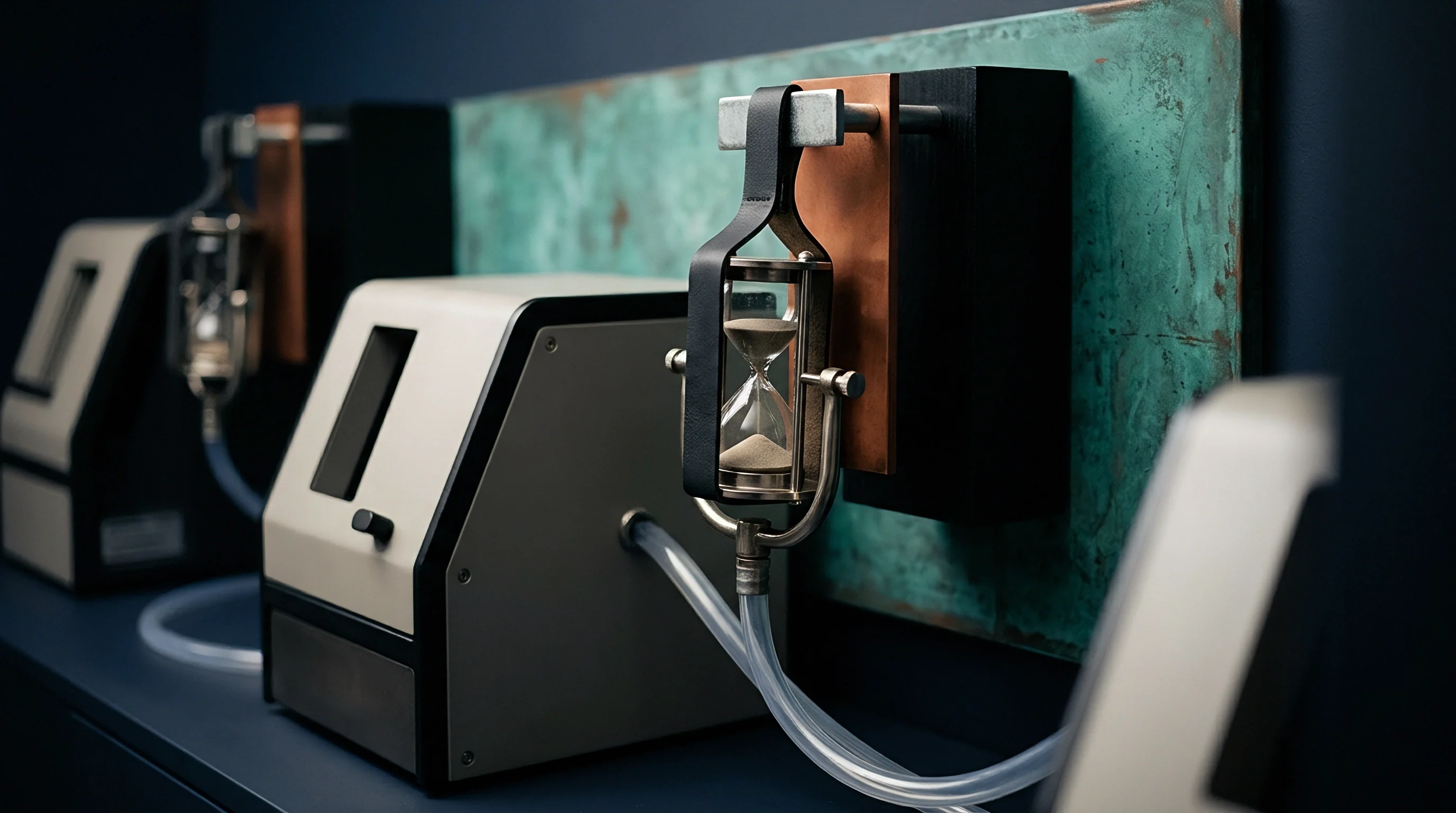

Pulse
An external transverse trigger signal arriving at a metrology node receiver freezes the local counter within ten nanoseconds of physical voltage threshold crossing. Digital laser trackers, multi-camera photogrammetry bars, and tactile probe heads installed across discrete inspection stations depend on this instantaneous counter snapshot to correlate spatial coordinate frames. Standard software-driven polling routines introduce variable interrupt service delays that range from fifteen microseconds to several milliseconds depending on operating system load.
That level of delay destroys point cloud alignment when workpieces move through multi-station inspection cells at production speeds.
Physical signal lines connected directly to network interface silicon bypass kernel stack overhead entirely. When a laser scanner detects an edge or a camera array fires a strobe, the physical voltage rise transitions an input line on the Ethernet transceiver or field-programmable gate array. Hardware circuits instantly transfer the running nanosecond register value from the IEEE 1588 Precision Time Protocol clock into a dedicated trigger register.
The network controller then packages this latch register payload into a data packet that travels across standard Ethernet media without degrading timing fidelity.

Hardware Timestamping at the Physical Layer
Ethernet physical layer devices capture bit arrival times directly at the media independent interface. Signal edges degradation breaks measurement coherence. By capturing the precise instant the Start Frame Delimiter passes the physical connector, the local clock register records event timing independent of operating system latency, buffer queuing, or driver execution delays.
Metrology systems equipped with physical layer timestamping achieve single-digit nanosecond resolution across distributed hardware channels.
Signal line integrity governs input latch precision across long cable runs between stations. Ground loop interference, transmission line ringing, and slow voltage slew rates cause false trigger events or timing uncertainty at the receiver pin. Optical triggers isolate ground loops.
Implementing differential signaling over twisted pair wiring maintains steep edge transitions across twenty-meter station spans, keeping trigger uncertainty below two nanoseconds.
Physical edge sharpness determines timestamp repeatability across distributed sensor channels.

Event Input Registers and Latching Dynamics
General purpose input lines connect directly to the counter latch hardware inside the network controller. Upon detecting a configured voltage threshold, the hardware executes a non-destructive copy of the sixty-four-bit or eighty-bit time accumulator into a shadow register. This hardware action completes within one clock cycle of the internal timing core, eliminating software jitter from the event record.
Multiple metrology stations operating in parallel present distinct latching failure modes when exposed to plant noise or electrical fast transients. Sensor channels must isolate real trigger events from high-frequency spurious pulses generated by nearby variable frequency motor drives or welding equipment.
- False Trigger Insertion occurs when ambient switch-mode noise crosses the input latch logic threshold, generating invalid spatial data frames that corrupt point cloud alignment.
- Register Overrun Condition arises when trigger pulse rates exceed the register readout capacity, causing uncollected timestamps to be overwritten before transmission.
- Propagation Delay Asymmetry manifests along differential wire paths when unequal conductor lengths skew physical signal arrival times across multi-axis stations.
- Threshold Slew Softening develops when capacitive loading flattens voltage rise times, introducing timing jitter as threshold crossing times shift with temperature.
When input threshold detection circuits fail to reject ground bounce, spatial coordinate calculations combine measurements taken at different physical instants, introducing unrecoverable geometry errors into the central quality dossier.


Jitter
Phase fluctuations in the reference clock stream introduce spatial uncertainty into dynamic point cloud measurements. Multi-station metrology installations rely on continuous clock synchronization over standard Ethernet topologies to maintain a unified temporal coordinate system. Variations in packet transmission delays across network switches degrade local oscillator synchronization, causing station clocks to wander relative to the grandmaster clock reference.
Network delay variation originates from frame queuing in switches, physical layer physical media transitions, and physical length variations in network cabling. Standard network traffic competing with time synchronization packets creates non-deterministic packet delays. Metrology networks mandate prioritized packet treatment and precision hardware transparent clocks to measure and subtract switch residence time from packet transit calculations.

Asymmetric Delay Compensation in Fiber and Copper
Signal propagation speeds vary based on dielectric constant and conductor temperature variations. Physical cable lengths alter delay symmetry. IEEE 1588 offset calculations operate on the assumption that forward and reverse path transmission delays are identical.
An uncorrected ten-nanosecond asymmetry between path directions generates a five-nanosecond clock offset error at the destination station node.
Station cabling paths exposed to thermal gradients in manufacturing environments suffer baseline propagation shifts. Single-mode optical fiber exhibits a delay shift of approximately forty picoseconds per kilometer per degree Celsius. Copper Ethernet cabling exhibits larger thermal delay coefficients, changing propagation latency by up to 0.04 percent per degree Celsius.
Calibration routines must measure baseline asymmetry using bidirectional physical layer measurements during initial station setup.
| Profile Standard | Physical Layer | Max Node Jitter | Timestamp Latch Accuracy | Primary Constraint |
|---|---|---|---|---|

Oscillator Phase Noise and Clock Recovery
Frequency synthesis loops generate short-term timing variations when locked to incoming Ethernet packet streams. Phase noise pollutes spatial reconstruction. Local voltage-controlled crystal oscillators inside inspection heads must smooth out short-term network delay variation while following long-term drift of the central grandmaster reference.
The phase-locked loop filter bandwidth determines how effectively the station rejects network transit noise.
Narrow loop bandwidths attenuate network packet jitter but increase station susceptibility to local thermal oscillator wander. Wide loop bandwidths force the local clock to track short-term packet delay variations, transferring network noise directly into timestamp latch records. Metrology node clock servos require tuned second-order filter loops matched to the specific crystal oscillator characteristics at each inspection node.
At a scanning speed of two meters per second, a fifty nanosecond timing error translates to one hundred micrometers of spatial offset.
When station builders express frustration over persistent spatial alignment errors across optical tracking zones, equipment vendors routinely blame local network switch configuration rather than addressing physical layer timestamp calibration deficiencies inside their sensor controllers.


Topology
Network architecture decisions define the accumulation of packet delay variation across multi-axis scanning nodes. Distributed metrology cells spanning large assembly halls demand structured network layout planning to prevent synchronization signal degradation between the master timing reference and distant target stations. Star, line, and ring architectures exhibit distinct delay propagation properties that directly affect timestamp latch accuracy.
Direct point-to-point connections from a central boundary clock to individual inspection nodes eliminate switch cascade delays. Cascading multiple Ethernet switches in a linear bus architecture adds cumulative residence time noise at each hop. Boundary clocks eliminate cascade delay.
Station layout design must balance network cabling complexity against timing precision targets dictated by part tolerance limits.

Transparent Clock versus Boundary Clock Cascade
Intermediate switches measure packet residence time to update correction fields within passing timestamp frames. End-node clocks read these correction fields to compensate for switch processing latency. End-to-end transparent clocks preserve original message header structures while updating timing offset fields, providing efficient synchronization across small-scale inspection clusters.
Boundary clocks terminate incoming time-synchronization connections from the grandmaster and serve as local timing masters for downstream nodes. This separation shields downstream nodes from upstream packet delay noise. Large multi-station facilities with dozens of optical sensors utilize boundary clock hierarchies to scale station counts without degrading station latch precision.
- Install a high-stability Rubidium grandmaster clock reference at the primary metrology server rack.
- Run equalized length single-mode optical fiber trunks from the master rack to regional boundary clock switches situated at each inspection bay.
- Connect station hardware triggers to dedicated local PHY latch inputs using shielded low-loss coaxial cabling.
- Measure cable path asymmetries between boundary switches and metrology heads using loopback latency testing.
- Program delay offset values directly into individual node storage registers to cancel fixed cable delays.

Queue Delays and Packet Prioritization
High-priority IEEE 802.1Q traffic classes isolate time synchronization frames from bulk coordinate payload transmissions. Switch latency destroys temporal lock. When large point cloud files transmit across shared physical media simultaneously with time packets, unprioritized timing frames stall behind maximum transmission unit data packets, introducing microsecond-level queuing delays.
Time-Sensitive Networking standards extend IEEE 1588 capabilities by enforcing scheduled traffic windows. Frame preemption allows network switches to pause low-priority data packet transmission to allow time synchronization packets to pass through without switch queue delay. Implementing scheduled traffic queues ensures time synchronization packets experience zero contention with measurement payload data.
IEEE 1588 clause 11.2 mandates symmetry in physical path delay calculations to keep offset calculations valid.
According to standard equipment supply framework agreements, any network infrastructure deployment that fails to deliver IEEE 1588 Boundary Clock functionality across all intermediate nodes forfeits compliance certification for multi-station dynamic metrology integration.

Drift
Frequency variation in local station crystal oscillators causes time offset degradation when grandmaster updates pause. Temperature changes, crystal aging, and mechanical vibration alter oscillator resonant frequencies over operational shifts. In high-speed measurement applications, unchecked frequency drift pulls station clocks out of alignment, introducing systematic dimensional skew into scanned part geometries.
Thermal stability dominates oscillator selection for plant-floor metrology nodes. Uncompensated temperature-compensated crystal oscillators wander by several parts per million across typical shop floor ambient swings. Oven-controlled crystal oscillators maintain internal crystal temperature stability within a fraction of a degree Celsius, reducing frequency wander to parts per billion and holding microsecond timing coherence across extended holdover periods.

Thermal Coefficient Impacts on Local Oscillators
Ambient temperature fluctuations in industrial inspection cells shift crystal resonant frequencies by several parts per million. Thermal shifts alter quartz frequency. A temperature change of five degrees Celsius occurring over a two-hour manufacturing run shifts standard crystal frequency enough to accumulate tens of microseconds of timing offset if network synchronization updates stall.
Metrology stations located near HVAC ducts or heat-treating equipment experience rapid thermal cycles that stress local timing loops. Clock servos must adjust lock parameters to track these thermal frequency shifts without overreacting to short-term network jitter. Local enclosure thermal insulation stabilizes timing hardware against transient air currents.
Selecting appropriate oscillator hardware requires evaluating spatial accuracy targets against node cost limits:
- Standard TCXO Modules offer low cost but exhibit thermal drift up to one part per million, limiting holdover precision to brief network dropouts.
- Oven Controlled OCXO Units maintain ppb stability across variable thermal environments, providing microsecond holdover capacity over several hours.
- Atomic Rubidium References eliminate long-term drift entirely, serving as ultra-stable master sources for high-precision aerospace wing-alignment cells.
- MEMS Timing Devices offer high resistance to physical shock and vibration in dynamic robot-mounted sensor applications at the cost of elevated phase noise.

Metrology Coordinate Frame Alignment over Time
Spatial registration between separate optical tracking heads breaks down when temporal offset exceeds ten microseconds. Consider a dynamic scanning cell inspecting a large aerostructure component moving on a rail at 2.5 meters per second. The cell utilizes four independent optical scanning nodes synchronized over an Ethernet backbone.
Assume an oscillator drift rate of 0.5 parts per million on one node combined with a network update interruption lasting 100 milliseconds. The local station clock drifts by fifty nanoseconds during the dropout window. At a scanning velocity of 2.5 meters per second (2.5 micrometers per microsecond), a fifty nanosecond timing error creates a spatial measurement error of 0.125 micrometers.
If the holdover extends to ten seconds due to network link recovery issues, clock drift reaches five microseconds, creating a spatial coordinate error of 12.5 micrometers, which consumes twenty-five percent of a fifty-micrometer part tolerance budget.
Crystal stability dictates sync holdover.


Audit
Diagnostic validation of time synchronization integrity relies on continuous monitoring of offset registers across all metrology stations. Quality control protocols require logged proof that every spatial point was captured while node clocks remained within established offset limits. Timestamp records containing missing sync flags or offset spikes must trigger automated part re-inspection flags during execution.
Network management tools harvest time synchronization telemetry via Simple Network Management Protocol or Dedicated PTP management messages. Parameters collected include master-to-slave delay, slave-to-master delay, mean path delay, and phase offset variance. Analyzing these logs isolates degrading network cables, misconfigured switch ports, or failing local oscillators before timing errors compromise quality checks.

Timestamp Verification Procedures and Log Analysis
Offset logs captured at one-second intervals reveal network asymmetric delays and clock servo instability. Timestamp logs establish physical truth. Calibration software cross-references hardware trigger timestamp logs against spatial coordinate data packets to confirm matching sequence IDs and timing coherence.
Statistical analysis of offset log distributions yields critical stability metrics. A healthy metrology node log exhibits a Gaussian offset distribution centered on zero with a standard deviation under twenty nanoseconds. Skewed distributions or sudden step changes in offset history indicate packet delay asymmetry or physical signal reflection issues on hardware trigger lines.
| Inspection Mode | Max Velocity | Max Allowable Offset | Max Offset Jitter | Holdover Limit |
|---|---|---|---|---|

Acceptance Stage Gates for Multi-Station Calibration
Commissioning engineers evaluate offset variance statistics before authorizing multi-head laser scanner deployment. Metrology frames demand absolute clock lock. Station readiness sign-off requires continuous uninterrupted clock lock across a forty-eight-hour soak test within the production environment, operating under full factory network load conditions.
Calibration records confirm clock integrity. The final commissioning dossier includes raw offset logs, cable asymmetry calibration records, hardware trigger latch test traces, and spatial artifact verification measurements. Passing these verification gates ensures the multi-station inspection system delivers reliable, traceable dimensional data throughout its service life.
Continuous counter monitoring provides proof of temporal lock during dynamic measurement runs.
What diagnostic protocol definitively proves that a transient fifty-nanosecond offset spike in a single tracking head did not corrupt the merged volumetric point cloud during a high-speed scan pass?