First Pass Yield Degradation Mechanisms in High Volume Manufacturing Lines
First pass yield degradation stems from compounding stochastic variance, tool wear, and thermomechanical drift, requiring precise process window defense.


Noise
In high-volume assembly, small input variations compound quickly at high cycle rates and pull down overall yield. Minor shifts in raw material purity, room humidity, power grid harmonics, or static discharge produce transient defects that pass right by basic inline sensors. Because these intermittent anomalies accumulate across multiple stations, first pass yield drops without ever tripping a single-station alarm threshold.
Operators then tend to blame isolated mechanical failures, missing the broader variance driving the problem.
On automated electronics and mechanical lines running over one thousand units an hour, random variance in incoming parts changes how machines handle them. Slight roughness variations on raw metal stock alter friction coefficients during stamping, drifting position by less than twelve micrometers. That shift stays well within tolerance for the individual part, but it breaches cumulative stack-up limits five stations downstream.
An intermittent defect disappears during static bench tests and comes right back at full production speed.
The baseline first pass yield drops three percent for every half-degree Celsius ambient temperature drift across an unconditioned assembly enclosure.
Environmental stability directly controls repeatability on fast lines. A fifteen percent swing in relative humidity alters how fast static charges dissipate on polymeric carriers, which shifts placement retention forces on pick-and-place heads. As static builds up, components rotate by fractions of a degree during fast axis deceleration.
That small twist leads to misaligned pins during automated soldering, creating micro-shorts that show up only during final functional screening.

Quantifying Stochastic Process Spikes
Process instability often shows up as low-level yield chatter rather than full-blown downtime. Line logs will capture brief dips in first pass yield around shift changes or thermal shifts. Monitoring station-level voltage often reveals unregulated servo drives dumping electrical noise into sensor lines and causing false optical triggers.
The system sees a properly seated part as misaligned, firing off rejection routines that end up damaging good parts following behind in the chute.
Power quality audits on automated packaging lines show that high-frequency switching noise from nearby heavy machinery adds up to two hundred millivolts of ripple to analog sensor lines. That noise shifts the zero-point on laser displacement sensors, distorting real-time gap readings during fast adhesive dispensing. The bead thins out below spec for bursts shorter than fifty milliseconds, producing unbonded seams that pass downstream unnoticed until failing leak tests three hours later.
| Variance Vector | Operational Range | Failure Threshold | FPY Reduction |
|---|---|---|---|
| Ambient Relative Humidity | 35% to 65% RH | > 58% RH | 1.8% to 3.2% |
| Input Sheet Thickness Drift | 0.80 mm +/- 0.02 mm | > 0.815 mm | 2.4% to 4.1% |
| Mains Power Voltage Ripple | 24 VDC +/- 0.5 V | > 1.2 V peak-to-peak | 0.9% to 1.5% |
| Thermal Enclosure Gradient | 21 deg C to 28 deg C | > 25.5 deg C | 2.1% to 3.8% |

Raw Material Lot Variance and Input Degradation
Lot variations across the supply chain introduce subtle shifts in material properties that erode calibrated process windows. Tensile strength changes inside a single supplier coil lot can swing springback angles during precision bending by up to one point five degrees. Cells set up for nominal properties end up throwing parts out of geometric tolerance whenever a batch runs near the lower specification limit.
Operators then tweak machine parameters by hand, introducing line-to-line and shift-to-shift variance that destabilizes the process even more.
Shifts in resin chemical composition can alter melt flow index values by ten to fifteen percent from one batch to the next. In high-speed injection molding or dispensing, those flow variations change cavity fill rates and clamping force distribution. Parts molded from thicker batches hold onto internal stresses that distort dimensions as they cool post-mold.
Downstream, that warping keeps parts from seating cleanly into stamped aluminum housings, cutting yields at the final joining station.
Yield drops are often attributed to operator error or uncalibrated equipment, even while incoming raw materials match mill certification sheets to the letter.


Warp
Thermal gradients and internal mechanical stress in multi-layer parts cause sharp geometric changes during fast processing. Mismatched thermal expansion coefficients across bonded layers create latent shear stress that pulls components out of flat during heating or cooling. Once a substrate warps past planar tolerance limits, automated handlers can’t draw a reliable vacuum seal or clamp properly.
The resulting placement errors wreck downstream joining, soldering, or encapsulation, driving yield down immediately.
On fast electronic assembly and structural bonding lines, swift thermal cycles set up heavy internal strain. Substrates going through localized reflow or laser welding absorb heat unevenly through their thickness. Top layers expand fast while cooler lower layers hold back, forcing the board to bow up or down.
If that deflection goes over fifty micrometers across a hundred-millimeter span, surface-mount parts float off their alignment pads or form solder bridges as the joint freezes.

Thermomechanical Stress Fields in Assembly
Assemblies combining glass-reinforced polymers and copper traces distort non-linearly when thermal cycles cross glass transition temperatures. Stresses frozen into the laminate during pressing release unevenly when heated again, twisting the substrate along its diagonal and throwing off registration marks relative to camera coordinates. The vision system misinterprets component position, dropping fine-pitch ICs far enough off-center to cause terminal solder bridges.
Aggressive thermal ramps make internal strain gradients much worse. Lines pushed for throughput trim heat exposure times to the absolute limit, ramping temperatures at rates up to four degrees Celsius per second. Downstream cooling nozzles then blast room-temperature air onto hot assemblies, causing localized thermal shock.
The outer edges shrink faster than the core, cracking internal trace layers or warping the structure so badly it won’t fit into its enclosure at final assembly.
Standard ISO 1101 geometry specifications dictate that planarity tolerances must evaluate the total spatial envelope between two parallel planes across the entire active datum.

Phase Change Kinetics and Dimensional Drift
Polymers, adhesives, and solders change volume as they shift phases, throwing off dimensional stability if cooling varies across a run. Exothermic curing in structural epoxies raises local temperatures inside thick joint areas. If that heat escapes unevenly, cross-linking density varies across the joint section.
The fully cured adhesive holds onto unbalanced stress vectors that continue pulling thin-walled mating parts out of shape over the next twenty-four hours.
Solder solidification creates similar problems on high-speed SMT lines. Cooling too quickly locks non-equilibrium intermetallic structures into the interfaces, making joints brittle, while cooling too slowly encourages dendrite growth that bridges conductors. Uneven airflow in reflow cooling zones varies local heat removal across wide boards, warping sections unevenly and straining fresh solder joints until they form latent open circuits.
A line running aggressive thermal ramps will turn out flat parts only until ambient shop-floor drafts shift or cooling water temperatures creep up.

Wear
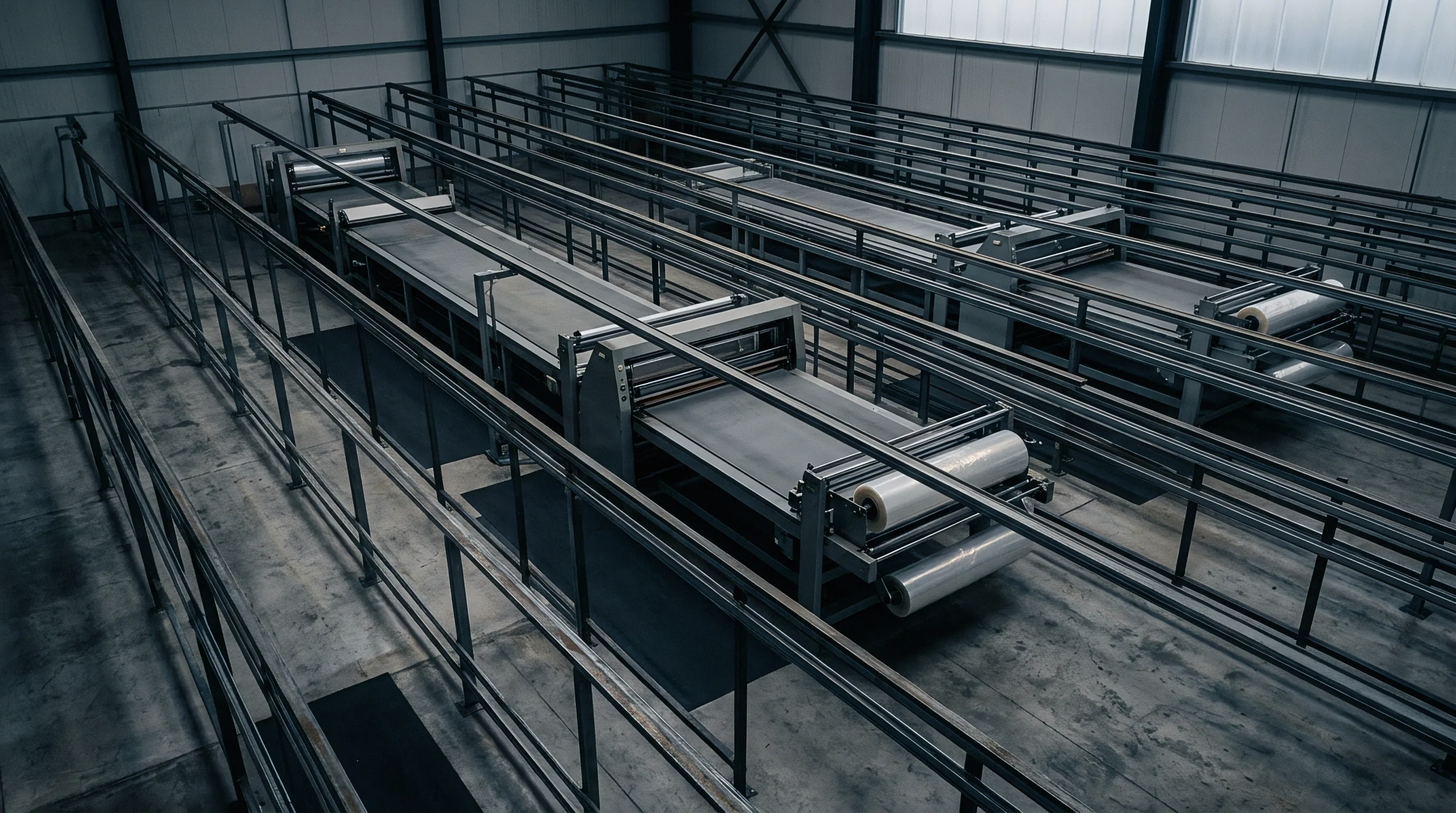
Tool wear, mechanical abrasion, and nozzle erosion steadily degrade capability over long production runs. As cutting edges dull, punch dies round off, and fluid orifices open up, part dimensions drift away from nominal. This wear happens continuously, yet defect counts stay at zero right up until cumulative drift crosses a specification limit.
Once that line is crossed, scrap accumulates quickly until operators shut down the line, clear jams, and replace the worn tooling.
Progressive die stamping and precision trimming show this decay clearly. Hardened tool steel punches lose their sharp cutting edge after about three hundred thousand strokes. The dull edge forces material to deform plastically rather than fracture cleanly, leaving burrs along cut edges that exceed fifty micrometers.
Downstream, those burrs scrape protective insulation off wiring harnesses or keep mating sheet metal components from sitting flat.

Mechanical Degradation and Micro Burr Formation
Mechanical wear alters force behavior in high-speed drive systems. Linear guides, ball screws, and cam followers suffer micro-pitting and surface wear that add backlash to positioning axes. A fast pick-and-place gantry with just five micrometers of axis backlash will overshoot during hard deceleration.
The head vibrates at its resonant frequency as it stops, dropping micro-components off-target and causing short circuits or mechanical interference.
Friction rises as protective plating wears away. Titanium nitride and diamond-like carbon coatings on forming mandrels steadily erode under continuous contact with glass-filled polymers or raw aluminum strip. Once base metal rubs directly against stock, friction coefficients jump by up to forty percent.
Pushing actuators harder to complete strokes flexes the press frame, pulling dies out of alignment and accelerating tool chipping.

Nozzle Wear Dynamics in High Velocity Dispensing
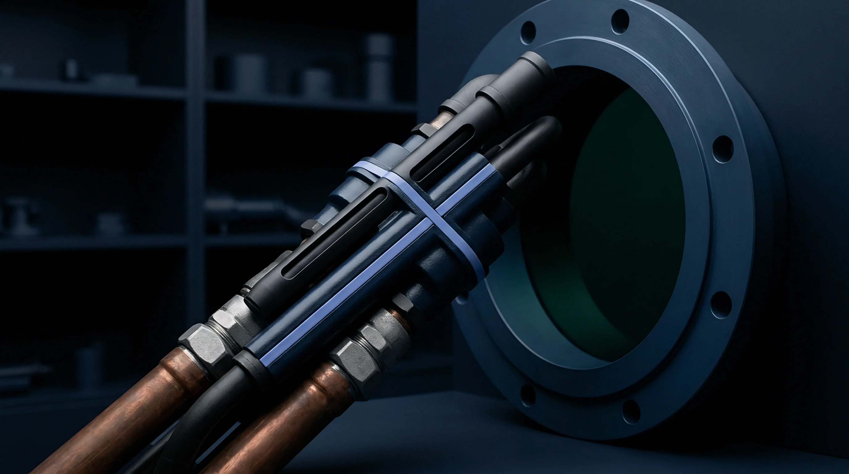
Abrasive fillers in structural adhesives, thermal compounds, and potting resins continuously scour fluid channels. Ceramic and metallic particles wear away tungsten carbide nozzles, opening up internal diameters during long production runs. A mere two percent increase in nozzle diameter boosts volumetric flow by more than eight percent at constant pump pressure, producing squeeze-out that contaminates optical sensors or spills outside bond lines.
Erosion disrupts nozzle flow profiles as well. As symmetrical internal geometry wears into irregular or elliptical shapes, fluid streams off-axis during high-speed jetting. Adhesive droplets land hundreds of micrometers off-target, bridging tight clearances or starving critical bond zones.
Those unbonded areas fail ultrasonic inspection, forcing hand rework or scrapping high-value subassemblies outright.
Progressive wear mechanisms degrade line repeatability through identifiable physical interactions:
- Cutting edge radius dulling increases burr height, requiring higher shearing forces and generating metallic debris that short-circuits internal electronics.
- Abrasive fluid channel erosion expands internal nozzle diameters, driving excessive material discharge that overflows critical clearance zones.
- Linear drive mechanical backlash causes high-deceleration positional oscillation, dropping placement accuracy during fast gantry maneuvers.
- Forming mandrel coating striping elevates friction coefficients between tool and work, flexing press structures and causing uneven part deformation.

Worked Case on Tooling Endurance and Scrap Escalation
Consider a terminal stamping module running at six hundred strokes per minute over a continuous seven-hour shift. The module uses a multi-station progressive die to produce copper-alloy connector pins for automotive harnesses. The critical characteristic is pin crimp wing height, specified at 1.20 millimeters with a symmetric tolerance of plus or minus 0.03 millimeters.
Initial capability studies on fresh tooling show a process capability index of two point one, with a nominal pin height of 1.202 millimeters and a standard deviation of 0.004 millimeters.
Tool steel wear rounds the punch radius at 0.005 micrometers per hundred strokes. As that edge dulls, material flow shifts, pushing crimp wing height up by 0.001 millimeters every forty thousand strokes. At the same time, punch impact vibration wears the die shoe guide bushings, expanding standard deviation from 0.004 millimeters to 0.009 millimeters over four hundred thousand cycles.
By stroke three hundred and twenty thousand, mean crimp height has drifted to 1.210 millimeters.
Calculating upper-tail defect probability shows how fast first pass yield drops. Combining the mean shift and expanded variance drops the operational process capability index to 0.74 by cycle four hundred thousand. At that point, the probability of producing a crimp wing above 1.230 millimeters hits zero point six five percent.
On a line running thirty-six thousand pins an hour, that shift throws off two hundred and thirty-four scrap parts every hour. Without a stop for tool regrinding, shift scrap reaches sixteen hundred defective units, eating profit margins and swamping offline inspection.
An automotive actuator ramp incurred a ninety-thousand-dollar scrap write-off because automated vision systems failed to detect progressive punch wear until burrs reached three times allowable drawing tolerances.
Clamp
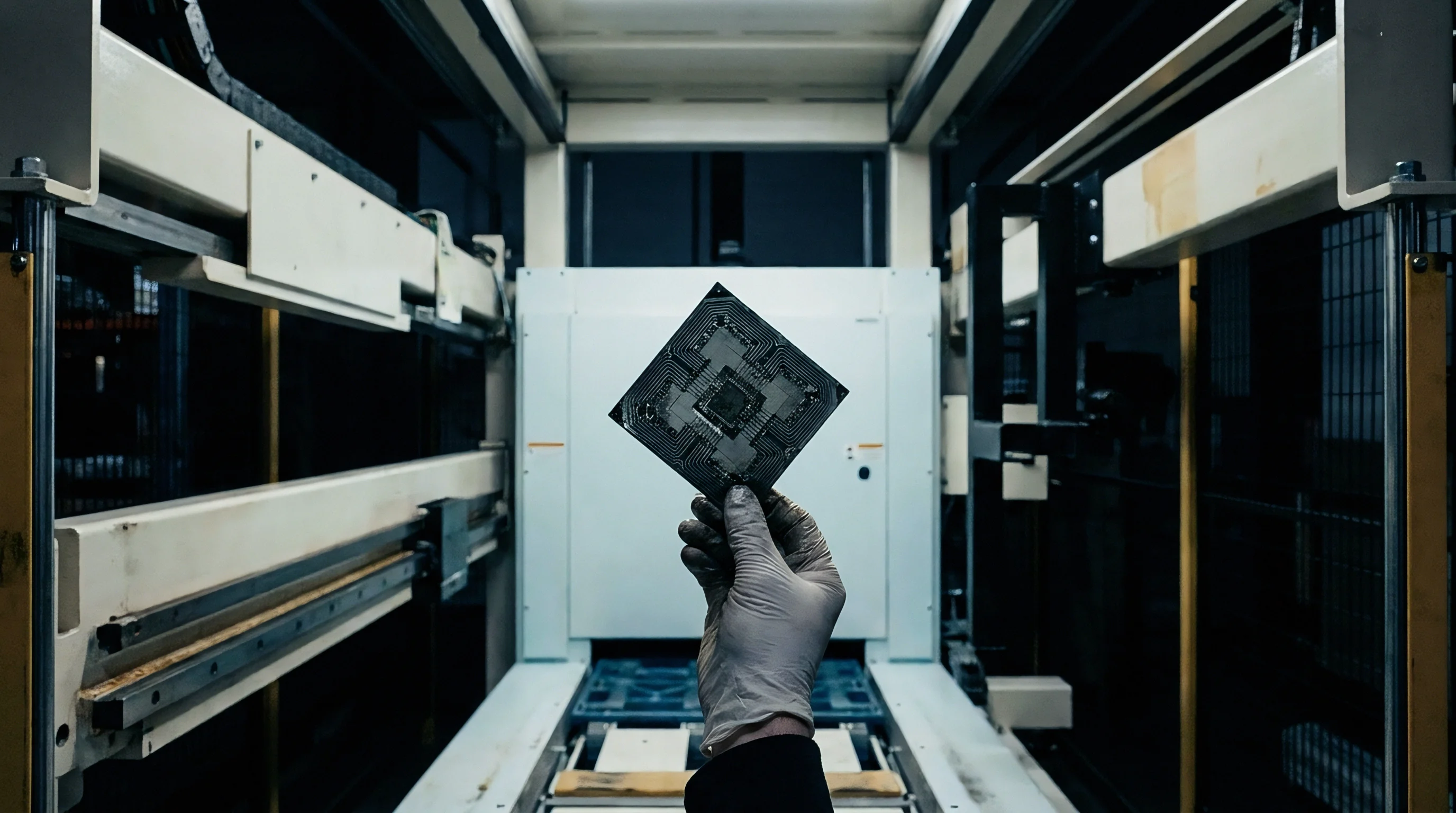
Workholding mechanics govern positional repeatability across automated processing steps. If clamping fails to hit precise datum registration, part positions drift relative to tool axes, laser paths, and vision coordinates. Loss of clamping force, trapped debris on reference pads, and worn pneumatic actuator seals all add compliance to fixturing assemblies.
That compliance permits micro-movements during high-acceleration strokes, causing errors that compromise the finished assembly.
Pneumatic and hydraulic workholding often struggles with pressure stability under continuous multi-axis operation. Shop air drops during peak demand reduce clamping force on automated pallets. When clamping drops, parts shift slightly under the impact of fast assembly heads or cutting tools.
Moving just five micrometers during laser welding pushes the seam off the joint interface, leaving partial-penetration welds that fail tensile pull testing.
Why Do Fixture Pin Tolerances Decay Unnoticed?
Locator pins defining primary and secondary datums take continuous friction during automated loading and unloading. Hardened steel pins cycling through five thousand subassemblies a day wear flat spots and lose diameter from abrasive contact with metal or composite parts. Once pins wear down by ten to fifteen micrometers, clearance inside the locating hole opens up.
The part sits loosely before clamps lock down, introducing rotational and translational alignment errors right from the start.
Rotational misalignment scales positional error with distance from the datum pin. A clearance slip of just zero point zero two millimeters at a primary pin creates over zero point one millimeter of drift at a feature five hundred millimeters away. Downstream screwdriving, component insertion, or dispensing targeting that edge strikes off-center, stripping threads, cracking plastic housings, or missing sealant channels outright.

Vacuum Chuck Contamination and Surface Distortion
Vacuum chucks and suction end-effectors require clean surfaces to clamp thin-walled substrates evenly. On busy production floors, airborne dust, coolant mist, and raw material flash settle onto vacuum plates. A single trapped particle thirty micrometers high keeps the substrate from seating flush against the datum.
The vacuum pulls flexible material down around that particle, creating a small dome on the top surface.
During laser micro-machining or optical printing, that local height bump lifts the surface out of the focal plane. The laser spot defocuses, spreading beam diameter while power density drops below ablation thresholds. The tool cuts shallow or wider kerfs, opening circuits or shorting adjacent trace paths.
Operators clearing tables by hand frequently scratch the surface or leave packed debris behind, keeping scrap high across following shifts.

Datum Shift Protocols and Line Transfer Registration
Transfer systems between stations must maintain exact datum registration when moving work-in-progress. Pallet conveyors rely on shot-pins or lift-and-locate units to position pallets at every cell. Worn bushings or dirt packed inside receiver holes keep the pallet from hitting hard mechanical stops, locking the entire fixture into place with a systematic offset relative to station tooling.
Standardizing fixture qualification requires executing a rigorous diagnostic procedure before releasing lines for volume production runs:
- Clean locator pads and datum pins with solvent wipes to remove residual oils, chips, and particulate debris.
- Measure locator pin diameters across orthogonal axes using micrometer gauges calibrated to sub-micron standards.
- Verify pneumatic supply pressure stability at full line actuation, ensuring pressure drops stay below two percent of nominal setting.
- Lock a calibrated master gauge plate into the fixture and measure surface planarity with dial indicators across all support points.
- Apply maximum clamping force and record spatial deflection across structural datum features using laser displacement sensors.
- Cycle clamping actuators fifty times continuously, measuring locator pin return position repeatability after each release.
Under Section 8.4 of the IATF 16949 quality standard, modification protocols mandate that any change to workholding geometry or clamping pressure triggers a full production part approval process re-validation before volume shipping can resume.


Metrology
In-line inspection equipment and automated screening set the baseline for reported first pass yield. When gauges drift, wear, or lack repeatability, they produce false rejections and false acceptances that mask true performance. False rejections (alpha risk) toss good components, artificially lowering yield and driving up scrap costs.
False acceptances (beta risk) pass bad units downstream, leading to field failures or severe station jams further down the line.
Gauge repeatability and reproducibility deteriorate rapidly in continuous high-volume production. Optical lenses collect dust, oil films, and debris that blur image contrast and edge resolution. Shop-floor vibration rattles camera mounts and laser sensors, shifting calibration offsets over a shift.
Once measurement system variability exceeds ten percent of the total tolerance band, the inspection system can no longer separate actual part defects from gauge noise.

Gauge Repeatability and Consumer Risk Amplification
Measurement uncertainty shrinks usable process windows directly. When an inspection tool shows high variance, quality engineers pull upper and lower test limits inward from engineering specs to avoid shipping bad parts. This guardbanding eliminates beta risk, but it spikes alpha risk.
Parts with physical dimensions perfectly inside print tolerances get scrapped if their measured values fall inside the guardband zone.
| GR&R % of Tolerance | Guardband Width (mm) | False Reject Rate (%) | False Accept Rate (%) |
|---|---|---|---|
| < 10% (Capable) | 0.002 | 0.05% | < 0.01% |
| 10% to 20% (Marginal) | 0.006 | 1.20% | 0.15% |
| 20% to 30% (Poor) | 0.012 | 4.80% | 0.85% |
| > 30% (Unacceptable) | 0.022 | 11.50% | 3.40% |
Guardbanding calculations show that when gauge repeatability and reproducibility hits twenty percent, guardbands eat up to twenty-four percent of total print tolerance. The manufacturing line must run tighter than print specifications just to pass automated inspection. If process centering drifts even slightly, false rejects trigger automated line stops, idling capacity while technicians chase ghost defects.

Automated Optical Inspection Calibration Drift
Vision systems calibrated to fixed lighting lose accuracy as LED sources age and factory lighting shifts. LED arrays lose brightness over time, dimming target surface illumination. Lower light reduces signal-to-noise ratios in image captures, leading sub-pixel algorithms to miscalculate hole diameters, lead pitch, and scratch widths.
The inspection engine starts flagging normal surface texture as structural cracks, driving up false rejects.
Thermal expansion in camera mounts adds another source of optical error. Aluminum camera brackets mounted directly over hot equipment expand across a shift, moving sensors relative to reference planes. A height shift of just two millimeters changes image magnification on non-telecentric lenses, altering the pixel-to-millimeter calibration.
Six hours into a run, the system outputs systematic size errors, reporting dimensional drift on parts that haven’t changed at all.

Sensor Degradation Vectors in High Speed Inline Screening
Contact and non-contact sensors used in high-speed screening face continuous physical wear and environmental exposure that drift calibration off center.
Screening systems must meet strict operational qualification criteria before their yield reports are accepted as valid line performance metrics:
- Dynamic target lighting stability requires closed-loop illumination feedback to keep pixel intensity constant across image capture zones.
- Telecentric optical configuration mandates telecentric lenses to eliminate parallax magnification changes caused by height variations.
- Vibration isolation mounting specifies active pneumatic dampening under measurement stations to filter out shop floor harmonics.
- Automated master calibration routines force automated insertion of physical calibration gauges to re-verify scaling offsets every four hours.
Distinguishing actual process degradation from metrology drift remains difficult during unexpected late-shift yield drops.


Margin
Process window compression is the main structural driver of yield loss when lines scale up throughput. Operations tuned at low speeds run reliably because thermal, chemical, and mechanical steps have time to settle inside wide margins. Speeding up the line cuts dwell times, forces higher mechanical acceleration, and compresses heat transfer windows.
The operating window shrinks, leaving zero headroom for normal variations in materials, tool wear, or room environment.
High-speed lines often run right at the edge of their process windows without failing during initial commissioning. But once full production starts, small temperature swings, lot shifts, or normal tool wear push parameters outside safe boundaries. Yield drops sharply because the compressed window can no longer absorb routine noise.
Pulling back line speed sacrifices capacity, but pushing through at speed turns out unsustainable scrap volumes.

Process Window Compression at Scale
An adhesive dispensing cell shows how operating windows compress as throughput increases. At five hundred units an hour, the gantry moves at moderate speed, allowing nozzles to keep comfortable standoff distances at low pump pressure. Open time for adhesive cure runs forty-five seconds before the next station engages.
The process carries wide margins, easily absorbing viscosity swings and minor height changes.
Ramping line speed to twelve hundred units an hour cuts dispensing cycle time from seven point two seconds down to three seconds per part. To deliver the same fluid volume, pump pressure jumps eighty percent and gantry acceleration hits three Gs. High shear lowers adhesive viscosity non-linearly, while hard acceleration flexes the gantry arms. Dwell time before mating drops to twelve seconds, speeding up bead skinning under ambient air drafts.
The operating window collapses, driving high scrap rates from void formation and squeeze-out.
| Line Speed (Units/Hr) | Dwell Time (Sec) | Process Window Width | FPY Baseline (%) | Scrap Cost / Shift ($) |
|---|---|---|---|---|
| 600 (Nominal) | 6.0 | +/- 15% Parameter Margin | 99.2% | $1,200 |
| 900 (Target) | 4.0 | +/- 8% Parameter Margin | 97.1% | $4,350 |
| 1,200 (Maximum) | 3.0 | +/- 2% Parameter Margin | 91.4% | $12,900 |
| 1,500 (Overclocked) | 2.4 | 0% (Violates Physics) | 78.6% | $32,100 |
Stage Gate Verification and Scrap Escalation Economics
Where a defect is caught determines how much money it costs. Catching a flaw in raw material or primary stamping carries minimal penalty ~ just the raw material cost and a few seconds of machine time. But latent defects escaping all the way to final packaging carry full absorbed manufacturing cost, stacking up every subcomponent, energy unit, machine cycle, and labor hour spent across the line.
Stage-gate quality architecture dictates that intermediate quality screening gates must sit immediately downstream of every high-value-add or irreversible manufacturing step.
Uncontrolled yield loss at final test overloads containment systems and creates rework queues that choke factory flow. The rework itself introduces new failure modes, as operators pry apart glued, welded, or crimped assemblies with hand tools. Heat from desoldering or mechanical force during teardown damages nearby good parts, driving secondary scrap rates during re-inspection past twenty percent.
Root Cause Isolation and Commitment Sequencing
Fixing yield decay requires a disciplined, structured investigation rather than random parameter tweaking. When first pass yield drops, engineers must resist the urge to turn knobs on the floor. Uncontrolled adjustments wipe out diagnostic data, hide root causes, and introduce secondary variance that makes isolation nearly impossible.
Standard protocols mandate an immediate halt to parameter modifications whenever systemic yield loss shows up, locking machine controllers and executing a baseline data collection protocol. Equipment logs, sensor calibration histories, raw material lot records, and environmental data must be isolated and correlated against defect timestamps. Mapping yield drops directly against physical line events isolates root causes quickly.
Capital expansion or investment in automated rework must wait until root causes are identified and fixed on existing equipment. Spending capital to duplicate a drifting line only multiplies scrap and guarantees budget overruns. Management’s first job is eliminating degradation mechanisms to secure wide process windows, high first pass yield, and reliable operation at speed.