Evaluating Deterministic Data Bus Jitter under Heavy Electromagnetic Interference in Shared Machining Cells
Heavy electromagnetic interference induces fieldbus phase jitter, requiring isolated metal conduits, equipotential bonding, or optical upgrades to preserve motion timing.


Shield
Metallic barriers and continuous enclosure channels absorb high-frequency energy emitted by industrial power switching. In shared machining cells, multiple five-axis computer numerical control spindles run alongside automated material handling stations, generating dense spatial electromagnetic interference. Variable frequency drives operating with pulse-width modulation frequencies between eight and sixteen kilohertz radiate broadband magnetic fields.
Fast switching transients pass through cabinet walls, inducing common-mode noise onto adjacent data cables. Industrial Ethernet physical layer transceivers rely on low-noise environments to maintain frame synchronization within multi-axis motion control loops.
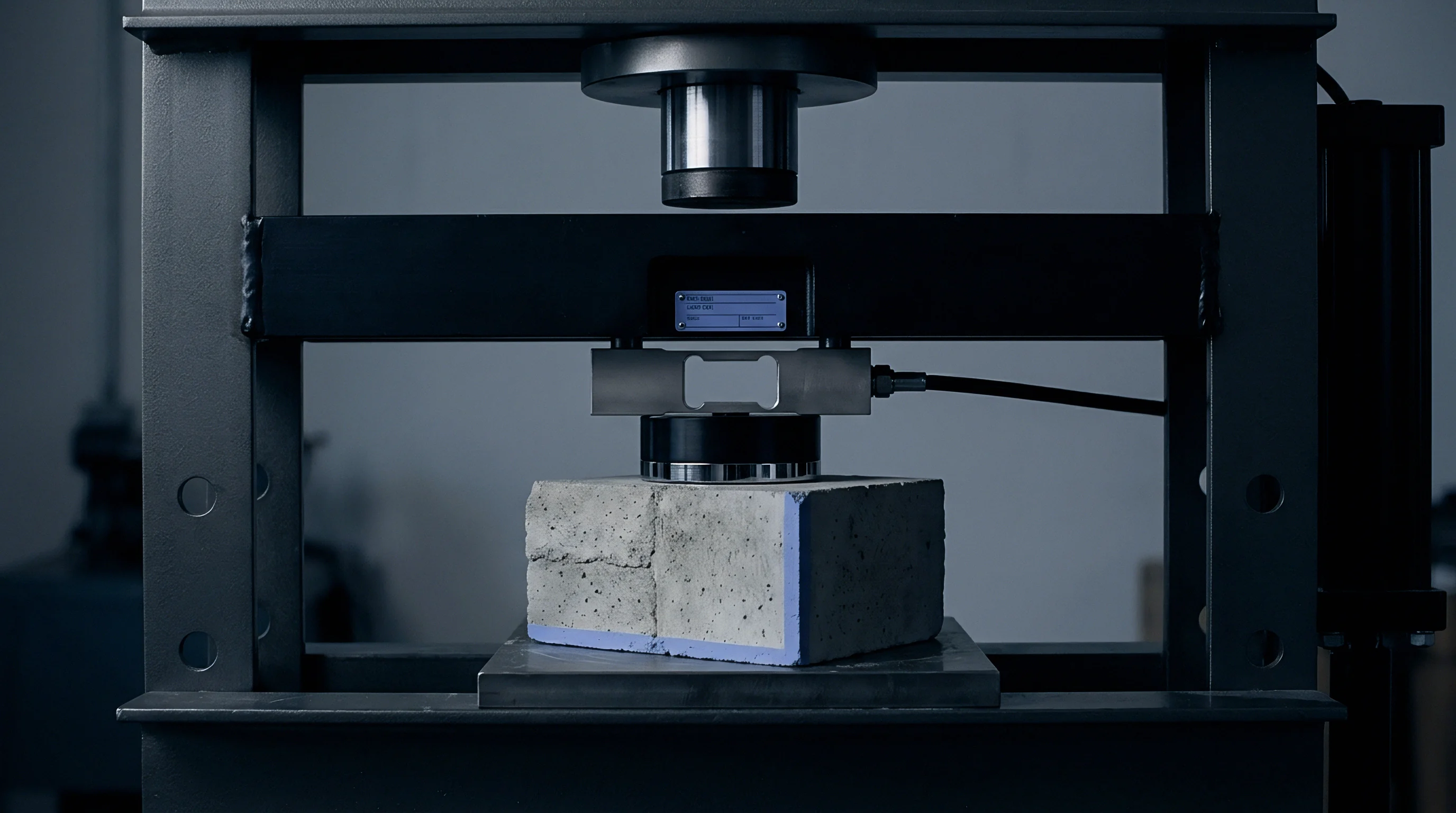
Inductive Transients across High Power Spindles
Variable frequency drive outputs push rapid current changes into unshielded motor conductors. These high current rate-of-change events create localized magnetic pulses that couple directly into parallel control conductors. When signal cables share tray space with motor leads, inductive coupling transfers high-voltage spikes onto signal lines.
Standard shield braids provide partial protection against radiated electric fields, but low-frequency magnetic coupling penetrates standard aluminum foil wraps.
Cell layout dictates electromagnetic field exposure levels across communication conduits. High-density machining cells position drive cabinets within two meters of high-speed data trunks. Unshielded machine tool enclosures allow stray flux to sweep across exposed fieldbus wiring during heavy cutting passes, resulting in noise bursts that disrupt bit edge detection inside industrial Ethernet transceivers.
Inductive energy couples into conductor loops running parallel to variable frequency drive cabling.
Cable construction directly influences immunity against ambient industrial noise. Twisted-pair geometry cancels differential-mode magnetic coupling as long as pitch consistency remains uniform along the run. Double-shielded cables featuring both braided tinned copper and foil wrapping yield higher attenuation factors than single-foil alternatives.
Mechanical strain during machine axis motion degrades shield integrity over time, where broken shield strands increase ground loop impedance and diminish high-frequency attenuation performance across the channel.
- Capacitive Crosstalk High voltage rate-of-change pulses on power leads transfer charge across air gaps into adjacent unshielded signal wires.
- Common-Mode Flux Magnetic fields surrounding motor cables induce identical voltage spikes on both conductors of a signal pair.
- Ground Potential Drift Heavy spindle current returns create potential differences between distant ground points in the machining cell.
- Radiated Impulse Bursts Arc events from mechanical contactors radiate broadband radio frequency energy across unshielded enclosures.
Placing signal lines within twelve inches of unshielded spindle leads forces system dropouts that interrupt production shifts.


Distortion
Physical signals on continuous industrial Ethernet lines degrade when spatial magnetic fields induce differential noise. Real-time deterministic fieldbus protocols like EtherCAT and PROFINET Isochronous Real-Time rely on exact pulse edge arrival times to calculate clock offsets across distributed nodes. High electromagnetic noise shifts signal transition thresholds at the physical layer transceiver.
This shift shows up as phase jitter, altering the perceived pulse width of incoming data frames until receiver phase-locked loops struggle to track rapid phase variations, leading to sampling errors during frame preamble reception.

Phase Variance in Physical Layer Transceivers
Clock recovery circuits inside physical interface chips rely on sharp differential transition edges to maintain synchronization. Stray electromagnetic fields distort pulse rise and fall times, blurring the distinction between high and low logic states. When differential noise voltage exceeds receiver hysteresis levels, signal transition points drift relative to the master clock.
Bit timing jitter expands beyond permitted protocol tolerances, causing frame check sequence failures that degrade network determinism through frame retries.
Accumulated jitter reduces maximum usable cycle rates in motion control networks. A system configured for a two-hundred-fifty microsecond cycle budget tolerates less than one microsecond of peak-to-peak phase jitter before synchronization flags trigger. When electromagnetic interference drives jitter past this boundary, drive controllers miss motion updates and enter a fault condition, bringing multi-spindle machining operations to a stop while resetting the transmitter.
| Protocol Type | Nominal Cycle Time | Max Permitted Jitter | Physical Layer Standard | Bit Error Rate Threshold |
|---|---|---|---|---|
| EtherCAT | 125 µs | ±100 ns | 100BASE-TX (IEEE 802.3) | 10 to the power of -12 |
| PROFINET IRT | 250 µs | ±1 µs | 100BASE-TX (IEEE 802.3) | 10 to the power of -10 |
| TSN (IEEE 802.1Qbv) | 500 µs | ±500 ns | 1000BASE-T (IEEE 802.3ab) | 10 to the power of -12 |
| CANopen | 10 ms | ±5 µs | ISO 11898-2 | 10 to the power of -9 |
High electromagnetic interference alters bit symmetry within physical interface drivers. Cable attenuation combined with noise-induced edge rounding compresses the eye pattern opening observed on high-speed lines. Reduced eye height lowers noise margins, making the data stream susceptible to random thermal noise.
Systematic edge shifts cause fixed phase offsets in node synchronization logic, allowing phase drift to accumulate across daisy-chained topology nodes over consecutive communication cycles.
Disagreements often arise over whether communication dropouts stem from improper software configuration or physical layer signal corruption.


Topology
Structural cable routing paths dictate how effectively plant electrical noise couples into signal pathways. Shared machining cells feature dense metal framing, continuous ground grids, and localized cable trays carrying power and data. Physical separation between power conductors and signal conduits acts as the primary barrier against inductive noise transfer.
Routing deterministic bus lines through dedicated metallic conduit provides continuous electromagnetic shielding across cell boundaries, grounding transient currents to keep high-frequency flux from reaching internal signal conductors.
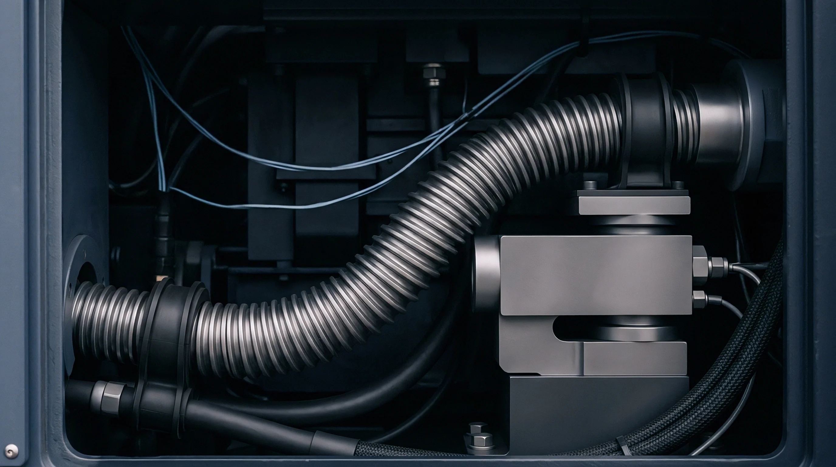
Equipotential Bonding and Conduits
Grounding conductors run alongside high-speed data cables to equalize voltage differentials across machine frames. Machine tool bases experience significant ground voltage fluctuations during spindle acceleration cycles. Without low-impedance equipotential bonding, stray current flows through data cable shields between adjacent machine frames, where ground loop currents saturate the shields and destroy their capacity to attenuate high-frequency external fields.
Integrators manage cable routing through disciplined infrastructure auditing.
- Integrate 360-degree shield clamps at all cabinet entry plates to ensure full metallic contact with the enclosure backplane.
- Measure ground loop impedance across adjacent machine frame segments using a dedicated high-frequency milliohm meter.
- Verify channel attenuation and cable return loss using a calibrated Category 6A cable analyzer prior to production commissioning.
- Run stress sweeps while cycling all cell variable frequency drives across their complete operational speed range.
IEC 61000-4-4 Level 4 mandates burst immunity testing at four kilovolts on I/O ports to qualify real-time fieldbus hardware.
Industrial Ethernet connectors require physical protection against environmental and electrical degradation. Threaded M12 X-coded connectors maintain continuous 360-degree shield contact through metal housing threads, outperforming standard RJ45 connectors in high-vibration machining environments. Unshielded connector shells introduce impedance discontinuities that reflect high-frequency signal components, which combine with external noise to compound phase jitter inside fieldbus interface modules.
Standard IEC 61800-3 category C2 defines maximum allowed radiation levels, altering mandatory installation geometry for all cell network runs.

Budget
Real-time motion networks allocate strict cycle windows for frame transmission and processing. High-speed CNC machining requires deterministic updates to maintain interpolated multi-axis toolpaths without contouring errors. Jitter consumes available delay margins inside the network cycle frame.
When electromagnetic interference delays edge transitions, the receiving node spends extra time validating incoming data frames, and because cyclic execution schedules rely on predictable packet arrival, unexpected propagation delays force processing tasks into subsequent clock cycles.

Can Transient Burst Tests Predict Packet Loss Rates?
Standard laboratory burst generators simulate fast electrical surges on signal lines, applying high-voltage pulse packages to evaluate transceiver hardware robustness. Laboratory bursts deliver repeatable noise patterns, but machine tool cells create unpredictable interference spectra during tool contact and spindle reversal. Field trials show higher packet drop rates during real machining operations than predicted by basic laboratory burst testing.
Real-time network timing budgets divide total available cycle time into distinct transmission phases. Isochronous real-time data frames occupy fixed timing slots, followed by asynchronous user data and diagnostic traffic.
Electromagnetic interference forces data corruptions that trigger automatic frame retransmissions during non-isochronous windows. Frame retries consume bandwidth allocated for background diagnostics, leading to buffer overflows inside switch fabrics.
Phase jitter exceeding twenty percent of nominal bit duration causes unrecoverable synchronization failure in motion controllers.
Distributed clock synchronization protocols like IEEE 1588 PTP rely on precise timestamp exchange between master and slave nodes. EMI-induced phase jitter corrupts egress and ingress timestamping logic at Ethernet physical layer ports. Incorrect timestamps yield inaccurate propagation delay calculations across network segments.
Slave clocks drift from the master reference, introducing timing skew across independent CNC axis controllers that ultimately causes subtle surface finish flaws on machined parts.
Cable routing separation yields better timing stability than software retry algorithms.


Oscilloscope
High-bandwidth voltage capture instruments reveal high-speed signal integrity breakdown in production cells. Measuring deterministic bus jitter under actual machining loads requires digital storage oscilloscopes featuring minimum real-time sampling rates of four gigasamples per second. Active differential probes connect directly to physical layer differential pairs without loading the communication line.
Deep memory buffers capture full motor acceleration profiles, allowing engineers to correlate transient electromagnetic surges with specific bit pattern distortions.

Eye Diagram Metrics under Peak Load
Signal transition overlays display timing jitter and amplitude noise simultaneously. Connecting scope channels to differential transmit lines generates eye diagrams that capture cumulative signal degradation. Under zero-load conditions, the eye pattern presents clean, sharp boundaries with wide vertical openings and narrow horizontal crossover points.
Operating all cell spindles at maximum torque narrows the eye opening significantly, while time-domain reflectometry pinpoints exact impedance changes along damaged cable segments where reflections corrupt pulse shapes.
Evaluating jitter requires quantitative separation of random jitter components from deterministic jitter components. Random jitter follows a Gaussian distribution driven by thermal noise within transceiver semiconductors, whereas deterministic jitter exhibits bounded peaks caused by power supply ripple, cross-talk, and periodic VFD switching bursts. Fast Fourier Transform mathematical functions inside modern scopes isolate spectral peaks corresponding to specific drive switching frequencies, pinpointing the root source of fieldbus degradation.
| Routing Infrastructure | Separation Distance | Peak-to-Peak Jitter | Frame Error Rate | Eye Height Opening |
|---|---|---|---|---|
| Open Plastic Cable Tray | 0 cm (Parallel Run) | 480 ns | 3.4 times 10 to the power of -3 | 120 mV |
| Unshielded Wire Mesh Tray | 10 cm | 185 ns | 1.2 times 10 to the power of -5 | 280 mV |
| Continuous Steel Conduit | 30 cm | 18 ns | 1.0 times 10 to the power of -9 | 610 mV |
| Separated Heavy Wall Conduit | 50 cm | 4 ns | less than 10 to the power of -12 | 740 mV |
Consider a five-axis machining cell operating four 45-kilowatt spindles fed by individual variable frequency drives. Industrial Ethernet cabling runs through a shared wire mesh tray for a distance of twenty-five meters. At nominal idle spindle speeds, measured bus phase jitter averages twelve nanoseconds peak-to-peak.
Applying heavy roughing cuts causes drive switching currents to rise rapidly, generating localized broad-band electromagnetic field intensities reaching eight volts per meter at the signal tray, where high spatial fields collapse physical layer noise margins.
Under these heavy cutting conditions, measured peak-to-peak phase jitter expands to three-hundred-twenty nanoseconds. The network operates on a two-hundred-fifty microsecond EtherCAT cycle with an allowable sync jitter margin of plus or minus one hundred nanoseconds. Expanded jitter exceeds node phase-locked loop tracking capabilities, driving node synchronization error flags high.
The network controller registers twenty-four corrupted frames per minute, exceeding acceptable real-time operational parameters unless ferrite cores are added to damp transients.
A fifty-nanosecond phase variance under peak electromagnetic pulse conditions increases frame retry rates by three orders of magnitude.
Continuous monitoring tools offer real-time tracking of network health parameters without interrupting production processes. Diagnostic switches capture frame error counters, crc failures, and alignment errors directly from physical layer registers. Mapping these error counts against machine execution logs confirms the link between heavy cutting passes and fieldbus signal degradation.
Engineering teams utilize these logged metrics to qualify machine cell readiness prior to committing high-volume production orders.
Whether transient phase variance under multi-axis machining peak load can be modelled analytically remains an open question for cell integrators.


Remedy
Hardening deterministic networks against electromagnetic interference requires targeted structural interventions. Replacing copper physical layer infrastructure with industrial fiber optic cables eliminates electromagnetic noise coupling across data links. Fiber optic lines transmit data via photonics, rendering communication channels immune to high-voltage transients, ground potential variations, and magnetic flux sweep events.
Optical media converters convert electrical signals to light at cabinet boundaries, isolating vulnerable fieldbus trunks from cell noise sources.

Optical Isolation and Active Suppression
Photonic media completely block electromagnetic induction across data paths. Converting long cable runs between machining cells to plastic optical fiber or glass optical fiber isolates communication circuits from heavy ground loops. Where copper cabling must remain due to legacy device constraints, active transient absorption filters damp high-frequency noise spikes before signals enter sensitive physical layer chips, preserving differential pulse shapes under heavy cell interference.
Engineering teams execute systematic readiness updates using verified stage-gate criteria.
- Conduit Isolation Segregate high-speed deterministic bus cables into dedicated continuous steel conduits separated from power leads by fifty centimeters minimum.
- Bonding Audit Install low-impedance copper bonding straps across all cabinet sub-panels to maintain uniform ground potential across machine frames.
- Connector Hardening Replace standard RJ45 field terminations with IP67-rated metal M12 X-coded connectors featuring full circumference shield clamping.
- Active Monitoring Deploy managed Ethernet switches equipped with hardware-based packet timing analysis tools to log real-time jitter dynamics.
Capital expenditure allocated for physical layer hardening yields quantifiable improvements in machine cell uptime. Upgrading network infrastructure prevents random cycle timeouts, stabilizing cycle performance across multi-spindle machining operations. Upstream layout decisions dictate long-term cell reliability.
Engineers finalize the cell wiring sign-off after three consecutive shifts run without a single cycle timeout.