Machining Cell Auxiliary Utility Capacity Baseline Audit Protocol
Dynamic auxiliary utility baseline audits prevent cell line trips by verifying instantaneous transient peak headroom rather than nominal nameplate ratings.

Draw
A four-axis machining cell running titanium aerospace bulkheads drops into feed hold at 14:22 on a Tuesday because the pneumatic line pressure drops below 5.2 bar during a secondary tool-change sequence. The supervisory control records a tool unclamping fault. Maintenance personnel replace the proximity switch on the spindle drawbar.
The machine repeats the failure three hours later when three adjacent vertical machining centres index their auxiliary rotary tables while the vacuum chip-evacuation cycle engages simultaneously. The spindle did not fail. The supply drops because the plant air distribution main falls below the minimum operating envelope required to overcome the tool unclamp piston return spring.
Auxiliary utilities define the physical floor beneath every machine tool specification sheet. When a plant expansion adds machining centres to an existing bay, engineering calculations frequently tally nameplate ratings from machine manufacturer utility plates, summing continuous kilowatt ratings, average volumetric compressed air demands, and nominal chilled water delivery rates. This arithmetic ignores dynamic coincident peaks, seasonal cooling water thermal saturation, pneumatic header pressure wave dynamics, and local voltage sags induced by cyclic servo acceleration.
True cell readiness demands an empirical, instrumentation-driven baseline audit protocol that maps utility capacity against transient demand envelopes rather than steady-state nameplate values.
Auxiliary utility systems encompass four primary physical vectors: compressed air delivery, process cooling water and dielectric fluid heat transfer, electrical power quality, and chip-swarf removal hydraulics or pneumatic vacuum transport. Every vector exhibits a distinctive transient response time. A factory air compressor requires thirty to ninety seconds to load fully from an idle state; a machine tool pneumatic tool changer expends 45 normal litres of air in 800 milliseconds.
The mismatch between supply response latency and demand impulse duration produces localized starved conditions that trigger false alarms, shorten cutting tool life through intermittent through-spindle coolant starvation, and generate dimensional drift across precision part families.
A machine tool utility plate records nominal consumption during steady-state cut cycles rather than the transient load spikes that destabilize shared factory distribution headers.
Executing an auxiliary utility capacity baseline audit protocol establishes the exact operating margin between dynamic demand peaks and actual delivery capacity at the cell drop point. The protocol decouples cell installation from plant-level utility assumptions, forcing a rigorous verification sequence prior to signing commercial equipment acceptance certificates. Capital commitments made without continuous high-frequency baseline utility records risk systemic production rate suppression, high scrap rates during shift overlap periods, and perpetual disputes between machine tool builders and plant facility engineers.
The failure to audit utility capacity prior to capital commitment forces operations to run cells at de-rated feeds and speeds, directly destroying the internal rate of return projected in the original equipment justification.


Plenum
Pneumatic supply lines behave as compressible fluid networks subject to friction loss, inertial resistance, and storage volume limitations. Machining cells consume compressed air in two distinct regimes: continuous low-demand consumption for spindle purge seals, linear scale positive-pressure enclosures, and optical encoder shields; and high-demand, short-duration transients for tool changes, chip clearing air blasts, part seating confirmation sensors, and pallet clamping mechanisms. A 5-axis horizontal machining centre typically consumes 120 normal litres per minute continuously at 6 bar for bearing contamination exclusion.
During an automated pallet exchange and dual tool changer cycle, instantaneous air demand surges to 1,800 normal litres per minute for a duration of 2.4 seconds.
Supply pipe sizing conventions based solely on continuous demand generate catastrophic pressure drops across these cycles. The terminal branch connection, often routed via flexible hose or undersized galvanized drop legs from an overhead header, acts as a flow restrictor. Under transient draw, the pressure wave propagates upstream at the local speed of sound in air, approximately 343 metres per second.
If the local storage capacity within three pipe metres of the machine regulator is insufficient, downstream pressure collapses below the threshold of the machine internal safety pressure switches, which are typically factory set to trip between 5.0 and 5.5 bar.
Pneumatic Baseline Measurement Rig Architecture
High-frequency data logging requires dedicated instrumentation installed directly at the final isolation ball valve of the machining cell drop. The standard facility pressure gauge mounted on an overhead manifold provides zero insight into dynamic transients; its mechanical needle dampening conceals oscillations lasting under two seconds. The audit protocol installs a high-speed piezoelectric or piezoresistive pressure transmitter paired with a thermal mass flow meter, logging at a minimum sample frequency of 100 Hertz.
- Differential pressure transmitters placed across point-of-use particulate and coalescing oil filters capture dynamic filter blinding under peak velocity conditions.
- Thermal mass flow meters installed upstream of the local cell regulator record true instantaneous consumption profiles across all standardized machining sequence steps.
- Point-of-use pressure dew point sensors verify that moisture content conforms to ISO 8573-1 Class 4 or higher during sustained, un-cycled maximum airflow phases.
- High-speed multi-channel data acquisition units synchronize pressure and flow signatures with machine numerical control status bits to isolate which specific programmed cycle step triggers hydraulic starvation.
Evaluating the resulting pressure curves reveals whether a cell deficit stems from insufficient compressor capacity or distribution pipe restriction. A steady, gradual pressure decay across all cells during a production shift points directly to bulk compressor plant inadequacy or desiccant dryer regeneration bypass losses. Conversely, a rapid, steep pressure drop confined to an individual machine cycle followed by an immediate recovery within two seconds indicates terminal pipe constriction or the absence of a point-of-use pneumatic accumulator reservoir.
Dynamic pneumatic pressure decay exceeding 0.8 bar during an automated tool changer stroke indicates inadequate local receiver capacity regardless of header line pressure.
Integrating a local pneumatic accumulator tank resolves transient pressure drops by providing instantaneous localized energy storage. The required receiver volume correlates directly with peak transient duration, allowable pressure dip, and upstream header replenishment flow. Calculating this volume prevents capital outlay on centralized plant compressors when the physical constraint is localized line impedance.
| Subsystem Mechanism | Duration (sec) | Base Flow (Nl/min) | Peak Flow (Nl/min) | Allowable Pressure Dip (bar) |
|---|---|---|---|---|
| Spindle labyrinth air purge | Continuous | 120 | 130 | 0.2 |
| Linear scale positive air purge | Continuous | 45 | 50 | 0.1 |
| Tool change taper blow-off | 1.8 | 0 | 1,450 | 0.6 |
| Spindle drawbar unclamp stroke | 0.8 | 0 | 1,800 | 0.5 |
| Pallet seat confirmation blast | 3.5 | 0 | 950 | 0.4 |
| Enclosure chip wash air sweep | 12.0 | 0 | 2,100 | 0.8 |
A compressed air distribution main sized strictly to nominal velocity standards of 6 metres per second fails when simultaneous tool changes produce local air velocities above 25 metres per second, producing severe turbulence and transient pressure throttling at elbows.
Coolant
Thermal stability governs metal-cutting precision. Modern high-speed machining cells generate immense thermal loads concentrated within the cutting interface, high-pressure through-spindle coolant delivery pumps, and direct-drive liquid-cooled motor spindles. Auxiliary cooling infrastructure operates across two primary domains: central or dedicated chilling circuits supplying closed-loop spindle jacket cooling, and process metalworking fluid systems providing chip evacuation, lubrication, and cutting zone temperature suppression.
Chilled water loops intended for spindle cooling and electrical enclosure heat exchangers require strict adherence to temperature and flow thresholds. Direct-drive spindles transferring 30 to 60 kilowatts of continuous shaft power lose approximately 8 to 12 percent of that electrical energy as heat rejected into the spindle housing jacket. If the process chiller lacks thermal capacity, chilled water delivery temperatures fluctuate.
A chilled water temperature deviation of 2 degrees Celsius shifts the structural spindle thermal equilibrium, causing axial drift of 8 to 18 micrometres along the Z-axis in standard mineral-casting or cast-iron column structures.

Hydraulic and Thermal Boundary Logging
Process fluid audit methods require non-invasive transit-time ultrasonic flow measurement devices clamped to supply and return lines, paired with calibrated thermistors logging to four decimal places. Nameplate chiller capacity, typically quoted in kilowatts of refrigeration at an ambient temperature of 25 degrees Celsius, drops precipitously when factory ambient conditions reach 38 degrees Celsius during peak summer operations. Chiller performance baselines must evaluate cooling circuits under conditions of maximum ambient factory temperature combined with the machine running sustained high-torque roughing operations.
Through-spindle coolant systems introduce severe hydraulic transient demands. Modern variable-frequency-drive high-pressure coolant units cycle from zero to 70 bar within 400 milliseconds to deliver emulsion directly to the drill tip during deep-hole operations. If the filtration system, whether paper band, cyclonic separator, or backwashing drum filter, exhibits high restriction due to swarf loading, pump suction heads fall below the fluid vapour pressure.
Cavitation occurs instantly, destroying internal pump vanes, generating acoustic shockwaves, and introducing micro-bubbles into the coolant stream that sharply diminish thermal boundary heat transfer capacity at the tool edge.

Why Do Factory Coolant Headers Experience Flow Starvation?
Simultaneous activation of high-pressure coolant across multiple machining cells sharing a centralized distribution loop creates transient pressure nodes. Ultrasonic transit-time flow testing reveals that when Cell B initiates a 70 bar through-spindle cycle, the dynamic supply pressure in the shared header drops by 1.8 bar, reducing delivery flow to the external nozzle ring of Cell A by 28 percent. This hydraulic interaction produces premature flank wear on carbide end mills in Cell A, a defect routinely blamed on batch-to-batch tool coating inconsistencies rather than utility hydraulic architecture.
Total dissolved solids, tramp oil concentration, and water hardness directly influence fluid specific heat capacity and kinematic viscosity. Aqueous cutting fluid carrying 4 percent tramp oil concentration exhibits a measurable drop in specific heat capacity compared to virgin emulsion, degrading heat removal efficiency at high cutting speeds. The baseline utility audit captures both fluid mechanical flow parameters and fluid physical-chemical attributes, compiling a complete map of thermal dissipation capacity.
The machine tool builder rejects spindle warranty claims when internal chiller temperature logs prove the client ran incoming jacket coolant outside the specified 20 to 22 degrees Celsius operating band.

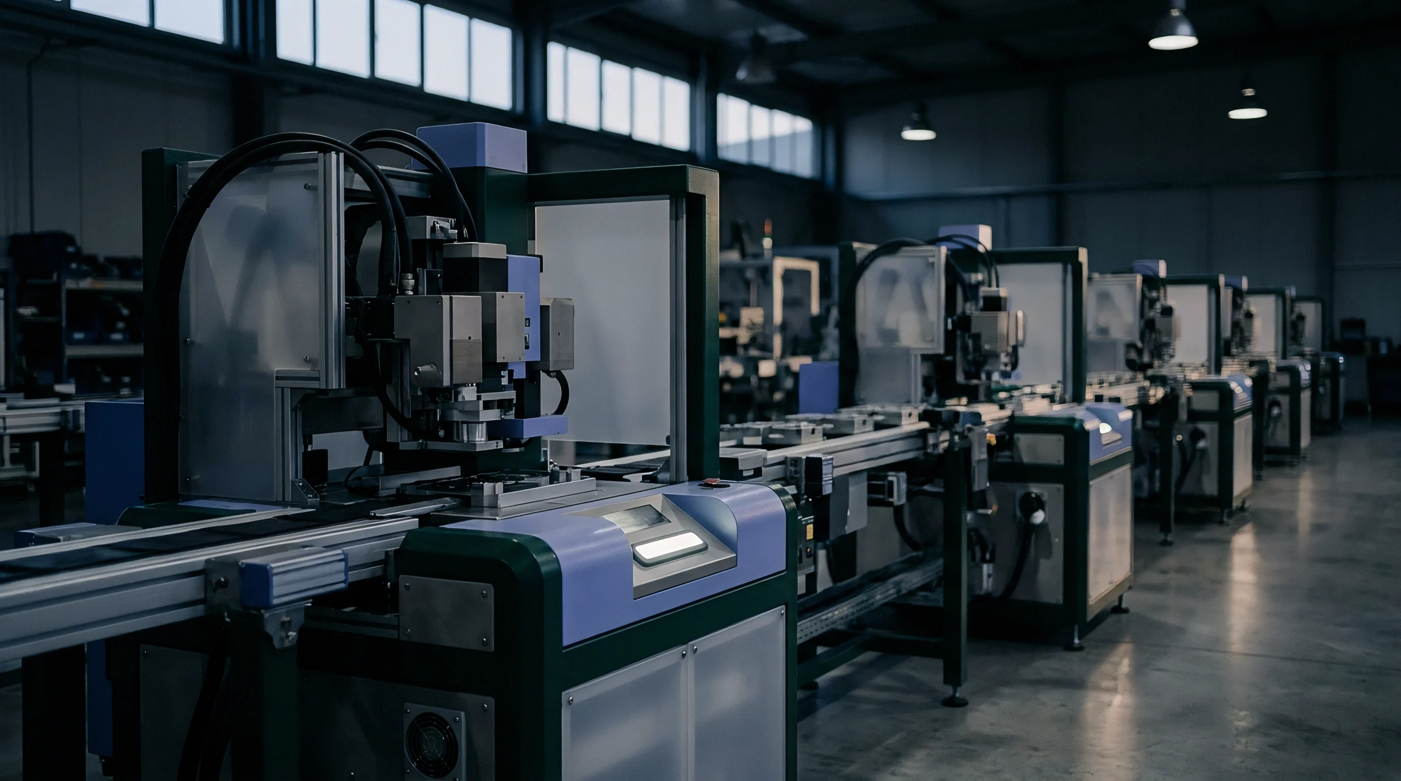
Grid
Machining cells impose harsh, highly dynamic non-linear loads on incoming low-voltage electrical distribution switchgear. Modern multi-axis computer numerical control machines utilize common DC-bus architectures linking regenerative spindle drives and multiple AC servo drives. While these setups allow braking energy from decelerating axes to power accelerating axes, aggressive acceleration profiles generate sharp peak current draws followed by harmonic injection into the plant branch supply.
Voltage drops, harmonic distortion, and phase unbalance represent the critical electrical vectors audited under this protocol. A class-A power quality analyzer must monitor the electrical cell drop for a continuous seven-day production cycle at a sampling rate compliant with IEC 61000-4-30 Class A standards. Spot-checking voltage with a standard digital multimeter is ineffective, as it records RMS voltage averaged over dozens of line cycles, concealing transient sags that last two to five cycles.

Voltage Sag and Peak Inrush Profile Analysis
Transient voltage sags occur when heavy induction motors start across the plant or when adjacent machining cells accelerate high-inertia rotary tables and heavy direct-drive spindles simultaneously. An instantaneous voltage sag below 90 percent of nominal voltage lasting longer than 20 milliseconds can force sensitive CNC axis power modules into undervoltage alarm condition, halting machining cycles and generating surface gouges on expensive workpieces. In installations where the upstream step-down transformer operates near its saturation threshold, total harmonic distortion of current (THDi) easily exceeds 15 percent, overheating distribution neutrals and causing power factor correction capacitor banks to trip offline.
- Step-down transformer capacity verification establishes that rated apparent power in kilovolt-amperes accounts for non-linear load crest factors exceeding 2.5 without core saturation.
- Sub-cycle voltage drop profiling correlates spindle ramp-up sequences against supply line voltage drop percentages to confirm supply cable cross-sectional area adequacy.
- Harmonic distortion spectrum mapping records voltage and current harmonics through the 50th order to identify resonance conditions near the switching frequencies of modern IGBT power converters.
- Phase voltage unbalance measurement confirms that phase-to-phase voltage differentials remain strictly below 1.5 percent under maximum unbalanced single-phase load configurations.
Phase unbalance represents a destructive, often neglected electrical defect. When three-phase supply voltages deviate by as little as 2.0 percent, induction motors and spindle chiller compressors experience internal phase current unbalances reaching 15 to 20 percent. This creates excessive localized I-squared-R winding heating, degrading motor insulation prematurely and tripping thermal overload relays during completely normal ambient operating conditions.
A phase voltage unbalance exceeding 2.0 percent at the machine disconnect switch induces motor winding temperature spikes that destroy spindle drive insulation.
Mitigating electrical baseline shortfalls requires precise sizing of isolation transformers and active power filtering units at the cell boundary. If the upstream network impedance is high, standard passive line reactors prove insufficient to suppress harmonic distortion and voltage notches, necessitating dedicated active front-end line conditioning units.
| Electrical Parameter | Target Operating Band | Warning Threshold | Critical Fault Trigger | Standard Reference |
|---|---|---|---|---|
| Voltage steady-state variation | Nominal ±3% | Nominal ±5% | Nominal ±10% | ANSI C84.1 Range A |
| Voltage sag maximum depth | 0% to 5% drop | 5% to 10% drop | Greater than 10% drop | SEMI F47-0706 Curve |
| Total harmonic distortion (THDv) | Under 3.0% | 3.0% to 5.0% | Greater than 8.0% | IEEE 519 Standard |
| Total demand distortion (TDD) | Under 5.0% | 5.0% to 8.0% | Greater than 12.0% | IEEE 519 Standard |
| Voltage unbalance factor | Under 1.0% | 1.0% to 1.5% | Greater than 2.0% | IEC 61000-2-4 Class 2 |
| Transient voltage spikes (peak) | Under 100V above peak | 100V to 300V above peak | Greater than 500V above peak | IEEE 1159 Practice |
The facility team insists the plant power supply is stable because the utility provider maintains substation transmission voltage within national legal tolerances.

Trench
Chip removal, swarf management, and centralized mist collection constitute the final mechanical boundary of machining cell infrastructure. High-volume metal removal, particularly roughing structural aluminium or nickel-chromium superalloys, produces voluminous chip masses that rapidly overwhelm internal machine enclosures if the extraction utilities fail to maintain continuous transport velocity. Swarf extraction utilities function either via localized machine-mounted drag flight conveyors, screw augers, or plant-wide centralized vacuum-pneumatic or flume trenches routed below the factory floor.
Swarf transport failure manifests as chip re-cutting, physical jamming of the pallet shuttle mechanism, and coolant basin overflow. In aluminium structural machining, volumetric chip generation rates can exceed 8,000 cubic centimetres per minute during sustained full-slot pocket roughing operations. When chip handling utilities suffer intermittent pauses or hydraulic flow reductions, chips accumulate around linear guide covers and optical scale purge seals.
The mechanical friction of accumulating hot chips transfers heat directly into the machine cast base, creating asymmetric structural thermal gradients that distort axis squareness.

Flume and Extraction Utility Audit Procedure
Auditing chip flume return systems requires measuring liquid velocity, flume geometry cross-sectional capacity, and particulate concentration gradients along the trench length. Central flume trenches rely on high-volume, low-pressure coolant flume flush pumps delivering liquid velocities between 1.5 and 2.5 metres per second to keep heavy steel or titanium chips in active suspension. If the flume flush delivery pressure decays due to line scaling or undersized piping, chip settlement occurs.
Settled chips form dams, causing coolant to back up into machine base discharge chutes and triggering high-level float switches that halt cutting cycles.
Centralized oil mist exhaust and vacuum collection utilities introduce an interrelated aerodynamic capacity balance. Machine enclosures operate under negative internal atmospheric pressure to prevent aerosolized coolant and hazardous polycyclic aromatic hydrocarbon mists from escaping into the operator breathing zone. If mist extraction duct velocity falls below 15 metres per second, aerosol droplets condense inside horizontal duct runs, pooling hundreds of kilograms of liquid inside overhead suspended sheet metal systems, posing structural hazards and drastically reducing air extraction volume at the machine enclosure interface.
Air extraction duct velocities below 15 metres per second cause aerosolized coolant condensation to pool liquid in suspended overhead lines, choking enclosure exhaust airflow.
A complete baseline audit measures static suction pressure at each machine enclosure exhaust port using differential pressure manometers, confirming that static negative pressure remains between negative 50 and negative 150 Pascals with enclosure doors closed and internal coolant delivery running at full operating pressure. Airflow volumes must be quantified with multi-point pitot tube traverses conducted in accordance with ANSI/AMCA 203 standards across all cell duct takeoff points.
The facility cannot deploy the planned high-speed roughing tools until the sub-floor flume trench liquid velocity is restored to levels capable of preventing chip dam formation.


Protocol
Synthesizing auxiliary utility verification into an operational readiness gate demands an audit protocol executed across a mandatory three-phase chronological timeline. The protocol links engineering parameters to commercial stage gates, preventing final equipment sign-off until the machining cell demonstrates complete utility dynamic stability under maximum stress conditions. Skipping baseline verification steps guarantees that latent facility bottlenecks will surface as catastrophic downtime during production ramp-up.

Phase One: Static Physical Capacity Audit
Conducted prior to machine tool arrival, this phase surveys the physical infrastructure of the bay. Physical pipe inner diameters, electrical cable conductor gauges, disconnect switch fuse ratings, step-down transformer tap positions, and facility header layouts undergo engineering audit against peak cell consumption documentation. Inspectors must verify that the pneumatic line feeding the cell drop connects to the top of the main overhead distribution loop rather than the bottom, preventing accumulated condensed moisture from entering the machine drops during production line idle periods.

Phase Two: Dynamic Isolated Stress Audit
Executed once the machine tool is powered and mechanically commissioned, this phase isolates the cell from adjacent production interference. The cell executes its maximum demanding operational sequence continuously for 24 hours. This sequence includes simultaneous through-spindle coolant running at 70 bar, rapid five-axis interpolation with maximum acceleration vectors, dry-run tool change cycles at maximum speed, and enclosure wash-down systems running concurrently.
Dedicated high-frequency data loggers monitor pneumatic pressure dip, electrical total harmonic distortion, phase voltage drop, chilled water supply delta-temperature, and vacuum exhaust suction. If any utility parameter crosses the warning thresholds established in the engineering baseline matrix, the audit halts. Machine operation cannot receive stage-gate sign-off based on promises of future facility improvements; root causes are resolved on the infrastructure side immediately.

Phase Three: Concurrent Multi-Cell Coincidence Audit
The final phase tests the shared utility distribution network under maximum coincidence factor conditions. All machining cells sharing the overhead pneumatic header, cooling water chiller loop, electrical substation bus, and centralized chip flume execute their peak transient cycles simultaneously. This phase replicates the most severe operating scenario: the moment following a shift change when all operators initiate cycle starts within the same five-minute window.
- Pneumatic transient stress trigger commands simultaneous automated tool changer sweeps across every cell connected to the common distribution manifold to record minimum dynamic pressure drop.
- Electrical bus inrush synchronization aligns rapid spindle acceleration cycles to 15,000 RPM across all spindle drives, logging instantaneous voltage sag depth at the secondary distribution board.
- Thermal saturation cycle execution runs maximum continuous metal removal cutting cycles across all machines for four hours, measuring chiller return temperatures to verify thermal dissipation margins under peak heat load.
- Hydraulic flume capacity validation floods the chip trench with maximum chip volume roughing passes, verifying continuous fluid velocities without chip settlement or machine base coolant back-up.
Documenting these empirical results yields an auditable utility baseline dossier. This dossier establishes an unassailable baseline of facility delivery capacity. When future operational bottlenecks arise, operations management references this baseline to instantly determine whether a throughput shortfall stems from internal machine component degradation or unauthorized utility load additions to the shared infrastructure.
According to Section 4.2 of the standard machine procurement contract, failure to document incoming utility compliance invalidates the machine tool manufacturer warranty for linear motor thermal distortion and spindle failure.

Margin
Calculating the true auxiliary utility capacity margin requires rigorous engineering arithmetic applied to coincident transient events rather than simple algebraic subtraction of steady-state averages. A rigorous audit protocol constructs a dynamic headroom ratio for each utility vector, expressing the mathematically defined distance between peak transient cell demand and the minimum delivery threshold of the facility supply network. This arithmetic serves as the objective gate for scaling decisions: if the headroom ratio drops below 1.25, the cell possesses inadequate resilience to withstand normal manufacturing process drift.
Consider an operational scenario where a manufacturing expansion plans to integrate three identical 5-axis horizontal machining centres into an existing production bay. The current plant infrastructure delivers compressed air via an 80-millimetre overhead loop maintained at 7.0 bar gauge by two oil-free rotary screw compressors delivering 14.0 normal cubic metres per minute total. Current plant continuous baseline demand stands at 10.5 normal cubic metres per minute.
A standard facility review concludes that 3.5 normal cubic metres per minute of surplus capacity remains, comfortably exceeding the combined nameplate consumption of the three new cells, which totals 1.8 normal cubic metres per minute.
This steady-state arithmetic hides an operational failure. Each new cell executes a high-speed twin-arm tool changer sequence requiring 1,800 normal litres per minute for 1.2 seconds, occurring every 45 seconds during cycle times. The worst-case operational scenario occurs when all three machines execute a tool change within a two-second window, demanding a combined transient air rate of 5,400 normal litres per minute.
The total instantaneous demand surges to 15.9 normal cubic metres per minute, instantly exceeding the maximum delivery output of the compressor plant. The line pressure at the drops will decay below the critical 5.2 bar threshold within 1.1 seconds unless local accumulator storage is provided.
The necessary point-of-use pneumatic accumulator storage volume is calculated using the standard compressible gas storage relationship:
V = (Q_peak – Q_supply) t / (P_initial – P_final)
In this expression, V represents the local storage volume in cubic metres; Q_peak represents the total transient consumption rate in standard cubic metres per second; Q_supply represents the available supply flow through the drop leg in standard cubic metres per second; t represents the duration of the transient event in seconds; P_initial represents the minimum line pressure before the event in bar absolute; and P_final represents the minimum allowable terminal pressure at the machine regulator inlet in bar absolute.
Assuming a supply line replenishment rate through the drop leg restricted to 400 normal litres per minute (0.00667 standard cubic metres per second) due to pipe friction, a transient demand of 1,800 normal litres per minute (0.030 standard cubic metres per second) for 1.2 seconds, an initial pressure of 6.8 bar absolute, and an allowable final minimum pressure of 5.8 bar absolute, the required local accumulator volume per machine is:
V = (0.030 – 0.00667) 1.2 / (6.8 – 5.8) = 0.028 cubic metres, or exactly 28 litres.
Installing a standard 50-litre local pressure receiver directly at the drop leg of each machining cell decouples the transient tool change demand from the overhead distribution header. The local receiver supplies the instantaneous volume without drawing down header pressure, maintaining line stability across the entire manufacturing bay. The identical arithmetic must be applied across electrical kVA demand, chiller thermal absorption rates, and flume hydraulic volume capacities.
Whether facility engineering budgets will allocate capital for localized auxiliary utility accumulators prior to machine delivery remains the subject of ongoing corporate negotiation.