Thermal Drift Control Principles in High Precision Continuous Machining Operations
Active fluid chilling and real-time algorithmic compensation control structural thermal drift to preserve process capability in continuous precision machining.
Swell
A continuous milling spindle running at fifteen thousand revolutions per minute pushes heat directly into the machine column through bearing friction and motor stator losses. Machining centers holding five-micrometer part tolerances face immediate tool center point deviation when operating across an uninterrupted eight-hour shift. The cutting edge moves outward as cartridge heat expands the rotating shaft.
The spindle grows. This axial lengthening accounts for sixty to seventy percent of total volumetric tool placement error during roughing and finishing transitions. When operators adjust coordinate work offsets at the start of a production run, that baseline vanishes within forty minutes of steady spindle operation as internal components warm toward steady-state equilibrium.
Heat migrates into the casting. Toolholder shank taper geometry alters under thermal expansion, creating radial runout that degrades surface finish on optical and aerospace surfaces. High-speed spindle packages generate between eight hundred and two thousand watts of thermal energy within a concentrated volume of the front bearing cluster.
Angular contact ceramic bearings reduce friction generation relative to steel alternatives, yet preload pressure under heavy continuous side-loads accelerates local heat generation. The front spindle nose migrates forward along the Z-axis while angular tilt develops if the mounting flange experiences asymmetric heat dissipation into the headstock housing.
Spindle Growth under Continuous Cut
Cartridge housings subjected to steady rotational velocity expand unevenly around the circumferential coolant jacket. The rotating assembly reaches an internal temperature between thirty-eight and forty-five degrees Celsius under continuous duty cycles, while the outer housing remains near ambient shop conditions. This internal-to-external thermal differential creates localized stress and tilts the tool center point along the Y-axis.
Machining stops when offsets diverge. The Z-axis elongation frequently exceeds twenty-five micrometers during the initial ninety minutes of machining before stabilizing, creating step errors on face-milled datum planes.
Cooling oil delivered to high-speed cartridge bearings at two degrees below ambient bed temperature holds axial tool elongation under four micrometers.
Structural Loop Displacement Mechanics
Cast iron bases, columns, and slide tables form a closed kinematic chain linking the cutting tip to the secured workpiece fixture. Heat entering this mechanical loop originates from cutting action, axis drive motors, linear guideway friction, and ambient room air currents. Each metallic element within the loop expands according to its linear coefficient of thermal expansion, which ranges from ten to twelve micrometers per meter per degree Celsius for typical pearlitic cast iron.
A temperature change of merely two degrees across an eight-hundred-millimeter cast column displaces the horizontal spindle position by sixteen micrometers. Thermal error dominates geometric error. The structural loop twists as thermal gradients traverse asymmetric ribs inside the machine column, rotating the tool axis away from the intended perpendicularity relative to the pallet face.
| Component Assembly | Material Grade | Expansion Coefficient (µm/m·K) | Heat Source Type | Mean Temperature Rise (K) | Resulting Displacement (µm) |
|---|---|---|---|---|---|
| Spindle Rotor Shaft | Alloy Steel 4340 | 12.3 | Bearing and Stator Losses | 14.5 | 26.8 |
| Vertical Column | Cast Iron FC300 | 10.8 | Ambient Drafts and Motor Conduction | 2.8 | 18.1 |
| X-Axis Ball Screw | Induction Hardened Steel | 11.7 | Nut Preload and Bearing Friction | 6.2 | 21.7 |
| Workpiece Pallet | Ductile Iron FCD600 | 11.2 | Coolant Splash and Swarf Accumulation | 3.4 | 7.6 |
| Toolholder Interface | Tool Steel H13 | 10.4 | Primary Shear Zone Heat Flow | 18.0 | 9.3 |
Workpiece fixtures absorb radiant and conductive heat from accumulated metal chips resting in the enclosure trough. Piling hot aluminum or titanium turnings against the machine table creates localized thermal pockets that distort the reference locating pins. When production runs proceed across second and third shifts without periodic swarf evacuation, the bottom datum of the fixture expands laterally, causing part bore locations to drift outside drawing limits.
Ignoring structural loop thermal growth produces out-of-tolerance bore diameters and steps across face-milled planes that scrap expensive workpieces during multi-axis machining operations.
Gradient
Horizontal temperature variations across machine foundations generate bending moments that bow linear guideways. Plant concrete slabs act as thermal reservoirs, absorbing solar radiation during midday through exterior walls and cooling through perimeter footings at night. An air temperature difference of three degrees Celsius between floor level and crane height induces a progressive vertical heat slope across five-axis gantry machines.
Cast iron absorbs energy slowly. The top crossbeam expands at a faster rate than the floor-anchored bed, causing the vertical columns to splay outward and misaligning the dual synchronized drive motors.
Spatial Temperature Fields in Machine Beds
Internal stiffening ribs cast into heavy machine bases restrict free thermal movement, turning linear expansion into physical distortion. As heat from hydraulic sumps or chip conveyers conducts into one side of a bed casting, that side lengthens while the opposite side remains rigid. The guideway reference surfaces bow into a convex curve.
A bed curvature of three micrometers over two meters produces an angular pitch error at the tool tip that translates to a ten-micrometer position error across the workpiece boundary.
Coolant collecting in base troughs creates erratic temperature distributions along the underside of axis ways. Cutting fluid delivered at shop ambient temperature warms as it washes over hot workpieces and chips, returning to the machine base at elevated temperatures. The fluid warms the casting locally before draining into the main filtration tank.
This uneven wash cycle sets up transient thermal patterns that shift continuously as cutting depth and chip generation rates change throughout the cycle.
- Thermal Bending Failure occurs when asymmetric column heating tilts the Z-axis ram away from perpendicularity, generating taper in deep bore features.
- Guideway Binding develops when opposing linear bearing rails experience differential expansion, increasing carriage rolling resistance and causing drive motor overheating.
- Rotary Axis Centering Loss happens when radial thermal slopes expand the worm gear casing unevenly, shifting the center of rotation on trunnion tables.
- Scale Housing Bowing emerges when aluminum optical encoder scales expand at rates different from the supporting cast iron frame, distorting axis position feedback.
Thermal Distortion Boundaries across the Foundation
Anchoring bolts lock the machine bed to floor foundations, transferring seasonal ground movements directly into the structural frame. Slabs lacking perimeter isolation joints conduct thermal expansion from exterior building columns directly into the machine feet. Leveling wedges experience shifting loads as the foundation concrete expands and contracts, unseating the level pads and introducing torsional twist into the machine bed.
Isolating the machine on a dedicated foundation block with perimeter elastomeric dampening barriers prevents factory floor thermal cycles from twisting the machine structure.
Vertical thermal layering inside high-bay manufacturing facilities creates an environment where machine accuracy degrades as ambient height increases.

Dissipation
Directing cutting fluid over the workpiece balances external heat inputs during aggressive material removal. Coolant delivery circuits act either as heat sinks or heat sources depending on fluid temperature regulation relative to the machine casting. Industrial chillers equipped with on-off thermostats allow the coolant tank to oscillate across a four-degree band, introducing cyclical thermal shock to the machine components.
The tolerance band collapses. Closed-loop inverter-driven chillers modulate compressor speeds to hold fluid temperatures within a narrow band of plus or minus zero point one degrees Celsius, preventing temperature shock during continuous production shifts.
Coolant Chilling Control Bands
Chilling units must track casting temperature rather than ambient room air to avoid continuous condensation on precision way surfaces. When shop ambient air carries high relative humidity, setting a chiller below ambient dew point causes atmospheric moisture to condense on chilled cast surfaces, accelerating corrosion and emulsifying way lubrication oils. Tracking differential sensors match the coolant return temperature directly to the bed casting temperature.
The fluid maintains thermal neutrality across the work zone, washing over parts and table assemblies without adding or extracting heat from the structural loops.
Coolant chilling systems holding fluid exit temperature within zero point two degrees of bed casting temperature eliminate cyclical bore diameter drifting during multi-spindle operations.
High-pressure through-spindle coolant systems operating at seventy bar generate substantial fluid friction as oil passes through internal orifices and rotating unions. A thirty-kilowatt high-pressure pump adds between two and four kilowatts of pure thermal energy directly into the fluid volume during deep-hole drilling cycles. Without secondary inline heat exchangers, high-pressure cutting fluid rapidly rises to fifty-five degrees Celsius, expanding the cutting tool shank and elongating the drill body by several micrometers during cycle progression.
Where Does Thermal Distortion Settle across Continuous Cycles?
Uncontrolled thermal energy accumulates inside machine enclosures, collecting in sheet metal panels, electrical cabinets, and chip collection conveyors. Enclosure interiors routinely reach forty degrees Celsius when machining high-strength alloys under dry or minimum-quantity lubrication conditions. Radiant heat from internal guards conducts through sheet metal brackets directly into the linear axis casting.
Air movement creates local drafts. Adding forced exhaust fans with positive-pressure HEPA filtration purges warm air from the workspace, preventing hot air entrapment from distorting column geometry during continuous shifts.
| Thermal Control Mechanism | Active Regulation Parameter | Control Tolerance | Response Latency (min) | Stabilization Time (h) | Residual Error Band (µm) |
|---|---|---|---|---|---|
| Inverter Spindle Chiller | Bearing Jacket Fluid Temp | ±0.1 K | 1.5 | 0.5 | 2.5 |
| Hollow Ball Screw Cooling | Internal Core Oil Flow | ±0.2 K | 3.0 | 1.0 | 3.0 |
| Differential Bed Flusher | Base Casting Reference Wash | ±0.5 K | 12.0 | 3.5 | 4.5 |
| Environmental Cladding | Internal Air Enclosure Temp | ±1.0 K | 20.0 | 5.0 | 6.0 |
| Through-Tool Chilled MQL | Aerosol Delivery Gas Temp | ±0.5 K | 0.5 | 0.2 | 1.5 |
The machine tool sales representative stated that internal coolant flushing cycles eliminate all thermal distortion, making external chiller regulation unnecessary for commercial part manufacturing.

Kinematics
Axis movement generates frictional heat across linear guide recirculating ball trucks and preloaded ball screw assemblies. A rapid traverse rate of sixty meters per minute across an X-axis travel of one meter generates intense localized friction at the drive nut interface. The drive motor rotor adds heat through the motor mounting bracket directly into the end-support bearing block.
The rotary table expands radially. When double-nut ball screws experience high duty cycles, friction elevates the screw core temperature by six to ten degrees Celsius within two hours of continuous oscillation.
Axis Friction and Linear Guide Warming
Linear guide rails expand longitudinally under continuous carriage reciprocating motion, pulling against the precision-ground mounting ledges of the machine casting. As guideway carriages move back and forth, grease or oil shearing generates a steady heat flux. When lubrication delivery fails or greases degrade from coolant washdown, friction coefficients rise sharply from 0.003 to over 0.015, quadrupling heat output.
The guideway rail lengthens faster than the underlying base casting, creating shear stresses that cause microscopic stick-slip behavior and distortion of the linear travel path.
Direct-drive linear motors eliminate mechanical drive friction yet introduce severe electrical heat sources directly along the axis slide. Iron-core linear motors convert fifteen to twenty-five percent of input electrical power into waste heat distributed along the axis bed. Position errors compound across travel.
Without liquid-cooled motor backplates, this intense heat conducts into the carriage, warming the optical scale readhead and producing measurement feedback errors that grow as production hours accumulate.
Ball Screw Preload Thermal Penalties
Mechanical preloading prevents backlash during high-acceleration reversing motions, yet this internal interference fit multiplies drive torque friction. Fixed-fixed ball screw mounting arrangements anchor both ends of the rotating shaft with angular contact thrust bearings to increase axial stiffness. As the shaft warms and elongates, it exerts immense tensile stress against the fixed bearing supports, increasing bearing preloading and accelerating bearing failure rates.
Hollow ball screw designs circulate temperature-regulated fluid through the center of the shaft, extracting nut friction heat directly from the rotational core before expansion occurs.
Rotary tables driven by dual-lead worm gears or high-torque torque motors experience similar thermal displacement patterns. Continuous contouring moves generate localized warming in the central pivot bearing, causing the platter surface to crown and shifting workpiece coordinate datums along the C-axis rotation center.
Compensation
Algorithmic drift correction adjusts machine coordinate origins dynamically based on real-time sensory inputs. Modern numerical controls calculate volumetric axis offsets using temperature sensors bonded to bearings, nut bodies, column castings, and ambient air intakes. Mathematical transfer functions map thermal growth rates to axis positions, commanding servo motors to offset physical expansion in real time.
Thermal equilibrium takes four hours. When calibration models match operational duty cycles, software compensation reduces residual tool center point deviation by seventy to eighty percent across multi-hour cutting operations.
Empirical Polynomial Mapping Limits
Thermal state models derived from static heat tests fail when cutting cycles transition between aggressive roughing and light surface finishing. Multiple thermal time constants govern machine structural components: a high-speed spindle responds within twenty minutes, while a cast iron column requires twelve hours to reach thermal saturation. Linear regression models fail to predict structural warping caused by changing coolant splash patterns or variable axis strokes.
Overfitting calibration equations to specific test cycles creates unstable compensation vectors when production shifts alter feed rates or spindle speeds.
ISO 230-3 mandates specific test methods using touch probes and multi-axis displacement sensors to verify machine thermal drift under continuous operating cycles.
Finite element state observers estimate full structural temperature fields from sparse surface sensor arrays. By solving heat transfer equations dynamically inside the numerical control, state observers calculate real-time bending profiles throughout the structural loop. Sensor placement dictates observer stability.
Placing thermistors at locations insensitive to internal heat paths causes the observer model to lag actual physical displacement, commanding incorrect offset adjustments that worsen part dimensions.
| Compensation Strategy | Sensor Hardware Architecture | Calibration Time Required | Computational Load on CNC | Robustness to Duty Cycle Shifts | Typical Error Reduction (%) |
|---|---|---|---|---|---|
| Linear Point Offset | 1 to 4 Thermocouples | 4 Hours | Minimal (Look-up Table) | Low (Single Regressive Fit) | 40 – 55 |
| Multi-Variable Polynomial | 8 to 16 Resistance RTDs | 24 Hours | Low (Polynomial Evaluation) | Moderate (Fixed Operating Envelope) | 60 – 75 |
| Finite Element Observer | 12 to 24 Surface Sensors | 72 Hours | High (Real-Time State Space) | High (Tracks Thermal Time Constants) | 75 – 88 |
| In-Process Probing Feedback | Artifact Datum Sensor | 10 Minutes per Part | Minimal (Coordinate Reset) | Very High (Direct Geometry Check) | 80 – 92 |
| Data consolidated from standardized machine tool performance evaluations conducted under continuous four-axis and five-axis testing cycles. | |||||
When Do Dynamic Probing Routines Correct Axis Drift?
Periodic probing of fixed table artifacts updates coordinate systems without relying on mathematical thermal prediction models. Between part cycles, the machine spindle moves a reference ruby stylus into a calibrated sphere or datum ring mounted on the machine pallet. Sensors drift under repeated cycling.
The numerical control measures the spatial position of the artifact, calculates the net deviation from the cold reference baseline, and updates the global work coordinate offset. While probing cycles consume three to five percent of total production time, they capture unmodeled environmental drafts and foundation shifts that algorithmic models miss.
- Sensor Placement Verification confirms thermistors sit on primary thermal conduction paths rather than on isolated cosmetic covers.
- Time Constant Alignment ensures mathematical compensation algorithms match the differential heat absorption rates of distinct alloy interfaces.
- Coolant Shielding protects surface temperature probes from erratic fluid splashes that cause artificial voltage fluctuations.
- Artifact Recalibration Cycles schedule frequent reference sphere re-qualifications to prevent artifact thermal expansion from corrupting measurement baselines.
The unresolved question remains whether real-time algorithmic software compensation can ever fully replace physical structural temperature stabilization across high-mix aerospace machining operations.
Margin
Maintaining long-term process capability requires quantifying thermal uncertainty within overall tolerance allocations. A precision machining process targeting a capability index Cpk of 1.67 leaves minimal allowance for thermal drift. Tool wear accelerates offset drift.
If the structural loop expands by ten micrometers on a total tolerance band of twenty-five micrometers, the thermal error consumes forty percent of the total allowable variance, pushing Cpk values below acceptable quality thresholds.
Thermal expansion that consumes more than twenty percent of part drawing tolerance prevents continuous unattended machining operations from holding target capability metrics.
Continuous Run Process Capability Retention
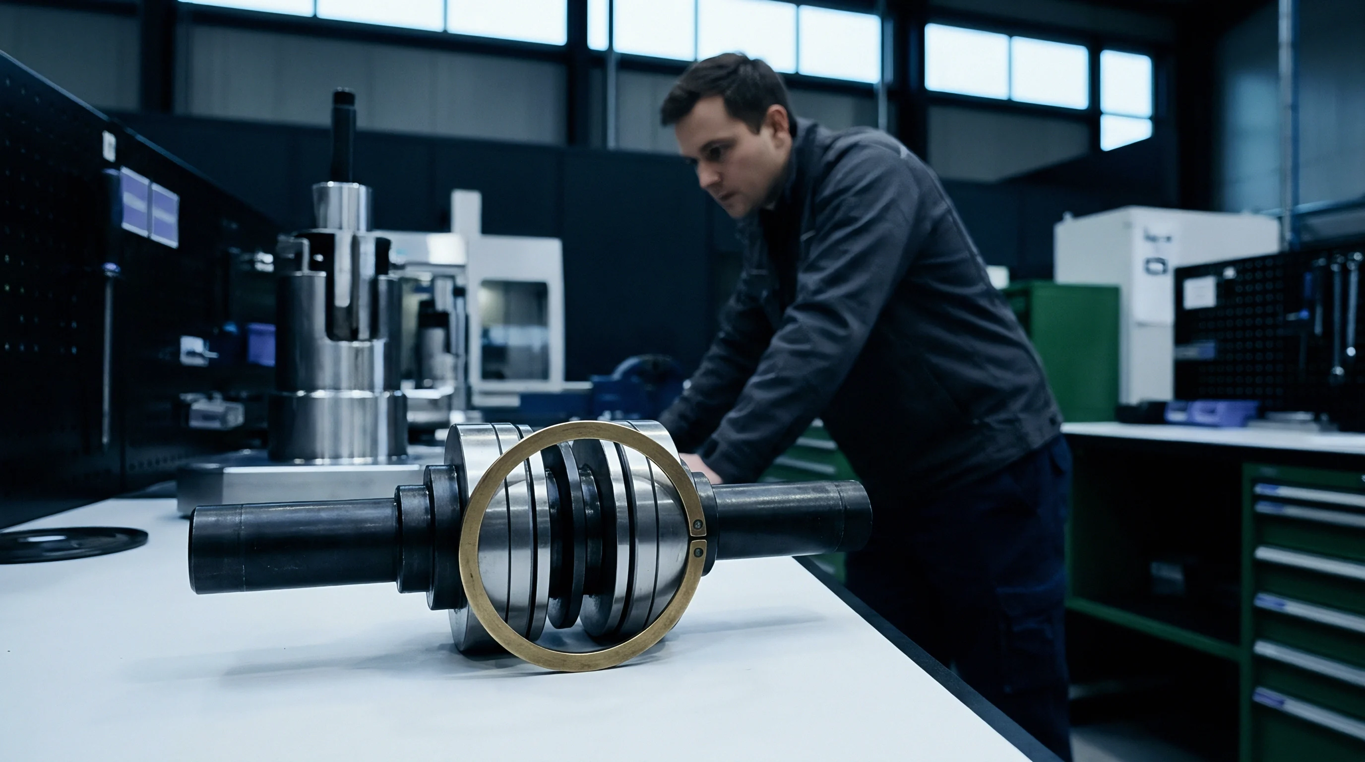
Thermal stability qualification demands that machine tools maintain accuracy across uninterrupted production periods spanning twenty-four to forty-eight hours. Running a machine center continuously without warm-up cycles produces a progressive drift pattern that creates split distributions in part inspection data. Parts machined during morning shift startup differ systematically from parts cut during late afternoon steady-state conditions.
Establishing automated warm-up macros that exercise spindles and axes through typical operating cycles brings the machine structure to thermal saturation before production begins, stabilizing the tolerance band.
Environmental enclosure control stabilizes the shop atmosphere surrounding high-precision machinery. Enclosing machine tools in thermal cleanrooms holding room temperatures within plus or minus zero point five degrees Celsius prevents outdoor diurnal temperature swings from compromising accuracy. When facilities lack isolated thermal cleanrooms, localized micro-enclosures built around individual machines establish localized laminar airflow barriers, shielding the machine casting from overhead crane movements, loading dock draft openings, and exterior wall solar loads.
Commercial Terms for Thermal Stability Acceptance
Procurement agreements for precision machining equipment must specify thermal drift acceptance testing alongside traditional static laser kinematic alignment. Machine tool acceptance protocols governed by international machine tool testing standards evaluate positional deviation under continuous dynamic axis and spindle exercise over twelve-hour test windows. Requiring suppliers to demonstrate drift containment under operational load protects buyers from purchasing machines that pass cold static alignment checks yet fail under continuous cutting conditions.
Machining contracts requiring qualification under ISO 10791-10 demand that suppliers prove volumetric drift containment within specified boundaries across continuous multi-hour test cycles before final capital release.