Archard Wear Modeling for High-Velocity Transfer Tooling Locators
Archard wear modeling predicts high-velocity locator degradation, enabling planned tooling changeouts that prevent catastrophic transfer press dimensional drift.

Flank
Transfer presses operating above twenty-five strokes per minute introduce kinematic acceleration spikes that transform sheet-metal locating from a kinematic resting problem into an aggressive tribological wear event. When high-strength low-alloy steels or hot-stamped boron grades enter a die cavity at two meters per second, the guide pins and pilot locators absorb severe normal impact loads followed by high-speed sliding over tenths of a millimeter. Toolmakers frequently discover that locators ground to precision tooling tolerances of five micrometers experience dimensional loss within fifty thousand press cycles.
This early wear destroys the functional datum nest, introducing part misplacement that cascades into flanging splits, trimmed edge burrs, and catastrophic transfer gripper collisions.
The standard mechanical engineering treatment of surface loss relies on the classical model formulated by John F. Archard. This framework expresses cumulative wear volume as directly proportional to the applied normal contact load and total relative sliding displacement, while scaling inversely with the superficial hardness of the softer contacting partner:
V = K × (F_N × s) / H
Here, V denotes total worn volume, F_N represents normal interface load, s equals sliding distance, H defines the penetration hardness of the wearing surface, and K serves as the dimensionless wear coefficient. While mathematically straightforward, transferring this classical calculation directly onto modern transfer stamping tooling yields substantial operational discrepancies. The locator contact interface does not maintain steady-state conditions.
Sliding velocity varies throughout the locator pilot penetration cycle, contact pressures regularly exceed the material compressive yield strength, and rapid micro-sliding causes interface frictional heating that alters the localized boundary layer microstructure.
A locator operating under extreme boundary lubrication conditions exhibits severe adhesive wear whenever local surface flash temperatures break down additive films.
High-velocity transfer tooling locators experience severe cyclic transient states. During the initial thirty milliseconds of locator engagement, dynamic impact forces generate transient contact stresses exceeding twelve hundred megapascals across contact lands narrower than two millimeters. When the blank slips down the locator lead-in angle into its final nest position, the instantaneous sliding velocity reaches its peak precisely where contact stress concentrates.
Tooling engineers who treat the Archard wear coefficient K as a static scalar discover that operational locator wear rates diverge from initial analytical models by more than an order of magnitude.
Dynamic Insertion Kinematics in High-Speed Automation
Automation rails in modern crossbar and three-axis transfer presses accelerate stamped sheet panels across die stations with transfer cycle times under two seconds. The locator entry profile must center incoming parts carrying spatial delivery errors up to three millimeters caused by gripper jaw compliance and aerodynamic panel flutter. High-speed video diagnostics verify that the sheet metal blank edge strikes the conical or bullet-nosed lead-in angle of the locator with vertical velocities between 0.8 and 1.5 meters per second, accompanied by horizontal lateral velocities up to 0.4 meters per second.
This kinetic contact produces an asymmetric impact phase followed immediately by a forced positioning stroke. As the transfer automation releases the panel, the locating pin forces the metal blank into alignment against opposing nest blocks, dragging the blank sheet gauge edge across the locator flank under the full kinetic energy of the incoming panel. Tool steels such as AISI D2 or powdered-metallurgy grades like Vanadis 4 Extra experience severe contact stress concentrations along this contact band.
The sliding distance s within each press cycle appears modest, typically spanning 1.5 to 4.0 millimeters along the locator flank. Over a standard automotive production campaign of five hundred thousand panels, this sliding action accumulates several kilometers of localized frictional travel under contact pressures that strip away thin protective oxide coatings.
The dimensional consequence arrives without warning. A reduction in locator diameter of twenty-five micrometers allows the stamped sheet to rotate by 0.08 degrees across an eight-hundred-millimeter body side panel. That tiny rotational shift moves critical secondary pierce holes outside their geometric position tolerance.
Stamping plants then compensate by manually shimming locators or widening die clearances, masking the underlying wear problem while degrading vehicle body dimensional repeatability.


Pin
Precision pilot locators, commonly machined as 2-way diamond pins or 4-way round bullet pins, dictate the dimensional repeatability of every downstream forming and trimming operation. The geometry of the locator tip establishes the physical boundary conditions governing the Archard equation. Standard tool design manuals specify bullet, parabolic, or conical lead-in tapers transitioning into a cylindrical land that sets final part placement.
The contact transition point between the lead-in angle and the cylindrical sizing land carries the highest wear vulnerability across the entire locating assembly.
During initial entry, the contact geometry resembles a cylinder-on-flat or crossed-cylinders configuration, concentrating normal loads onto an apparent contact area smaller than three square millimeters. Stamping press technicians frequently find that modifying the locator geometry alters the wear pattern far more substantially than changing the tool steel alloy. When a lead-in angle is cut steeper than thirty degrees to maximize locator vertical clearance, dynamic entry forces jump by sixty percent due to unfavorable contact wedge mechanics.
The normal force F_N acting perpendicular to the locator flank escalates, accelerating localized volumetric wear.
Geometric Influence on Contact Mechanics
Spherical bullet-nose geometries distribute the initial impact across a continuous radius, preventing the severe gouging observed on locators ground with sharp chamfer transitions. However, as the sheet advances past the spherical crown onto the vertical locating land, the instantaneous contact area contracts into a narrow horizontal band along the pin flank. Finite element contact analyses show that contact stress spikes precisely at the tangent line between the radius and the vertical sizing land.
This focal zone causes localized material displacement. The softer sheet metal workpiece, typically drawing quality steel or work-hardened aluminum alloy, sheds microscopic metallic debris that accumulates along the pin flank. In dry or wash-lubricated stamping operations, this debris promotes three-body abrasive wear, cutting vertical micro-grooves into the locator surface.
Diamond-shaped pilot pins, utilized to establish 2-way locating without over-constraining the panel, display even greater sensitivity. Wear concentrates heavily on the two active locating flats, creating concave wear pockets that ruin locator accuracy while total pin diameter remains unchanged across inactive faces.
| Tool Material Grade | Heat Treatment State | Surface Hardness (HRC) | Compressive Yield (MPa) | Calibrated Wear Coeff K (10e-6) |
|---|---|---|---|---|
| AISI O1 Tool Steel | Quenched and Tempered | 58 | 1850 | 8.4 |
| AISI D2 Tool Steel | Cold Work Vacuum Hardened | 60 | 2150 | 4.2 |
| Bohler K340 Isodisc | Secondary Hardened ESR | 62 | 2300 | 2.1 |
| Uddeholm Vanadis 4 Extra | Powder Metallurgy Tempered | 63 | 2450 | 1.1 |
| Carbide Grade ISO K30 | Sintered Tungsten Carbide | 76 | 3800 | 0.3 |
The operational data summarized above illustrates why standard tool room steel selections fail early in high-speed transfer operations. Moving from standard D2 tool steel to a high-vanadium powder-metallurgy grade reduces the dimensionless wear coefficient K by nearly seventy-five percent under identical contact pressures. This reduction stems from the dense dispersion of hard vanadium carbides (MC type, exceeding 2800 HV), which resist micro-plowing from burred sheet metal edges.
However, high hardness alone provides incomplete protection if the base substrate lacks sufficient compressive yield strength to prevent plastic collapse underneath the contact zone.
Contact
Implementing the Archard formulation in automated transfer stamping requires a transition from global macroscopic values to localized, surface-resolved contact variables. Instead of treating the pin as a single wearing entity, modern boundary modeling divides the contact area into discrete surface patches. Within each patch, the differential wear depth h varies across incremental time steps as a function of the local contact pressure, local sliding velocity, and localized interface hardness:
dh(x,y,t) / dt = k_local × P(x,y,t) × v_rel(x,y,t)
In this local differential formulation, h(x,y,t) represents the linear wear depth normal to the surface, k_local defines the specific dimensional wear rate expressed in cubic millimeters per Newton-meter, P(x,y,t) denotes the instantaneous contact pressure, and v_rel(x,y,t) reflects the tangential sliding velocity between the sheet edge and locator flank. Integrating this equation across one full press stroke yields the wear footprint left by a single cycle:
h_cycle(x,y) = ∫ k_local × P(x,y,t) × v_rel(x,y,t) dt
Contact pressure P(x,y,t) remains intensely non-linear throughout panel locating. When the blank edge initially strikes the locator flank, contact area is governed by rough surface micro-asperity compliance. Because the sheet metal blank edge is formed by mechanical shearing, it possesses a severe cross-sectional profile consisting of a rollover zone, a burnish band, a fractured zone, and an exit burr.
The hard, work-hardened fracture burr concentrates the entire normal load onto razor-thin contact points, creating localized contact pressures that easily surpass three thousand megapascals.
- Subsurface Shear Stress Accumulation drives micro-crack initiation beneath the locator skin when dynamic contact pressures exceed the elastic limit of the tool steel matrix.
- Boundary Lubricant Film Evaporation occurs along micro-asperity peaks as sliding flash temperatures surpass two hundred degrees Celsius during rapid blank deceleration.
- Workpiece Galling and Adhesive Transfer welds microscopic flakes of galvanized zinc or bare aluminum sheet directly onto the locator flank, altering local friction characteristics.
- Abrasive Micro-Plowing and Furrowing cuts continuous axial tracks into the locator surface when detached zinc oxides and work-hardened steel particles slide across the land under heavy clamp loads.
The shear edge condition of the sheet metal represents the single most volatile input into locator wear models. An unclipped burr pointing downward toward the locator base increases instantaneous contact pressure fivefold compared to a deburred or tumbled edge. Locator wear models that fail to incorporate blank shearing quality inevitably underestimate physical surface loss by several hundred percent.
Thermal generation during high-rate sliding introduces further modeling complexity. In transfer presses operating at thirty strokes per minute, a locator contacts thirty parts every sixty seconds, allowing minimal dwell time for heat dissipation into the die shoe. The surface temperature of the locator land rises steadily, frequently stabilizing between 140 and 190 degrees Celsius.
This elevated temperature softens secondary tool steel matrices, drops the dynamic viscosity of stamping lubricants down to fractions of their ambient rating, and drives localized k_local values into aggressive wear regimes.
Stamping die locators operating above eighty strokes per minute demonstrate a sixty percent drop in lubricant boundary film thickness due to thermal thinning at the interface.
When the local oil film collapses, the locator surface transitions into an unlubricated sliding regime where the Archard wear coefficient spikes by two orders of magnitude. The physical mechanism shifts from mild oxidative wear into severe adhesive galling, transferring sheet metal fragments onto the locator flank until the entire mechanism seizes inside the locating bushing.

Gauge
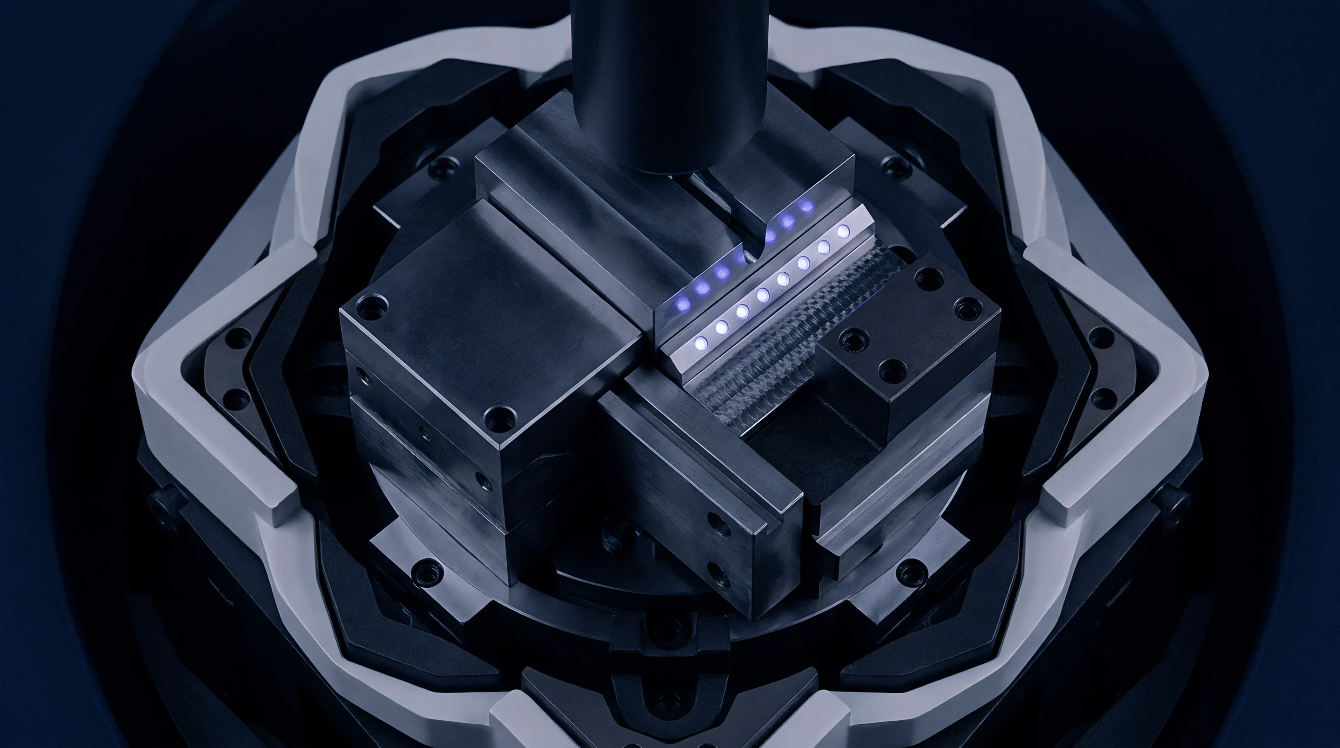
Validating an Archard locator wear model requires precise physical measurement across production stamping campaigns. Stamping tool rooms historically tracked locator wear using manual micrometers or vernier calipers during scheduled weekend die maintenance. These manual measurements provide rough global diameters but fail to capture the asymmetric, localized wear scars that cause locating failure.
Accurate empirical validation demands optical coordinate metrology, tactile contour profiling, and surface topography tracking taken at precise production intervals.
The Diligence Examiner approaches locator metrology as an evidentiary sequence. Measuring a locator after a die has produced three hundred thousand parts tells you that wear occurred, but it obscures the progression rate and masks non-linear transitions between mild running-in wear and runaway catastrophic galling. Tooling verification programs mandate structured inspection intervals recorded at ten thousand, fifty thousand, one hundred thousand, and two hundred and fifty thousand cycles.
These discrete time-series measurements allow stamping engineers to calibrate specific wear rate constants against actual operating conditions.

Are Optical Scanners Sufficient for Precision Wear Verification?
White light interferometry and structured light optical 3D scanners offer rapid non-contact digitization of complex tooling surfaces. An optical scan captures millions of point coordinates across the locator bullet nose, flank land, and base shoulder within minutes, generating full 3D color error deviation maps against original CAD nominal surfaces. However, optical scanning encounters severe measurement limits when inspecting highly reflective, polished tool steels or surfaces wet with semi-synthetic forming lubricants.
Residual oil films as thin as two micrometers distort optical fringe patterns, introducing measurement errors that equal the entire allowable wear tolerance of a precision pilot pin. Clean room solvent washing and surface matting sprays are required to achieve sub-micron repeatable optical readings. Furthermore, optical scanners struggle to resolve deep, narrow micro-grooves caused by edge burr scratching due to optical triangulation shadow effects along steep locator flanks.
High-precision tactile coordinate measuring machines (CMM) utilizing diamond-tipped styli remain mandatory to measure cross-sectional diameters within an uncertainty band of ±0.5 micrometers.
| Measurement Technology | Vertical Resolution (μm) | Lateral Spatial Limit (μm) | Inspection Speed per Pin | Lubricant Film Sensitivity |
|---|---|---|---|---|
| Benchtop Vernier Micrometer | 2.0 | 1000.0 | 30 Seconds | High (Oil Compression Bias) |
| Contact Stylus Profilometer | 0.01 | 1.5 | 3 Minutes | Low (Stylus Cuts Film) |
| Tactile 3D Micro-CMM | 0.1 | 10.0 | 8 Minutes | Medium (Requires Solvent Wipe) |
| Structured Light 3D Scanner | 1.5 | 15.0 | 2 Minutes | Severe (Requires Anti-Glare Prep) |
| Confocal White Light Microscope | 0.005 | 0.2 | 15 Minutes | Severe (Zero Contamination Limit) |
Surface roughness tracking provides an early warning indicator of transition states in the Archard model long before significant dimensional loss becomes measurable on a CMM. Virgin locators are typically finish-ground and polished to an average roughness Ra between 0.1 and 0.2 micrometers. During the initial running-in stage of the press tool, micro-asperity peaks shear off, often reducing Ra to a polished finish near 0.05 micrometers.
This initial smoothing corresponds to an artificially low Archard wear coefficient.
Once cyclic fatigue initiates surface micro-pitting, or when localized adhesive pickup begins, the surface roughness spikes sharply. The maximum peak-to-valley height Rz jumps from less than one micrometer to over six micrometers. This sudden increase in surface roughness alters the local friction coefficient, elevating tangential shear forces during blank insertion and accelerating volumetric wear in a self-reinforcing failure loop.


Drift
Dimensional degradation of transfer press locators does not remain isolated at the locating station. It sets off progressive dimensional drift throughout the entire stamping die sequence. Modern transfer stamping dies for structural automotive body components contain between five and eight consecutive stations: draw, trim, pierce, flange, restrike, and separation.
The sheet metal part moves through these operations held by mechanical automation fingers and positioned at each station by dedicated pilot pins that engage identical locating holes pierced in the initial station.
When the pilot locators in Station 2 wear by thirty micrometers, the panel shifts by that same magnitude during the primary trimming operation. In Station 3, new locators engage the previously pierced pilot holes to position the panel for secondary piercing. Because the panel was trimmed thirty micrometers off-nominal in Station 2, the scrap trim line shifts relative to the pierced holes.
As this geometric error propagates through downstream flanging and restrike stations, dimensional errors compound linearly and non-linearly across the part features.

Root-Sum-Square Kinematic Misalignment Propagation
Statistical dimensional engineering models cumulative panel location error using both worst-case kinematic stack-up and root-sum-square (RSS) statistical distributions. In high-velocity transfer tooling, the actual clearance between the sheet locator hole and the locator pin diameter directly governs the spatial variance band of the stamped part. The total horizontal spatial displacement error E_total across two widely spaced locating pins is calculated using the mechanical hole-to-pin clearances and locator flank wear values:
E_total = √
Within this equation, c_nominal represents the initial manufacturing clearance between the locator pin and the stamped pilot hole (typically fifty micrometers), w_pin1 and w_pin2 denote the linear wear depth accumulated on each respective locator flank, and e_press defines the cyclic mechanical repeatability error of the press transfer automation system. When locators are new, total panel positional variance stays comfortably within an allowable process window of ±0.08 millimeters. As pin wear accumulates to fifty micrometers per side, the positional variance expands beyond ±0.18 millimeters.
- Hole Edge Flange Tearing occurs when off-center pilot locators strike the perimeter of pre-pierced sheet metal holes during rapid die closure, producing severe metal deformation and burrs.
- Trimming Die Clearance Asymmetry shifts uniform clearance gaps between upper and lower cutting steels, causing localized edge burrs along one side of the panel and tensile fracture rollover on the opposite side.
- Secondary Flange Angle Variation manifests when improperly nested panels slip during upper pad clamping, altering developed flange lengths by several tenths of a millimeter.
- Transfer Automation Gripper Faults trigger automated press line emergency stops when panel misplacement prevents pneumatic vacuum cups or mechanical gripper fingers from seating correctly on designated pickup zones.
Statistical process control charts monitoring critical part dimensions via downstream inline laser measurement stations invariably detect locator wear as a steady, monotonic drift in process mean values. While the process dispersion (short-term standard deviation) remains constant, the mean dimensional location drifts consistently toward the worn side of the locator. Quality engineers frequently misdiagnose this steady drift as incoming raw material coil thickness variation or stamping lubricant batch inconsistency, making futile adjustments to blankholder nitrogen gas spring pressures while the physical locator pins continue to lose metal.


Shield
Mitigating high-velocity locator wear requires aggressive surface engineering to reduce the Archard wear coefficient K while dramatically increasing superficial surface hardness H. Tool designers rely on chemical vapor deposition (CVD), physical vapor deposition (PVD), thermo-reactive diffusion (TRD), and specialized nitriding treatments to establish hard wear-resistant barrier layers across precision locators. These advanced surface coatings fundamentally alter the tribological contact interface between tool steel and sheet metal.
The operational choice of protective coating is dictated by the specific sheet material running through the transfer die. Stamping galvanized advanced high-strength steels (AHSS) presents an entirely different tribological challenge than forming bare aluminum alloys. Zinc coatings on galvanized steels easily melt or soften under high sliding pressures, adhering aggressively to standard tool steel surfaces and initiating severe zinc galling.
Aluminum alloys generate hard aluminum oxide particles that act as fine abrasive media, scouring soft coating matrices and cutting away base materials.

PVD versus CVD Coating Performance under Severe Impact
Physical Vapor Deposition applies ceramic thin films at process temperatures between 400 and 500 degrees Celsius, preserving the core hardness and dimensional tolerances of vacuum-hardened tool steels without inducing thermal distortion. Titanium Aluminum Nitride (TiAlN) and Chromium Nitride (CrN) coatings deposited via cathodic arc PVD exhibit micro-hardness values between 2800 and 3400 HV, coupled with friction coefficients below 0.35 against oily sheet steel. These PVD layers drop the Archard wear coefficient K by more than an order of magnitude compared to uncoated D2 tool steel.
However, PVD thin films typically possess a total thickness of only two to four micrometers. Under the violent, dynamic impact loads encountered on high-velocity transfer tooling locators, these thin ceramic coatings frequently suffer eggshell failure. If the underlying tool steel substrate lacks sufficient compressive yield strength, dynamic impact forces deform the base steel elastically and plastically beneath the coating.
The ultra-hard, brittle PVD ceramic film cannot bridge this substrate deflection, causing it to crack, delaminate, and flake away from the locator flank within tens of thousands of cycles.
| Surface Engineering System | Coating Thickness (μm) | Surface Hardness (HV 0.05) | Friction Coeff vs Zinc (Dry) | Campaign Life Before Rework (Cycles) |
|---|---|---|---|---|
| Uncoated AISI D2 Through-Hardened | N/A | 720 | 0.65 | 45,000 |
| Gas Nitrided AISI D2 (Diffusion Case) | 80.0 | 1050 | 0.50 | 95,000 |
| PVD Monolayer CrN on Tool Steel | 3.0 | 2200 | 0.32 | 140,000 |
| PVD AlTiN on Plasma Nitrided Matrix | 4.5 | 3200 | 0.28 | 380,000 |
| TRD Vanadium Carbide Diffusion | 12.0 | 2900 | 0.22 | 650,000 |
| CVD Multilayer TiC/TiN Coating | 9.0 | 3300 | 0.20 | 800,000 |
To eliminate eggshell delamination, premium transfer tooling specifications enforce hybrid surface treatments. Toolmakers first subject the machined and hardened locator to deep plasma nitriding, creating a graduated diffusion case extending eighty to one hundred micrometers into the tool steel matrix with a supported surface hardness near 1000 HV. A high-hardness PVD or PACVD (Plasma-Assisted Chemical Vapor Deposition) coating is then synthesized directly onto this nitrided case.
The nitrided diffusion layer provides the mechanical load-bearing capacity needed to resist heavy dynamic impact stresses, preventing substrate deformation and allowing the outer ceramic film to resist sliding wear indefinitely.
Duplex surface systems incorporating deep diffusion nitriding beneath PVD coatings eliminate interfacial delamination under dynamic contact pressures up to three gigapascals.
Thermo-Reactive Diffusion (TRD), commonly known as the Toyota Diffusion process, provides another exceptional protective mechanism for severe wear conditions. By immersing high-carbon tool steels in a high-temperature molten borax bath containing vanadium and niobium ferroalloys, carbon atoms diffuse outward from the tool steel matrix to form a metallurgical layer of vanadium carbide (VC) ten to fifteen micrometers thick. Because this carbide layer grows directly out of the substrate lattice rather than adhering mechanically as an overlay, it exhibits remarkable bond strength that resists spalling under severe transfer press side-thrust impact loads.
The standard procurement contract for high-speed transfer tooling explicitly bars bare tool steel locators on structural automotive body lines, mandating validated duplex coatings or solid sintered carbide inserts for any tool running above twenty strokes per minute.
Ledger
Implementing continuous Archard wear modeling transforms tooling asset management from reactive breakdown fire-fighting into a predictable financial ledger. In large-scale automotive and industrial stamping operations, unexpected press stoppages carry crippling financial overheads. When a pilot locator fails in production, the entire stamping line stops.
Operating costs for a high-speed transfer press line range between eight hundred and fifteen hundred dollars per hour, converting an unpredicted thirty-minute locator replacement into a substantial commercial loss before factoring in the cost of scrap parts produced prior to detection.
The Sequencing Strategist evaluates Archard wear calculations as a capital decision-making framework. By linking real-time press counter data to a calibrated wear algorithm, plant managers can accurately forecast the remaining useful life (RUL) of every locating element in a die set. This predictive capability enables maintenance teams to plan locator replacements during scheduled die changeovers and planned weekend maintenance windows, entirely eliminating unscheduled line stops driven by broken or worn pilot pins.

Predictive Replacement Arithmetic and Economic Optimization
Consider a practical operational calculation for a high-volume automotive transfer press line stamping galvanized DP800 dual-phase steel crossmembers at twenty-eight strokes per minute across three production shifts: take an annual planned production volume of 1.2 million parts, assume an initial locator manufacturing clearance of sixty micrometers, and set the maximum tolerable diametral wear threshold at forty micrometers before part quality limits are violated.
If tool engineering equips the die with conventional uncoated AISI D2 pilot pins exhibiting an operational wear rate of 0.85 micrometers per ten thousand strokes, the locators exceed their allowable wear limit after only 470,000 cycles. Across the 1.2-million-part campaign, the die requires three unexpected tooling changeouts, forcing over twelve hours of unscheduled line downtime totaling approximately $14,400 in direct lost press capacity, plus the cost of scrap panels produced during wear transitions.
Conversely, investing in powdered-metallurgy Vanadis 4 Extra pins treated with a duplex plasma-nitrided and AlTiN PVD coating reduces the verified wear rate to 0.08 micrometers per ten thousand strokes. The same forty-micrometer wear limit now extends locator operating life beyond 5.0 million cycles, covering the entire multi-year vehicle manufacturing platform without a single production replacement. The incremental capital expenditure of four hundred dollars per locator pin generates an immediate ten-to-one return in avoided line stoppage costs during the first six months of production.
Beyond direct line stoppage savings, maintaining tight locator clearances stabilizes downstream automated assembly plants. In robotic resistance spot-welding cells, panel-to-panel gaps caused by stamped part locating errors lead to severe weld spatter, weak nugget formation, and automated weld tip fouling. By stabilizing part geometry through rigorous tribological wear tracking at the stamping stage, manufacturers prevent costly downstream dimensional remediation in the body shop, protecting overall operating margins across the entire industrial enterprise.
Yet, mathematical models remain subject to unaccounted operational disruptions: an unannounced reduction in blank lubricant washing efficiency by an upstream coil processing line can instantly alter the boundary friction state, rendering even the most sophisticated predictive maintenance projections obsolete overnight.