Surface Melt Fracture Onset Limits in Polyolefin Profile Extrusion
Surface melt fracture limits in polyolefin profile extrusion are governed by critical wall shear stress thresholds between 0.08 and 0.14 MPa at the die exit.


Stress
Profile extrusion lines running linear low-density polyethylene or high-density polyethylene hit an operational ceiling long before motor torque or heater capacities saturate. That ceiling manifests at the die exit land as periodic surface matte finishes, fine transverse ridges, or severe volumetric distortion. The physical trigger for surface melt fracture, commonly termed sharkskin, is the rapid acceleration of the polymer melt skin as it leaves the die land friction zone to form an unconstrained profile surface.
At the exit lip, the boundary layer undergoes localized tensile elongation speeds that exceed the strain-at-break of the high-molecular-weight polymer chains. Shear stress along the die wall reaches a critical value where wall slip transitions from steady molecular detachment to unsteady stick-slip oscillations.
Determining the exact point of surface melt fracture onset requires calculating wall shear stress inside the die land geometry. For non-Newtonian polyolefin melts exhibiting power-law shear thinning behavior, nominal wall shear stress relates directly to pressure drop across the die land and the hydraulic radius of the profile cross-section. The classic expression for wall shear stress in a slit profile die multiplies the pressure drop across the parallel land by the die gap half-thickness and divides it by the total land length.
When this calculated stress crosses a threshold between 0.10 MPa and 0.14 MPa for conventional linear low-density polyethylenes, microscopic surface tearing becomes visible under low-power magnification. High-density polyethylene profiles show onset at lower stress values, frequently between 0.08 MPa and 0.12 MPa, owing to a narrow molecular weight distribution and reduced chain entanglement density.

Shear Stress Thresholds across Polyolefin Resins
The transition from a smooth profile surface to sharkskin melt fracture depends on melt viscosity, extrusion temperature, resin architecture, and shear rate. Operating at melt temperatures of 190 degrees Celsius to 210 degrees Celsius provides a baseline, but raising temperature to reduce viscosity yields diminishing returns because melt strength drops at the same time, weakening the skin against exit tensile failure.
| Polyolefin Polymer Type | Melt Index (g/10 min at 190C) | Density (g/cm3) | Critical Shear Stress (MPa) | Apparent Shear Rate at Onset (1/s) |
|---|---|---|---|---|
| Ziegler-Natta LLDPE (C8 Octene) | 1.0 | 0.920 | 0.135 | 420 |
| Metallocene LLDPE (mLLDPE) | 1.0 | 0.918 | 0.105 | 260 |
| Bimodal High-Density PE (Pipe/Profile) | 0.25 | 0.949 | 0.090 | 180 |
| Unimodal HDPE (Blow/Extrusion) | 0.75 | 0.954 | 0.115 | 310 |
| Polypropylene Homopolymer | 2.0 | 0.905 | 0.160 | 650 |
Metallocene-catalyzed polyethylenes present severe processing limits due to their narrow molecular weight distribution. Where broad distribution resins feature low-molecular-weight fractions that act as internal lubricants, metallocene polyolefins lack these fractions, causing wall shear stress to climb rapidly even at modest line speeds. Wall shear rate calculations must apply the Weissenberg-Rabinowitsch correction to account for non-Newtonian velocity profiles.
Neglecting this correction underestimates actual wall shear rates by 20 to 35 percent, leading tool designers to specify die lands that initiate melt fracture during initial ramp-up.
The exit singularity creates high local stress concentrations right at the metal edge. As the fluid element exits the land, the velocity profile transforms instantly from a parabolic shape with zero speed at the wall to a uniform plug-flow velocity profile across the section. This acceleration imposes severe stretching along the outer melt layer.
When local tensile stress exceeds cohesive melt strength, microscopic fractures open along the surface. Increasing line speed turns these microscopic tears into visible, periodic ridges that breach dimensional tolerances and surface roughness specifications.
Linear low-density polyethylene extruded at 200 degrees Celsius through an uncoated tool steel die land exhibits sharkskin surface melt fracture when wall shear stress crosses 0.13 MPa.
Entrance effects upstream of the die land also contribute to gross volumetric melt fracture. When melt enters a tapered die entry from a larger breaker plate cavity, excessive converging contraction angles create extensional stress fields. Elastic strain accumulating in the barrel throat manifests as wavy extrudate or helical distortion downstream of the exit lip.
Distinguishing pure surface sharkskin from gross melt fracture remains vital: surface sharkskin originates exclusively at the die exit lip, whereas gross melt fracture originates in the die entrance zone or die land channel body. Controlling entrance geometry reduces total pressure drop, but surface sharkskin onset limits remain dictated strictly by exit land stress conditions.
Operating an extrusion line right at the onset threshold leaves little margin for variation. Minor shifts in barrel zone heat, slight lot-to-lot resin density drift, or room drafts will push wall shear stress over the boundary. The standard floor response ~ slowing line speed by 10 to 20 percent to clear the finish ~ sacrifices hourly output while fixed plant overhead continues to accumulate at the same rate, cutting directly into unit margins.
Unchecked wall shear stress ruins surface finish long before parts distort dimensionally. Recovering a clean profile without sacrificing line speed requires changing melt elasticity, altering die-wall friction, or redesigning the land geometry itself. Leaving exit shear unmanaged simply produces steady scrap, rejected shipments, and lost machine hours.


Resin
Resin formulation and additive architecture govern the exact boundary where surface melt fracture takes hold. Polymer manufacturers tune molecular weight distributions, short-chain branching distributions, and long-chain branching frequencies to balance physical profile properties against extrudability. High-molecular-weight fractions deliver high environmental stress crack resistance and structural impact strength in building profiles, yet these same long chains increase melt relaxation times and elevate wall shear stress inside the die.
Balancing structural specifications against throughput targets requires detailed analysis of resin melt rheology.
Fluoropolymer processing aids, frequently supplied as fluoroelastomer masterbatches, shift the surface melt fracture limit to significantly higher shear rates. These additives function by bleeding out of the bulk polyolefin matrix during extrusion, depositing a thin dynamic fluoropolymer coating on the metal surfaces of the die land. Because polyolefins show extremely low adhesion to fluoropolymer layers, interfacial slip replaces the traditional zero-velocity boundary condition at the wall.
Wall shear stress drops immediately below the critical threshold for sharkskin onset, allowing line speed increases of 30 to 100 percent without surface distortion.

Additives and Interfacial Dynamics
Achieving a stable wall coating during startup demands continuous transport of fluoropolymer droplets to the die boundary. Droplet size dispersion inside the masterbatch determines how fast this dynamic coating accumulates. Droplets smaller than 0.5 micrometers remain trapped in the bulk polyolefin flow core without migrating to the die walls.
Droplets larger than 5 micrometers shear apart into irregular ribbons, delaying uniform coverage. Effective processing aids maintain dispersion droplet sizes between 1 micrometer and 3 micrometers.
Additive performance varies across product classes, chemical configurations, and active concentration levels within polyolefin profile formulations.
- Fluoroelastomer Copolymer Additives establish baseline wall coating layers within two hours of continuous resin purge, dropping die wall shear stress by up to 40 percent.
- Fluoropolymer-Polyethylene Glycol Blends speed up die surface conditioning by using low-molecular-weight glycol carrier phases to accelerate interfacial migration.
- Non-Fluorinated Olefinic Processing Aids use modified polar blocks to bond with metal die walls, offering fluorine-free alternatives for regulatory compliance.
- Synergistic Inorganic Nanoparticle Compounds reinforce lubricant layers, delaying shear-induced additive stripping under extreme pressure profile runs.
Conditioning time represents a major hidden cost during resin changes or line start-ups. Establishing a fully functional fluoropolymer coating layer on a clean die land requires processing between 200 kg and 500 kg of additive-treated resin. During this period, wall slip remains non-uniform, causing temporary dimensional variations and rough surface spots.
Extrusion teams running short batch orders often spend a substantial fraction of shift time just trying to establish steady-state additive coverage.
Processing aids establish interfacial wall slip, lowering wall shear stress without changing bulk polyolefin melt viscosity.
Interference from competing additives can destroy processing aid performance. Inorganic pigments like titanium dioxide, calcium carbonate fillers, and silica anti-block agents act as abrasive scourers inside the die land, continually scraping away the soft fluoropolymer coating deposited on the metal wall. When filler loadings exceed 5 weight percent, additive consumption rises dramatically.
Compounders must increase polymer processing aid additions from 300 parts per million up to 1200 parts per million to compensate for this continuous scouring.
Hindered amine light stabilizers and acidic carbon black grades also neutralize processing aids through chemical adsorption. Acidic sites on pigment surfaces bind active fluoropolymer chains, preventing them from migrating to the die wall surface. Resin buyers specifying custom colors for exterior profiles frequently discover that a processing aid package validated on clear natural resin fails entirely when compounded into dark UV-stabilized formulations.
Pre-compounded polyolefin grades with standard off-the-shelf processing aid packages rarely perform uniformly across differing die profiles. Without measuring actual exit shear stress, tooling geometries with complex cross-sections will strip the fluoropolymer layer faster than the melt can deposit it, bringing the line down unexpectedly.


Die
Die land geometric design controls velocity gradients, pressure drops, and shear stress profiles across the extrudate cross-section. Machining precision inside the die land determines whether wall shear stress stays uniform across complex profile shapes. Narrow web sections in hollow window profiles experience far higher local shear rates than thick corner blocks.
If shear stress in thin profile legs exceeds the critical melt fracture threshold while thick sections remain below it, localized sharkskin appears exclusively along specific flanges, corrupting structural welds downstream.
Selecting extrusion die land length involves a direct tradeoff between pressure drop and flow stabilization. Longer land lengths smooth out upstream entrance turbulence and equalize internal flow distribution, but they escalate total die pressure drop and elevate shear strain energy. Short land lengths minimize pressure drop and decrease barrel backpressure, but offer insufficient residence time to damp out stress history from converging entrance zones.
Land length to gap thickness ratios for linear polyolefin profile dies typically range between 10:1 and 25:1, depending on profile wall thickness.
Does Die Land Tapering Eliminate Exit Stress?
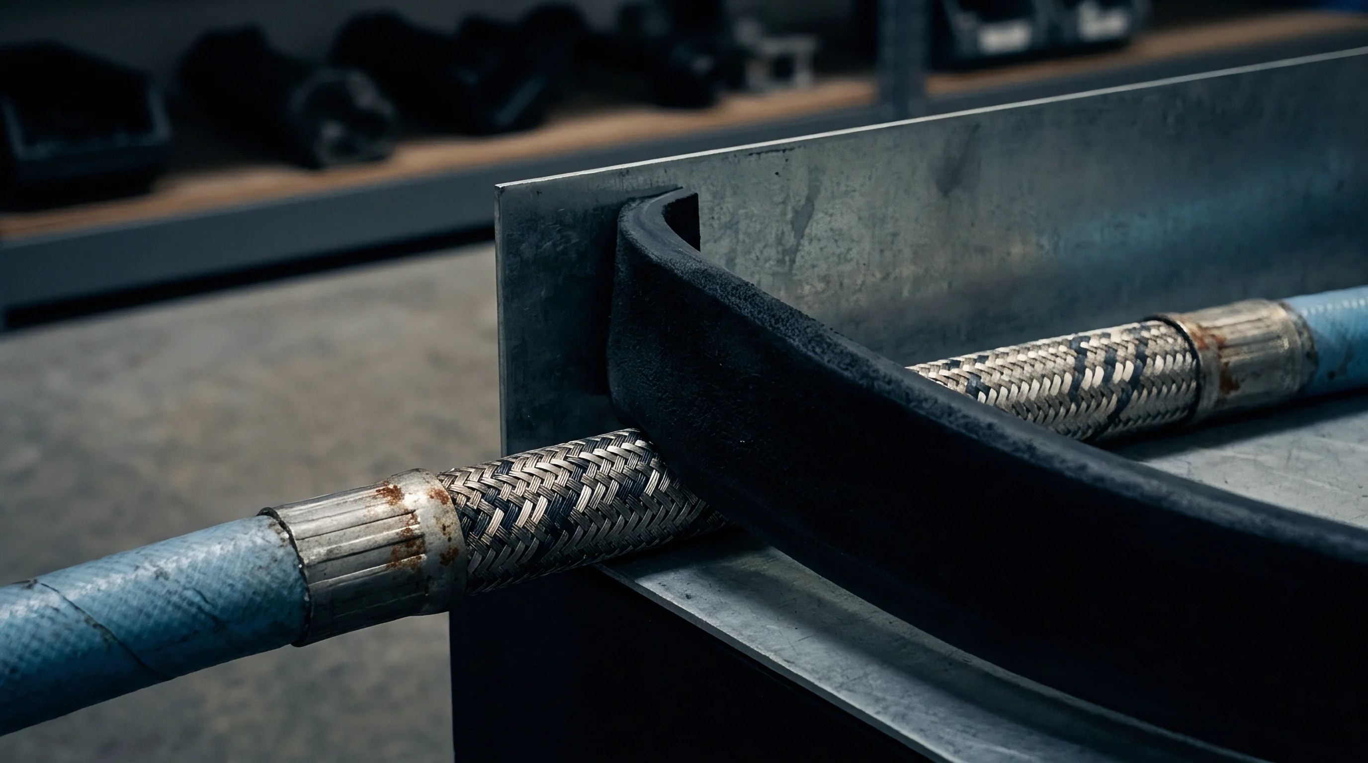
Tapering the final exit section of a profile die land alters local shear stress gradients immediately upstream of the open air discharge. Adding a slight flare or outward relief angle between 0.5 degrees and 2.0 degrees over the final 2 mm of land length decreases localized extensional velocity gradients as the skin exits the tool. This gradual pressure release lowers peak tensile stress at the exit boundary layer, delaying surface fracture onset without requiring additional processing additives.
- Measure Profile Wall Differential to pinpoint localized regions where channel gaps narrow and shear rates spike.
- Calculate Sectional Hydraulic Radii across each segment of the profile die plate to evaluate localized shear stress distribution.
- Apply Differential Land Lengths by lengthening die lands in thick sections and shortening lands in narrow flanges to balance exit velocities.
- Incorporate Exit Chamfers with precise 1-degree relief angles along high-shear profile exit edges to mitigate skin tension spikes.
- Polish Die Exit Lips to a mirror finish with diamond compound to eliminate micro-grooves that seed localized tensile failure tears.
Tooling material selection and surface engineering alter interfacial friction dynamics inside the land channel. Standard tool steels like P20 or 420 stainless steel provide robust mechanical resistance, but raw steel surfaces exhibit moderate chemical affinity for polyolefin melts. Applying specialized surface coatings alters wall boundary behavior directly.
Nickel-phosphorus alloy coatings, hard chrome plating, and physical vapor deposition ceramic coatings like titanium nitride modify die surface energy. Fluorinated nickel coatings create low-energy die surfaces that induce mechanical slip without requiring continuous additive replenishment from the bulk melt. Specialized coatings must maintain tight thickness tolerances, as non-uniform application distorts profile dimensions beyond allowable limits.
Extruders who ignore local velocity matching across asymmetric profile dies face continuous line balancing problems. Thin profile legs cool rapidly inside vacuum sizing tanks, while localized melt fracture along high-shear edges prevents tight seal engagement. Simple rules of thumb regarding die land ratios fail when applied to complex hollow profiles with non-uniform wall thicknesses.


Yield
Surface melt fracture limits dictate the commercial operating envelope of polyolefin profile extrusion lines. When melt fracture appears, line speed must drop or processing aid consumption must increase. Continuing production with active sharkskin defects generates instant industrial scrap.
While scrap can theoretically be reground and blended back into virgin resin streams, regrind limits carry severe physical and financial boundaries that hit line productivity and working capital balances.
Regrind integration alters bulk density, melt index uniformity, and thermal history of the feedstock. Remelting polyolefins drives thermo-oxidative chain scission and cross-linking, shifting molecular weight distribution. Blending degraded regrind into virgin profile resin drops melt strength, causing surface melt fracture to initiate at lower wall shear stress thresholds than clean virgin polymer.
Extruders attempting to consume internal scrap frequently trigger a feedback loop where high regrind ratios induce earlier melt fracture, driving scrap rates higher.

Regrind Allowance and Margin Structure
Quality standards for structural profile extrusions place strict limits on allowable regrind percentages. In municipal pipe, fenestration profiles, and electrical conduits, standards limit regrind content to preserve structural integrity. Exceeding regrind limits reduces long-term hydrostatic strength, environmental stress crack resistance, and low-temperature impact toughness.
| Regrind Content (wt%) | Melt Index Shift (g/10 min) | Critical Shear Stress Drop (%) | Tensile Impact Retention (%) | Landed Unit Cost Modification ($/kg) |
|---|---|---|---|---|
| 0 (Pure Virgin) | 0.85 | 0.0 (Baseline) | 100.0 | $1.850 |
| 10 (Standard Internal Loop) | 0.89 | -3.5 | 98.2 | $1.795 |
| 25 (Maximum Specification Limit) | 0.96 | -9.8 | 92.5 | $1.712 |
| 40 (Excessive Recycling) | 1.12 | -18.4 | 81.0 | $1.630 |
| 50 (Contaminated Scrap Blend) | 1.35 | -27.0 | 69.4 | $1.575 |
Running high regrind levels reduces raw material purchase costs per kilogram, but the drop in critical shear stress limits line throughput speed. If a line running 25 percent regrind must slow line speed by 15 percent to avoid surface melt fracture, fixed machine-hour absorption costs increase. This rise in conversion cost frequently exceeds the material cost savings achieved by using cheap internal scrap.
To analyze the exact trade-off between line speed, additive costs, and machine absorption, consider a concrete profile extrusion operation running a 90 mm single-screw extruder producing a 450-gram-per-meter LLDPE profile. The extruder carries a direct fixed operating cost of $165.00 per machine hour, inclusive of labor, power, facility allocation, and equipment depreciation. Virgin LLDPE resin costs $1.85 per kilogram.
Fluoropolymer processing aid masterbatch costs $18.50 per kilogram, dosed at a level that adds $0.037 per kilogram to the overall compound cost at 2000 ppm active masterbatch dosing.
Baseline operation without processing aid reaches surface melt fracture onset at a line speed of 4.2 meters per minute, delivering a total throughput of 113.4 kilograms per hour. Machine conversion cost equals $1.455 per kilogram. Total material cost equals $1.850 per kilogram.
Total landed manufacturing cost before scrap equals $3.305 per kilogram.
Dosing fluoropolymer processing aid eliminates surface melt fracture, allowing line speed to increase by 45 percent to 6.09 meters per minute. Total throughput reaches 164.4 kilograms per hour. Machine conversion cost drops to $1.004 per kilogram.
Additive-treated material cost rises to $1.887 per kilogram. Landed manufacturing cost drops to $2.891 per kilogram. Expanding line output frees up 31 percent machine capacity while reducing unit product cost by $0.414 per kilogram.
Suppressing surface melt fracture yields $68.06 per operating hour in direct net savings.
Managing surface defect inspection requires rigorous automated visual quality monitoring systems. Manual inspection by machine operators fails to detect early-stage micro-sharkskin, allowing defective extrudate to pass onto storage reels. Automated inline optical cameras utilizing laser backlighting detect surface roughness spikes exceeding 2.5 micrometers Rz in real time.
Systems connected directly to extruder line controllers automate slight line speed reductions or boost additive dosing pumps when micro-fractures begin forming.
Establishing clear defect boundary metrics prevents ongoing commercial disputes between profile extruders and downstream buyers. Industrial procurement contracts define surface smoothness limits using explicit profilometer values rather than visual descriptors like smooth or commercial grade. When profile shipments land at a customer assembly plant, quality control teams re-verify surface roughness parameters under ISO 4287 standard protocols.
Standard fenestration extrusion contracts require profile surface roughness to remain below 3.0 micrometers Rz across all exposed functional faces under ISO 4287 testing.
A continuous profile extrusion line generating scrap due to unmanaged melt fracture quickly consumes operating cash flow. Regrind storage hoppers fill rapidly, locking up physical warehouse space and tying up capital in raw resin that cannot be billed to finished profile inventory. Managing surface melt fracture limits represents a core driver of total plant operational efficiency and line yield stability.
Operating lines without tight exit shear limits leads to persistent scrap during high-speed runs. Incoming inspection rejections force retroactive credits that wipe out margins on completed production, making empirical critical shear stress thresholds essential when setting throughput targets.


Capital
Surface melt fracture limits create immediate cash flow consequences across polyolefin profile extrusion operations. Equipment throughput limitations dictate how fast raw resin purchases transform into billable finished goods inventory. When melt fracture constrains line speed, the cash conversion cycle lengthens.
Money spent on resin stock, operator labor, and utility power remains locked in working capital for extended durations before invoices are generated and collected. Financing this extended working capital gap requires increased reliance on revolving credit facilities, driving up interest expenses.
Asset-based credit facilities evaluate extrusion operations through strict financial covenants, including inventory turnover ratios, debt service coverage ratios, and maximum senior debt to EBITDA multiples. When profile lines throttle output speeds by 20 percent to avoid surface defects, fixed cost absorption drops, suppressing quarterly EBITDA. Reduced EBITDA combined with elevated inventory levels degrades covenant headroom.
Lenders monitoring aged inventory and working capital velocity respond to covenant breaches by raising facility interest margins or tightening borrowing base definitions.

Working Capital Dynamics and Equipment Financing
Investing in capital equipment upgrades to bypass shear stress limits presents distinct cash outlay requirements. Retrofitting existing extruders with low-friction coated die sets, optimized land geometries, or multi-component additive dosing pumps requires immediate cash expenditure. Evaluating these capital additions requires comparing the upfront cash drain against the present value of incremental cash flows generated by higher line speeds.
| Operating Strategy | Line Throughput (kg/hr) | Annual Machine Output (Tonnes) | Fixed Conversion Cost (/kg) | Inventory Turn Velocity (Days) | Anνal EBITDA Impact () |
|---|---|---|---|---|---|
| Unassisted Baseline (Defect Throttled) | 120 | 720 | $1.375 | 48 | Baseline ($0) |
| PPA Additive Dosing (No CapEx) | 175 | 1,050 | $0.943 | 33 | +$145,000 |
| Engineered Low-Friction Die Tooling | 190 | 1,140 | $0.868 | 30 | +$198,000 |
| Full Line Retrofit (Die + Dosing + Optics) | 220 | 1,320 | $0.750 | 25 | +$285,000 |
Financing a full extrusion line retrofit through equipment leasing or term loans requires matching facility maturity against the operational life of the hardware. Capital lenders underwrite profile extruders based on proven line yield metrics and contractual order backlogs. Demonstrating that a tooling upgrade raises the melt fracture onset boundary provides tangible proof of increased production capacity, supporting higher debt capacity under commercial lending terms.
Raw material inventory commitments represent another major cash sink. Order minimums for specialized high-density or metallocene polyolefin resins mandate large advance resin purchases. Holding 60 days of virgin resin stock in silos while profile extruders run at half-speed due to melt fracture limits traps cash on the balance sheet.
In contrast, running resin fully loaded with optimized polymer processing aids frees up cash by accelerating conversion rates, allowing plant managers to cut raw resin holding days down to 20 days.
Cash flow velocity in profile extrusion relies on maximizing volumetric mass output per machine hour without crossing physical surface fracture boundaries.
Extruders operating under tight asset-based loan covenants must calculate the net cash impact of additive usage versus capital modifications. Purchasing high-performance fluoropolymer processing aids requires no upfront capital expenditure, representing a pure operational expense that scales directly with production volumes. Tooling modifications demand upfront cash outlays but offer lower recurring variable costs over multi-year production runs.
Calculating the payback period of engineered low-friction die tools involves balancing initial machining costs against incremental margin gains. A multi-strand profile die costing $35,000 that increases melt fracture onset limits by 35 percent pays for itself within five months under two-shift operating conditions. Where unmanaged surface melt fracture causes working capital bloat, line optimization restores covenant compliance within two fiscal quarters.
Unplanned downtime resulting from die land scuffing, additive burn-in, or severe melt fracture defects damages customer delivery metrics. Late shipments trigger contract penalties, vendor rating downgrades, or order cancellations from primary buyers. Protecting line productivity by establishing exact shear stress limits preserves commercial relationships and maintains predictable cash conversion schedules across the plant.