Real Time Cavity Pressure Integration for Automated Dynamic Decoupling of Multi Cavity Mold Fill Imbalance
Real-time cavity pressure integration dynamically balances multi-cavity fill imbalances by adjusting individual valve gates to eliminate over-packing and scrap.


Melt
Polymer flow through a branched runner network generates distinct thermal and rheological asymmetries before reaching the cavity gates. Even in multi-cavity tools with eight, sixteen, thirty-two, or sixty-four impressions, perfect geometric symmetry in the runner tree rarely yields uniform filling. Non-Newtonian polymer melts undergo pronounced shear thinning, dropping in viscosity as shear rates rise.
As the melt turns through perpendicular intersections across primary, secondary, and tertiary branches, high shear stresses concentrate near the runner walls. This localized shearing creates frictional heat, raising the melt temperature along the edges and forming distinct laminar bands of differing viscosity across the channel.
When the fluid stream splits at a secondary junction, the warmer, lower-viscosity outer layer funnels into specific sub-runners while the cooler, higher-viscosity core flows into others. This shear-induced flow imbalance causes inner cavities to fill faster and pack to higher densities than outer cavities, even with identical runner lengths and gate dimensions. Conventional tools try to offset this with stepped runner sizing or static geometric inserts, but these passive approaches rely on constant injection speeds, stable melt flow indices, and uniform melt temperatures.
Any shift in processing conditions disrupts the balance, leading to dimensional variation, sink marks, flash, or short shots across the mold.

Shear Rate Regimes and Viscosity Stratification
Viscous heating continuously alters flow resistance inside the runner channels. Under the Cross-WLC rheological model, apparent viscosity varies with local shear rate, temperature, and pressure. Fluid layers right against the runner wall encounter shear rates above ten thousand reciprocal seconds, cutting local viscosity by up to an order of magnitude compared to the central core.
The table below outlines observed rheological shifts across standard runner geometries under varied processing conditions.
| Resin Type | Runner Location | Nominal Shear Rate (1/s) | Apparent Viscosity (Pa·s) | Local Temp Rise (°C) | Viscosity Shift (%) |
|---|---|---|---|---|---|
| Polypropylene (PP, MFI 25) | Primary Runner | 1,200 | 185.4 | +1.2 | Base |
| Polypropylene (PP, MFI 25) | Tertiary Gate Branch | 8,500 | 42.1 | +6.8 | -77.3 |
| Polyamide 66 (PA66, 30% GF) | Primary Runner | 2,100 | 310.8 | +2.4 | Base |
| Polyamide 66 (PA66, 30% GF) | Tertiary Gate Branch | 14,200 | 38.5 | +14.1 | -87.6 |
| Polyetheretherketone (PEEK) | Primary Runner | 1,800 | 520.0 | +3.1 | Base |
| Polyetheretherketone (PEEK) | Tertiary Gate Branch | 11,500 | 84.2 | +18.5 | -83.8 |
Calculating viscosity reduction under elevated shear rates helps predict fill differentials across cavities. The pressure drop along a circular runner segment varies directly with viscosity and flow length, and inversely with the fourth power of the runner radius. Because viscosity depends on shear rate, the pressure drop through secondary branches couples directly to instantaneous ram speed.
Accelerating the injection profile to fill outer cavities faster actually increases the shear rate differential, widening the imbalance instead of fixing it. Because this imbalance shifts continuously as the melt front advances, passive runner designs cannot maintain uniform filling across varying process windows.

Thermal Boundaries and Flow Resistance
Heat loss to the cooler steel mold wall forms a thin, stationary frozen layer along the runner edge. This boundary layer narrows the hydraulic diameter of the channel, increasing local resistance to flow. When coolant temperatures vary across mold plates, differences in plate cooling alter frozen layer thickness from cavity to cavity.
A variance of just two degrees Celsius between inner and outer core inserts changes boundary layer thickness enough to skew fill volumes by several percent.
Melt compressibility further complicates high-speed injection. Under typical injection pressures of eight hundred to eighteen hundred bar, polymer melts compress by three to eight percent by volume. If inner cavities finish filling before outer ones, material continues packing into the closed impressions while the outer cavities are still filling.
This over-packs early cavities, raising part weight and locking in structural stresses that cause dimensional warp later. Fixing these discrepancies requires tracking fluid progress inside individual cavity impressions rather than relying on hydraulic pressure readouts at the barrel.
Symmetrical runner layouts preserve balance only when fluid properties remain identical across every branch ~ a condition impossible to achieve in non-isothermal polymer processing.

Sensor
In-cavity piezoelectric strain hardware provides the data required to track filling dynamics inside individual mold impressions. Machine hydraulic transducers mounted on the injection cylinder measure overall resistance across the barrel, nozzle, hot runner, and gates, but cannot isolate pressure build-up in single cavities. Installing direct quartz piezoelectric sensors or indirect ejector-pin transducers within the cavities captures exact microsecond timestamps for melt arrival, packing transitions, and volumetric fill.
Standardized tool conditioning mandates verifying piezo transducer drift under thermal load prior to initiating high-volume production cycles.
Piezoelectric elements rely on quartz crystals that generate an electrical charge proportional to mechanical force. As polymer enters the impression and spans the sensor face, force transfers through the diaphragm to create a pico-Coulomb charge signal. High-impedance charge amplifiers convert this charge into a voltage signal, typically zero to ten volts over a range like zero to two thousand bar.
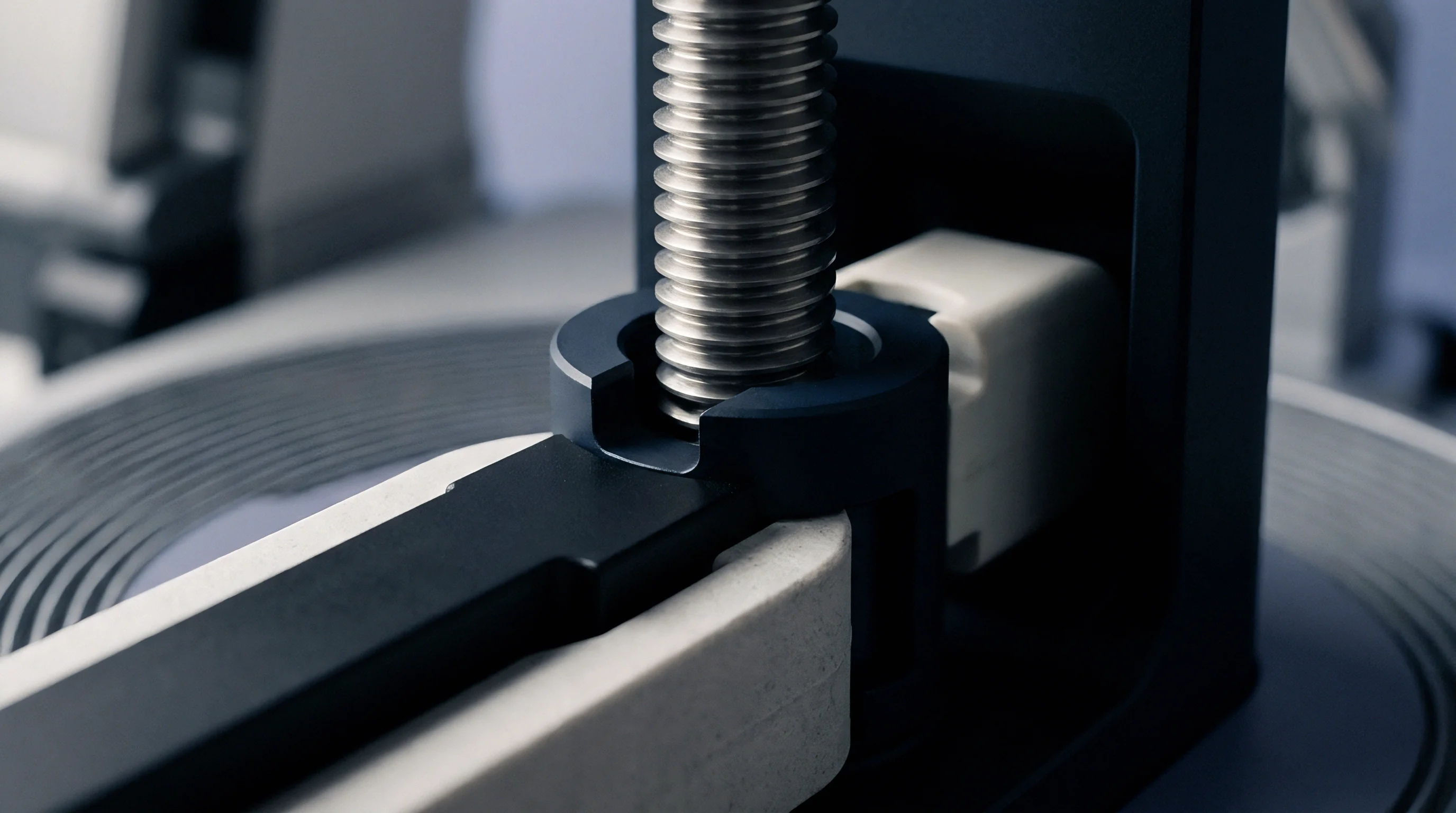
Installation requires the sensor diaphragm to sit flush with the cavity wall; a recess of just twenty micrometers creates a dead spot where polymer freezes, delaying signal response and distorting pressure peaks.
Transducer Selection and Installation Architecture
Direct-measuring transducers touch the melt directly, responding in less than a millisecond. They withstand continuous temperatures up to four hundred degrees Celsius and peak pressures of three thousand bar. Indirect transducers rest beneath ejector pins outside the cavity, recording force transmitted through the pin.
While indirect sensors avoid leave-behind witness marks on parts and simplify tool modification, they introduce frictional hysteresis and clearance errors from pin flex and thermal expansion.
- Machining Sensor Cavities Precision wire electrical discharge machining creates transducer mounting pockets with dimensional tolerances held within plus or minus five micrometers to prevent sensor body distortion under clamp tonnage.
- Wiring Signal Conductors High-impedance mineral-insulated coaxial cabling routes charge signals away from mold split lines, protected inside milled steel channels to shield sensitive pico-Coulomb currents from machine electromagnetic interference.
- Calibrating Charge Amplifiers Multi-channel signal conditioners establish zero-point balance and calibrate scale factors corresponding to individual transducer sensitivity certificates before thermal cycling begins.
- Validating Signal Response Impact testing on ejector pins verifies output linearity across the full operating force spectrum prior to closing the mold for production qualification runs.
Monitoring the noise floor across signal channels prevents false triggers as the melt front enters the cavity. Signal conditioners must sample cavity pressure at a minimum of one kilohertz to catch the fast pressure spikes that occur during the fill-to-pack transition. Filtering algorithms filter out mechanical vibration from clamp movement without phase-shifting the pressure curve, preserving timing accuracy for feedback loops.

Pressure Integral Derivation and Real-Time Signal Processing
Raw pressure-time curves from cavity transducers reflect the full molding history of each cavity. The pressure integral ~ the area under the curve from melt arrival through gate seal-off ~ measures the total energy delivered to the polymer in that impression. Differences in pressure integrals between cavities directly mirror variations in part mass, volumetric shrinkage, and critical dimensions.
Digital signal processors track the pressure gradient over time (dP/dt). A sharp upward break in dP/dt marks the moment polymer hits the transducer face, recording melt arrival at that point in the mold. Comparing arrival times across all sensors separates physical fill imbalance from overall injection speed changes.
If an inner cavity sensor registers melt arrival fifty milliseconds before an outer cavity sensor, the control system calculates the exact delay needed for dynamic valve gate timing.
Post-mold pressure curve matching software cannot compensate for poor mechanical tooling tolerances, as software adjustments fail to overcome the physical flow limits imposed by improperly sized gates.

Decoupling
Separating volumetric filling from hydraulic packing requires precise switchover points triggered by cavity pressure thresholds. Traditional decoupled molding uses screw position to switch from velocity-controlled filling to pressure-controlled packing at roughly ninety-five percent full. In complex multi-cavity molds, position alone cannot account for batch-to-batch viscosity shifts, regrind variations, or local mold temperature changes.
Using real-time cavity pressure signals turns static position switchover into dynamic, closed-loop decoupling based on real cavity conditions.
Dynamic decoupling uses the rapid pressure rise from key cavity transducers to signal the machine’s velocity valve or individual gate actuators. When the fastest-filling cavity hits a set threshold, the control system switches to packing mode or adjusts individual gate openings. This stops fast cavities from over-packing while slower ones finish filling, breaking the link between runner shear imbalances and part weight variation.

Hydro-Mechanical Separation of Fill and Pack
The transition from filling to packing is the most sensitive phase of the molding cycle. During filling, high injection speeds keep the melt front moving continuously. Switching to packing drops velocity sharply while pressure holds density against cooling shrinkage.
A late switchover causes severe pressure spikes in early-filling cavities, leading to tool deflection, flash, and stuck parts. Switching too early causes the melt front to hesitate, creating weld lines, sink marks, or short shots.
Per ISO 20457 specifications, dimensional tolerances across multi-cavity components require cavity peak pressure variations to remain inside a three percent spread band across the entire mold frame.
Dynamic valve gate timing allows independent control of melt delivery to each cavity impression. Pneumatic, hydraulic, or servo-electric stems inside the hot runner nozzles open and close based on real-time cavity pressure feedback. Holding stems shut on fast cavities while leaving them open on lagging ones balances melt delivery across the tool, regardless of runner shear imbalances.

Do Piezoelectric Sensors Resolve Viscous Shear Offsets?
Viscous shear offsets stem from non-Newtonian melt behavior in branched runners, creating localized viscosity variations that static runners cannot correct. In-cavity piezoelectric sensors measure the real-time pressure rise caused by these viscosity shifts as each cavity fills. Connected to an automated feedback system, cavity pressure signals dynamically adjust individual valve gate timing to correct for viscosity variations on every shot.
Closed-loop feedback adjusts individual gate opening delays relative to the start of injection. If an inner cavity fills early due to severe shear thinning, its pressure transducer registers the rapid pressure build and alerts the controller. The system then delays the gate opening for that cavity on subsequent shots, or throttles the stem to match the slower flow of outer cavities.
This real-time adjustment balances fill rates across all cavities without pulling the mold for physical runner re-machining.
- Thermal Drift Errors Temperature swings in hot runner manifolds alter pin clearances, introducing friction that skews valve gate opening times despite accurate control signals.
- Melt Degas Buildup Venting blockages cause localized gas counter-pressure, falsely inflating cavity pressure readings and triggering early gate closures on incomplete parts.
- Transducer Cable Noise Unshielded signal lines pick up electromagnetic interference from servo motors, causing false pressure peak triggers during high-speed injection.
- Valve Stem Wear Physical erosion of stem tips alters effective orifice areas, degrading volumetric flow rates despite consistent gate opening durations.
Comparing sensor placement near the gate with placement at the end of fill shows that end-of-fill positioning offers superior precision for triggering gate closure, while gate-adjacent placement works best for regulating pack pressure transmission.
Actuation Mechanics for Individual Gate Timing
Actuator response speed and repeatability set the limits for dynamic decoupling algorithms. Servo-electric valve gates allow precise position and velocity profiling, operating with microsecond response times and positioning accuracy within five micrometers. Pneumatic actuators cost less upfront but suffer from air compressibility delays and inconsistent response, adding timing jitter of over fifteen milliseconds.
Hydraulic gates deliver high force for large structural parts, but oil temperature shifts introduce timing drift.
Matching actuator technology to sensor speed determines overall performance. Servo-electric actuation allows partial throttling, moving the stem to intermediate positions rather than acting as a simple open-close switch. Throttling restricts flow into fast-filling cavities, keeping pressure gradients low across the runner tree while slower cavities catch up.
Running valve gates without position feedback risks pressure spikes that can damage mold surfaces.
Failing to verify mechanical zero-points on valve stems before enabling automated pressure control can permanently deform stem tips and damage nozzle seats.


Control
Real-time processing requires sub-millisecond, deterministic communication between cavity sensors and gate actuators. Standard industrial PLCs with scan times of five to twenty milliseconds add too much latency for high-speed injection. At fill speeds of three hundred millimeters per second, signal acquisition, algorithm execution, and output triggers must finish within a single millisecond to maintain screw position repeatability within fifty micrometers.
Dedicated FPGA hardware or real-time industrial PCs running fieldbus protocols like EtherCAT or PROFINET IRT manage the control loop. These systems sample incoming voltages, convert them to digital signals, filter noise, execute control algorithms, and fire valve drivers within sub-millisecond cycles. Deterministic timing ensures gate commands fire at exact intervals relative to cavity fill state, eliminating machine-driven process variation.
Closed-Loop Adaptive Feedback Algorithms
Standard PID routines struggle with injection molding because polymer filling is non-linear and discontinuous. Because molding runs shot by shot, continuous feedback adjustments cannot adapt fast enough within a single stroke. Advanced controllers combine Iterative Learning Control with Model Predictive Control to adjust parameters from one shot to the next.
Iterative Learning Control analyzes errors from previous shots to build feed-forward corrections for the next cycle. If Cavity 4 hits a peak pressure ten bar above target on shot N, the algorithm shortens its open time or restricts stem position on shot N+1. Model Predictive Control uses empirical rheological models to predict how pressure will respond to valve timing changes based on melt temperature, back pressure, and cycle stability.
| Control Loop Component | Hardware Architecture | Sampling / Execution Rate | Worst-Case Latency | Process Impact at 200 mm/s Fill |
|---|---|---|---|---|
| Analog Signal Acquisition | 16-bit ADC Module | 100 kHz | 10 microseconds | 0.002 mm melt front movement |
| FPGA Digital Signal Filtering | Direct Hardware DSP | 10 kHz | 100 microseconds | 0.020 mm melt front movement |
| EtherCAT Fieldbus Cycle | Industrial Ethernet | 1 kHz | 1.0 millisecond | 0.200 mm melt front movement |
| Standard PLC Scan Cycle | Main CPU Logic Loop | 100 Hz | 10.0 milliseconds | 2.000 mm melt front movement |
| Solenoid Valve Driver Response | High-Speed Solid State | 2 kHz | 0.5 milliseconds | 0.100 mm melt front movement |
Controller execution speed limits how well high-cavitation medical tools can be balanced when fill times drop below 0.3 seconds. Delays over two milliseconds allow uncorrected melt fronts to advance several millimeters, defeating real-time decoupling in thin-wall parts.
System calibration audits demand verifying deterministic fieldbus scan cycles below one millisecond to prevent valve actuation timing jitter under production loads.
Modifying the runner network in a 32-cavity tool cuts fill time variance across outer mold positions by 42 percent. System stability relies on predictable signal paths from transducer signal conditioners through control hardware to pneumatic switch valves. Mechanical wear in gate actuators, air pressure drops, and cable degradation introduce delays that disrupt closed-loop calculations.
Whether automated iterative learning algorithms can adapt to sudden viscosity jumps from irregular regrind additions without overshooting safety pressure limits in mass production remains an open question.

Validation
Statistical qualification establishes baseline capability across all impression locations. Quality standards typically require a Cpk above 1.33 for standard dimensions and 1.67 for critical safety parameters. Validating multi-cavity tooling requires treating each cavity as an independent process stream.
Pooling data across all cavities into a single global metric hides individual imbalances and gives a false picture of tool stability.
Initial validation starts with a short-shot study without pressure integration to establish the runner system’s native shear imbalance. Injection volume is increased incrementally from sixty to ninety-five percent fill, tracking part weights and visual progression across all cavities. Comparing weight distribution between inner and outer cavities isolates mechanical and rheological biases before activating automated dynamic decoupling.

Execution of Multi-Cavity Balance Qualification
Qualifying a multi-cavity tool equipped with cavity pressure sensors follows a step-by-step procedure to isolate hardware capabilities from process variables.
- Run native mechanical tool balance trials without cavity pressure feedback, documenting fill patterns from fifty percent to ninety-five percent volumetric fill across all cavity locations.
- Calibrate in-cavity pressure transducers, confirming signal linearity, zero-point stability, and temperature compensation across operating thermal ranges.
- Establish target cavity pressure integrals and peak pressure thresholds based on nominal dimensional compliance readings from single-cavity prototype evaluations.
- Engage dynamic decoupling control loops, adjusting iterative learning gain parameters until cavity pressure integrals converge within a three percent variance band across all cavities.
- Perform a consecutive fifty-shot process stability run, extracting pressure integral data, peak arrival times, and cycle times for automated statistical process control analysis.
- Measure critical dimensions across all harvested parts using automated coordinate measuring machines to verify correlation between pressure integrals and part tolerances.
Capability evaluation requires logging peak pressure, integral, and switchover values for every cavity on every shot. Statistical software then computes Cpk values for each cavity location independently. A tool meets qualification criteria only when its worst-performing cavity meets the required threshold.
Quality management standards specified under IATF 16949 Section 9.1.1 require multi-cavity statistical capability calculations to analyze each impression as an independent statistical sub-population.
Automated decoupling drops part weight variance across multi-cavity molds from over five percent down to under 0.3 percent. This consistency prevents over-packing, reduces internal stress, and tightens dimensional distributions across all cavities. Molders must re-validate sensor calibration and gate timing periodically to maintain stability over long production runs.
Under standard procurement terms, non-conformance claims for multi-cavity dimensional drift are unenforceable unless the buyer produces continuous, unedited cavity pressure log files for the production batch in question.


Economics
Calculating the payback for dynamic balance retrofits weighs capital expenditure against scrap reduction and shorter cycle times. Equipping a 32-cavity high-precision mold with cavity pressure sensors, fast valve actuators, and control hardware requires significant capital. Sensors, high-temperature cabling, amplifiers, and controllers represent substantial upfront costs, alongside the tool shop work needed to wire and mount hardware inside the mold.
Justifying the cost depends on savings over full production runs. Unbalanced multi-cavity tools force processors to lengthen cooling times and raise pack pressures to ensure outer cavities fill properly. Over-packing inner cavities adds component weight and wastes resin on every cycle.
Dynamic decoupling balances filling across the mold, allowing operators to drop pack pressures and shorten cooling times to save both material and cycle time.

Payback Analysis across Cavitation and Resin Cost Tiers
Financial returns depend heavily on cavitation count, annual volume, and material cost. Expensive engineering resins like PEEK or glass-filled nylon deliver quick payback through modest reductions in part weight. High-volume commodity molding benefits mostly from cycle time reduction and lower scrap rates.
| Tool Cavitation | Resin Type and Cost ($/kg) | Hardware & Retrofit CapEx ($) | Annual Resin Savings ($) | Scrap Reduction Savings ($) | Payback Period (Months) |
|---|---|---|---|---|---|
| 8-Cavity Structural | Polypropylene ($1.85) | 38,000 | 4,200 | 8,500 | 35.9 |
| 16-Cavity Automotive | PA66 GF30 ($5.20) | 62,000 | 18,400 | 24,100 | 17.5 |
| 32-Cavity Medical | Polycarbonate ($4.10) | 115,000 | 46,200 | 78,000 | 11.1 |
| 64-Cavity Closure | HDPE ($1.65) | 185,000 | 82,000 | 112,000 | 11.4 |
| 16-Cavity Aerospace | PEEK ($115.00) | 68,000 | 142,000 | 85,000 | 3.6 |
Scrap reduction is a primary source of savings. In high-cavitation medical tools, a single short shot or flashed part rejects the entire shot ~ scrapping all thirty-two or sixty-four components. Dynamic decoupling prevents localized defects caused by viscosity shifts or thermal swings, protecting first-pass yields.
Resin efficiency analysis confirms that eliminating over-pack in inner cavities reduces average part mass by up to two point four percent across high-cavitation tooling layouts.
Tooling maintenance drops under cavity-decoupled control. Lowering peak packing pressures reduces required clamp tonnage and cuts mechanical stress on split lines, core pins, and shutoffs. Preventing flash eliminates manual mold cleaning and avoids tool face damage from crushed plastic.
Hydraulic components also last longer when peak pressures drop during switchover.
Payback timelines scale predictably with resin costs, run hours, and baseline scrap rates. Integrating cavity pressure control turns multi-cavity molding from an empirical, open-loop process into a deterministically controlled manufacturing platform.