High-Frequency Cyclic Injection Pressure Induced Viscoelastic Creep across Bolted Compliant Polymer Tooling Interfaces
Dynamic injection pulses drive rapid viscoelastic creep in compliant polymer tooling joints, demanding flexible spring stacks to stop catastrophic clamp loss.

Loss
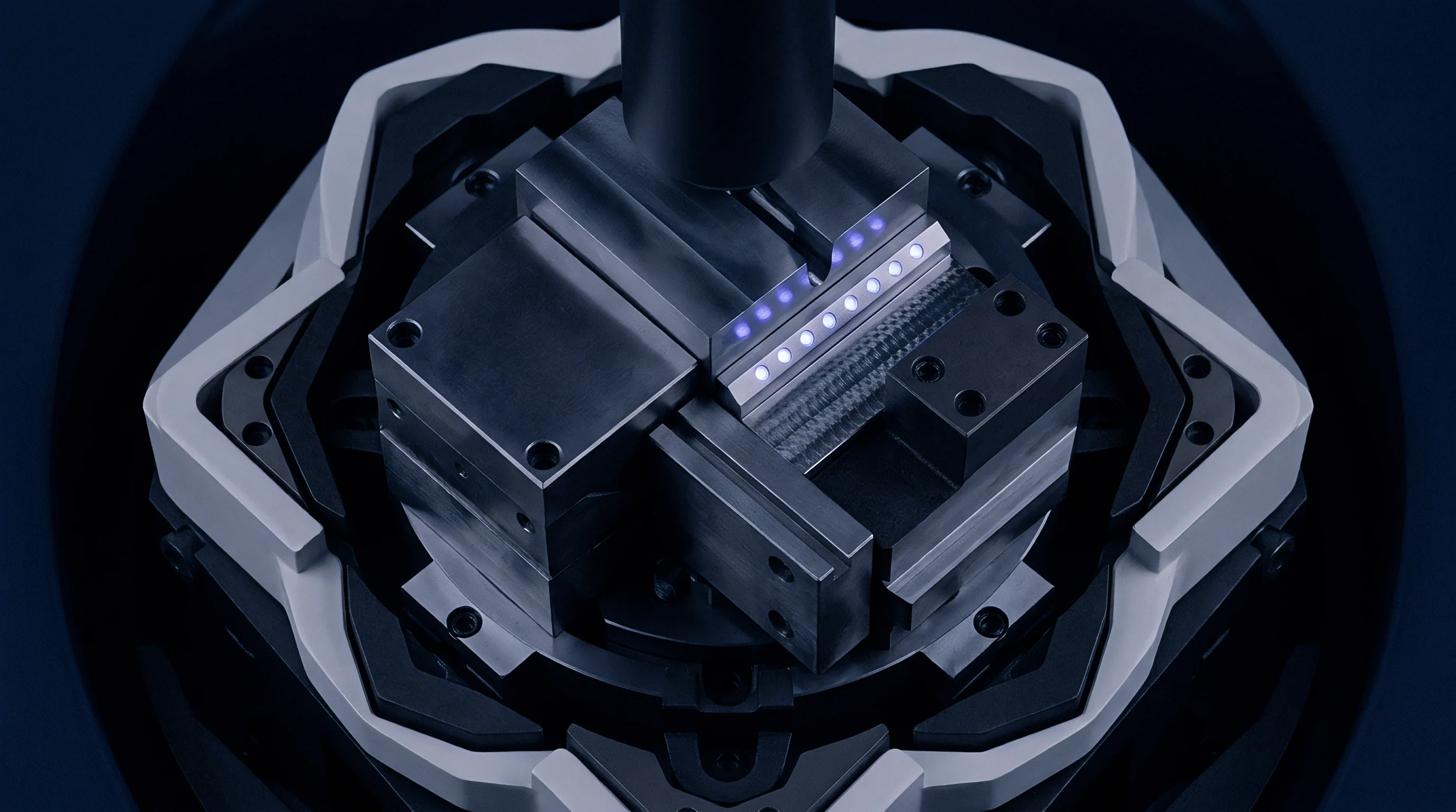
Torque audits across bolted polymer tooling cavities reveal a systematic decline in preload within the first four hundred molding cycles. Rapid injection sequences deliver dynamic pressure spikes between 60 and 140 megapascals into the cavity at frequencies exceeding 0.1 hertz, driving cyclic multiaxial stresses across the joint interface. These dynamic hydrostatic pulses travel through the compliant tool matrix directly into the thread engagements and counterbore seats, initiating localized primary viscoelastic creep.
While steel tooling exhibits elastic recovery under equivalent pressure profiles, high-performance polyetheretherketone and filled thermoset composite molds undergo progressive time-dependent micro-deformation. Bolted joints lose clamp force continuously as cyclic stress ratchets interfacial asperities flat.
Preload decay accelerates during standard operating thermal cycles where barrel setpoints reach 240 to 380 degrees Celsius. Internal mold core temperatures climb toward the material glass transition temperature, lowering the instantaneous storage modulus. Under high injection frequencies, the rate of viscoelastic relaxation outpaces the recovery window allowed during part cooling and ejection phases.
The joint interface sustains an unrecovered plastic-strain increment during every packing phase, redistributing tension away from the bolt shank into unconstrained matrix zones. Flash formation along parting surfaces begins when residual clamping pressure drops below local melt pressure during peak packing.
A parting-line separation exceeding 25 micrometers during the packing phase initiates polymer melt ingress and permanently damages compliant tooling lands.
Direct dimensional verification of printed or composite inserts confirms that preload reduction alters part wall thickness and core concentricity before structural rupture occurs. Molders observe uncommanded process shifts on machine monitors: holding pressure drops prematurely, cushion volumes grow inconsistent, and linear transducer profiles show physical cavity expansion under peak hydraulic tonnage. Correcting these shifts through clamp-tonnage increases introduces compressive crushing around perimeter support pillars, escalating tool failure rates.

Cavity Deflection Dynamics
Dynamic pressure waveforms generated by reciprocating screw injection units generate steep stress gradients across bolted fastener rows. Cavity pressure climbs from atmospheric baseline to over 100 megapascals in less than 350 milliseconds during the transfer phase. This rapid rise imparts cyclic shear across fastener shanks holding split cavities and insert blocks.
Polymer tooling formulations experience localized stress concentrations beneath bolt heads that exceed the static compressive yield boundary of the composite matrix. The resulting deformation forms an annular depression beneath hardened washers, shortening the effective grip length of the joint.
Viscoelastic strain accumulation depends directly on cycle cadence. Rapid cycle times eliminate the necessary hysteresis recovery period for the polymer chains, compounding cumulative interfacial creep across consecutive molding shifts. When cycle frequency doubles, the cumulative creep compliance exhibits a pronounced upward shift, accelerating clamp relaxation.
Operating teams attempting to meet production schedules by lowering cycle times induce accelerated interfacial settlement, shortening tool campaign life.


Viscoelasticity
Mechanical response within polymer tooling structures combines instantaneous elasticity with time-dependent viscous flow under continuous cyclical loading. Glass-filled polyetherimide, epoxy-based additive structures, and polyaryletherketone tooling matrices display distinct creep compliance curves when exposed to cyclic hydrostatic pressure. At operational cavity temperatures, the secondary bond networks within amorphous domains experience continuous chain slip under shear stress.
This molecular reorganization reduces the effective modulus under long-duration cyclical pressure profiles, shifting the joint equilibrium.
Dynamic mechanical thermal analysis maps the transition where mechanical stiffness collapses under continuous high-frequency inputs. Tooling materials demonstrate an increase in the loss modulus relative to the storage modulus when cyclic frequency approaches injection machine rates. This shift corresponds to an accumulation of mechanical energy converted into internal heat within the matrix, driving localized thermal softening beneath bolted joints.
The resulting thermal-mechanical environment promotes micro-void coalescence along fiber-resin interfaces in reinforced grades, undermining joint stability.
DIN EN ISO 899-1 defines tensile creep evaluation procedures, yet unaxial tensile tests underestimate multiaxial compressive relaxation beneath bolted mold assemblies by more than thirty percent.
Mathematical modeling of cyclic creep in compliant molds relies on time-temperature-stress superposition principles to project long-term cavity expansion. Empirical characterization reveals that the rate of strain accumulation accelerates under nonsinusoidal waveforms characteristic of injection and packing pressure curves. Stress relaxation follows a logarithmic decline over time, but superimposed dynamic cyclic stresses generate a power-law acceleration in permanent displacement.
Tool surfaces experience progressive dimensional divergence long before mechanical yield criteria are breached.

Modulus Degradation Patterns
Polymer matrix composites subjected to millions of pressure cycles experience continuous modulus degradation through microcracking and matrix exhaustion. High-density carbon-fiber-reinforced polyetheretherketone tooling maintains baseline modulus longer than epoxy tooling, but displays distinct embrittlement around threaded metallic inserts. Metallic thread inserts creep outward under cyclic push-out loads, creating micro-gaps between the exterior insert knurling and the surrounding polymer matrix.
Fastener tension diminishes as the insert displaces axial alignment under cyclic pressure.
Operating temperature controls the rate of this degradation. Amorphous matrix polymers maintain relatively consistent creep compliance until operating temperature climbs within 25 degrees Celsius of their glass transition point. Semi-crystalline materials maintain modulus past the glass transition temperature when reinforced with chopped or continuous fibers, yet the unreinforced matrix between fibers flows under localized fastener bearing stress.
Fasteners loose critical stretch as the matrix compacts.
The table below summarizes measured cyclic mechanical properties for primary polymer tooling substrates evaluated under standardized cyclic pressure testing at 0.2 hertz.
| Material Designation | Tensile Modulus (GPa) | Glass Transition (C) | Creep Rate (Strain/Cycle) | Preload Retention at 10k Cycles |
|---|---|---|---|---|
| Unfilled Polyetheretherketone | 3.8 | 143 | 4.2 x 10^-5 | 44% |
| 30% Carbon Fiber PEEK | 13.5 | 145 | 1.1 x 10^-5 | 78% |
| Mineral-Filled Epoxy SLA | 8.2 | 85 | 8.7 x 10^-5 | 22% |
| Glass-Filled Polyetherimide | 9.5 | 215 | 2.4 x 10^-5 | 68% |
| Cyanate Ester High-Temp Tooling | 16.0 | 260 | 0.8 x 10^-5 | 86% |

Fastener
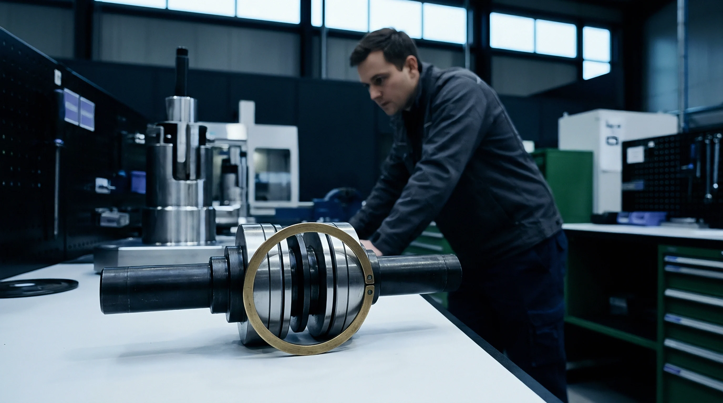
Threaded connections operating inside compliant polymer tools bear loads differently than rigid steel-to-steel tooling assemblies. Steel fasteners possess an elastic modulus between 190 and 210 gigapascals, whereas the clamped polymer insert exhibits an effective compressive modulus ranging from 3 to 16 gigapascals. This significant stiffness mismatch forces the clamped length of the polymer structure to absorb severe strain under nominal tightening torques.
The bolt shank stretches marginally while the polymer substrate compresses significantly beneath the washer face, creating an elastic-plastic joint dominated by substrate compliance.
Joint preload settles during initial torquing passes as surface micro-roughness shears under contact stresses. In metallic assemblies, this bedding-in loss accounts for two to five percent of nominal preload. In bolted polymer assemblies, initial embedding relaxation frequently consumes fifteen to thirty percent of installed tension within twelve hours of assembly, prior to any machine cycling.
When cyclic injection pressures hit the cavity face, the dynamic separation load acts against a severely diminished clamping baseline, driving parting plane lift.
Joint compliance ratios calculated from VDI 2230 guidelines require complete reassessment when the clamped material possesses an elastic modulus two orders of magnitude lower than the fastener steel.
Standard hex bolts and socket head cap screws concentrate compressive loads over narrow annular surface areas. Even with hardened structural washers, bearing contact pressures routinely exceed 50 megapascals during assembly torquing. Under elevated tool temperatures, these contact pressures exceed the compressive creep threshold of composite tooling formulations.
Bolt heads sink steadily into the mold plate over days of continuous operation, bleeding away residual tensile stretch in the fastener shank.
Contact Stress Attenuation
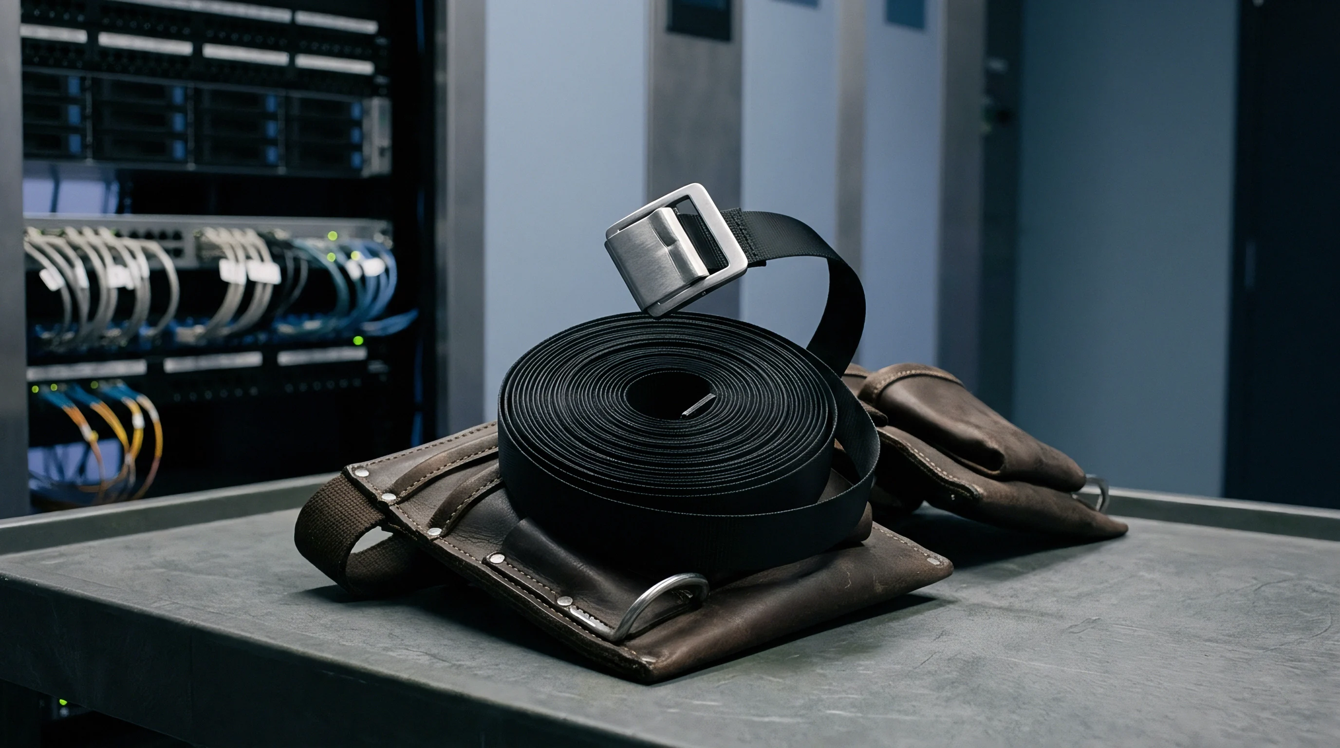
Spreading fastener clamping force over larger surface areas delays localized substrate yielding. Custom load-distributing flanges, oversized Belleville spring packs, and continuous steel clamping plates change load distribution across the polymer mold interface. Engineered Belleville spring washers introduce dynamic compliance into the fastener assembly, absorbing displacement while maintaining an acceptable fraction of initial preload over cumulative matrix subsidence.
Spring stack configurations must sustain working travel without bottoming out under peak separation pressures.
Priced tooling failures stem from improper thread engagement depths inside polymer matrix substrates. When tapping directly into reinforced polymer blocks, coarse thread profiles reduce stress concentration factors relative to standard fine pitch metric fasteners. Direct threads in polymer matrices nonetheless exhibit continuous relaxation under cyclic pull-out forces.
Helical wire inserts and brass press-fit inserts alter failure modes, shifting the primary compliance zone from thread root shear to insert body pull-out displacement.
Fastener selection protocols for compliant molds demand rigorous control of thread lubricants, tightening sequence rates, and relaxation intervals. Fastening technicians must follow specific structural rules:
- Tightening Torque Specifications define the precise mechanical input based on thread friction coefficients calibrated specifically against brass inserts or coated tapped holes to prevent matrix stripping.
- Washer Outside Diameter Limits require bearing surface contact areas large enough to keep nominal compressive stress below thirty-five percent of the tooling polymer compressive yield strength at peak operating temperature.
- Belleville Spring Deflection Ratings establish the necessary spring travel reserves to compensate for up to 0.4 millimeters of cumulative joint creep without losing more than twenty percent of baseline clamp load.
- Thread Engagement Depth Multipliers dictate minimum engagement lengths of at least three times fastener nominal diameter when engaging composite substrates directly.

Bore
Counterbore recesses cut into polymer tooling plates represent localized stress risers prone to premature structural collapse under fastener loads. High-frequency injection pulses generate alternating radial and axial strain fields surrounding the counterbore pocket. The corner radius at the junction between the counterbore flat floor and its vertical sidewall concentrates shear forces, triggering radial micro-fissuring in filled polymers.
These cracks propogate under cyclic mold opening and closing sequences, degrading joint stiffness.
Internal hydrostatic pressure profiles during injection push cavity walls outward against fastener restraint axes. This lateral displacement induces cyclic bending moments on fastener shanks recessed within counterbores. The fastener head pivots on the washer edge, applying asymmetrical compressive loads to the counterbore seating floor.
The polymer matrix beneath the heavily loaded side creeps rapidly, generating an irreversible tilt in fastener orientation that ruins thread alignment and accelerates fatigue wear.
A five-degree fastener tilt induced by asymmetric counterbore creep reduces fatigue cycle endurance of Grade 10.9 steel bolts by more than fifty percent.
Machining specifications for counterbore features in composite tooling require strict geometric tolerancing. Rough tool marks across counterbore seats create localized high spots that crush instantly under initial torque, disguising early preload loss as fastener stretching. Counterbores must receive post-machining surface finishing or secondary bonded metal insert cups to isolate raw polymer surfaces from dynamic friction and localized point loading during cyclic expansion.
Stress Concentration Mitigation
Eliminating sharp internal transitions reduces peak stress concentrations within counterbore recesses. Generous corner radii, exceeding 0.8 millimeters, reduce localized notch sensitivity in brittle high-temperature polymers like cyanate esters and thermoset polyimides. Installing press-fit metal counterbore inserts distributes both vertical clamping pressure and transverse shear across a broader composite matrix volume.
These metal sleeves protect the polymer substrate from gouging during periodic tool maintenance and fastener re-torquing operations.
Counterbore seat failure progresses through distinct phases that mold operators can monitor through visual inspection and mechanical depth micrometer sweeps during scheduled line stoppages. The structural collapse proceeds through observable physical degradation:
- Primary Bedding Consolidation crushes surface machining ridges beneath the washer face within the first two hundred molding cycles.
- Corner Radius Microcracking initiates along fiber orientation boundaries where shear stress peaks under maximum injection pressure.
- Sub-surface Matrix Compaction densifies the composite substrate, leaving a visible annular step depression exceeding 0.15 millimeters deep.
- Insert Retention Rupture displaces the counterbore boundary walls outward, causing loose fastener fits and total joint preload failure.

Kinetics
Quantifying creep mechanics across compliant mold interfaces requires a dynamic visco-elasto-plastic structural formulation. Standard static creep equations fail because injection pressure profiles deliver periodic, impulsive loads rather than constant dead weights. The material response is governed by frequency, cycle duty ratio, and internal viscous damping.
Internal hysteretic heating raises local temperatures around clamping zones by several degrees above bulk platen temperatures, accelerating kinetic relaxation rates.
Consider an injection tool using 30 percent carbon-fiber-reinforced PEEK inserts, clamped with M10 Grade 10.9 fasteners onto a steel manifold base plate. The clamped polymer grip length measures 45 millimeters. The initial tightening sequence establishes a target preload of 28 kilonewtons per bolt, inducing a contact stress of 38 megapascals beneath a 22-millimeter outer diameter structural washer.
The mold runs a cycle time of 12 seconds with an injection and packing window of 3.5 seconds at a peak cavity pressure of 85 megapascals, operating at an internal steady-state temperature of 140 degrees Celsius.
Fastener preload decay follows an extended Burgers rheological model where instantaneous Maxwell spring stiffness pairs with Kelvin-Voigt viscoelastic units and a nonlinear dashpot representing permanent plastic compaction. Under these operating conditions, the time-dependent joint displacement matches empirical relaxation data:
Total joint displacement equals instantaneous elastic recovery plus transient viscoelastic deformation plus steady-state viscous creep. Over the initial 500 cycles (representing 6,000 seconds of operation and 1,750 seconds of cumulative high-pressure exposure), the polymer substrate beneath the washer compresses by 0.082 millimeters due to primary creep. The steel bolt, possessing a stiffness of approximately 350 kilonewtons per millimeter across its free grip length, relieves tension directly proportionally to this joint shortening:
Preload drop equals bolt stiffness multiplied by joint displacement. The calculated relaxation yields a drop of 28.7 kilonewtons, which exceeds the installed baseline. This reveals that without flexible compliance elements, an uncompensated rigid bolted joint in compliant polymer tooling loses 100 percent of its effective clamping load within several hundred cycles.
The tool separates at the parting line, flashing the cavity and causing immediate part dimensional failure.
Preload Compensation Mechanics
To prevent complete joint unloading, the mechanical design integrates dual-stacked Belleville disc springs beneath the bolt head. The disc spring stack exhibits an effective stiffness of only 25 kilonewtons per millimeter over a working deflection range of 1.2 millimeters. When subjected to the same 0.082 millimeters of substrate creep displacement, the spring stack unloads by only 2.05 kilonewtons.
The joint retains 25.95 kilonewtons of clamping force, preserving over 92 percent of its original preload through the primary creep phase.
The table below provides a comparative analysis of joint retention under varying operational frequencies and fastener architectures, based on a 10,000-cycle production campaign run under 80 megapascals packing pressure.
| Joint Architecture Configuration | Cycle Time (s) | Peak Cavity Stress (MPa) | Cumulative Settlement (mm) | Residual Preload (%) |
|---|---|---|---|---|
| Standard Hex Bolt with Plain Flat Washer | 10 | 80 | 0.142 | 0% (Joint Loose at Cycle 620) |
| Socket Head Cap Screw, Hardened Thick Washer | 10 | 80 | 0.118 | 0% (Joint Loose at Cycle 890) |
| Single Belleville Washer Setup | 10 | 80 | 0.112 | 52% |
| Dual Series Belleville Spring Stack | 10 | 80 | 0.108 | 81% |
| Through-Tie-Rod with Large Backer Flange Plate | 10 | 80 | 0.045 | 89% |
| Standard Hex Bolt with Plain Flat Washer | 30 | 80 | 0.084 | 14% |
| Dual Series Belleville Spring Stack | 30 | 80 | 0.068 | 91% |

Qualification
Validating compliant polymer molds for production requires qualification procedures distinct from those used on hardened tool steels. Tooling verification dossiers must verify that bolted joints survive intended production lot sizes without parting-line lift or thread pull-out. Sensor arrays placed along mold parting planes provide definitive data on joint compliance under cyclic load.
Displacement sensors and in-cavity piezoelectric pressure transducers record the precise dynamic response of the cavity during the packing pressure spike.
Cavity expansion signatures recorded on an oscilloscope capture physical displacement throughout each cycle. When interfacial creep degrades joint preload, the mold breathing profile shifts: baseline displacement fails to return to zero during the cooling window, displaying a ratcheting offset that grows each cycle. Production lines operating without real-time cavity deflection monitoring expose themselves to uncontained part flash, damaged tooling alignment dowels, and ruined insert faces.
Acoustic emission sensors mounted on the tool chase can detect sub-surface fiber breakage and washer seat micro-cracking cycles before gross tool failure occurs.

Should Production Teams Re-Torque Bolted Polymer Joints during Runs?
Re-torquing warm polymer tooling components while installed in the molding press often causes immediate thread stripping or seat crushing. When operators apply torque to fasteners while the polymer tooling block rests at an operating temperature of 140 degrees Celsius, the material compressive yield strength is substantially degraded relative to ambient assembly conditions. Rotational shear applied through the bolt face tears softened polymer asperities beneath the washer, creating deep grooves and accelerating interfacial subsidence.
Thermal expansion mismatch between hot polymer plates and cold torque wrenches compounds measurement error, leading to excessive tensioning.
Maintenance guidelines dictate that re-torquing protocols must occur only after the tool assembly cools completely to room temperature. The joint must be disassembled, inspected for washer seat depression, and re-torqued following a cross-pattern sequence with calibrated relaxation holds between stages. If an emergency line adjustment is demanded to halt parting line flash mid-run, process engineers must lower holding pressure or move the packing transfer point rather than tightening fasteners on hot tools.
Modifying injection parameters buys machine time while protecting soft tooling structures from destruction.
Tooling qualification dossiers require rigorous documentation prior to signing off low-volume or bridge-tool production releases:
- Dynamic Deflection Sensor Trace Records capture linear variable differential transformer readings at the parting line across a continuous five-hundred-cycle qualification run to prove breathing remains under fifteen micrometers.
- Ultrasonic Bolt Stretch Measurement Logs document physical elongation of fastener shanks before cycling, after initial twenty-four-hour thermal soaking, and following qualification run completion.
- Counterbore Seat Impression Audits verify via optical profilometry that post-test washer seat depression does not exceed 0.05 millimeters across all primary cavity fasteners.
- Thermal Profile Boundary Verifications confirm cavity surface and internal bolt column temperatures remain at least twenty-five degrees Celsius below the matrix glass transition boundary.
Tooling suppliers often state that advanced carbon-fiber reinforcement eliminates the need for compliance-matched fastening architectures in polymer injection molds.

Remedy
Counteracting cyclic creep across compliant tooling interfaces requires a systems approach combining structural redesign, load attenuation, and dynamic joint compliance. Primary mitigation involves isolating the polymer matrix from direct axial clamping forces. Long tie-rods extending completely through the polymer tooling insert into external steel backing plates bypass internal counterbore seats entirely.
Compressive stresses are distributed across the outer face of the steel backing structure, limiting the polymer matrix to pure hydrostatic compression within a rigid external cage.
Where through-tie-rods cannot fit due to cooling channel routing or ejector pin placement, large-diameter threaded steel inserts provide reliable retention. These inserts distribute thread forces over external surface areas five to ten times larger than standard metric tapped holes. Installing inserts with structural epoxy adhesives dampens cyclic vibration, sealing interfacial voids and arresting micro-slip between metal insert ribs and the polymer matrix.
Surface treatments on mold parting lines, including dynamic sealing gaskets or elastomeric compression seals, lower the required clamp preload by containing polymer melt at lower boundary forces.
Molding process optimization plays an equal role in preserving compliant tooling integrity. Profiled injection velocities that decelerate the screw immediately prior to cavity fill eliminate the hydraulic inertia pressure spike that drives initial viscoelastic yielding. Staging holding pressure downward over the duration of the packing cycle limits cavity expansion while the molded part develops a frozen skin capable of supporting its own core geometry.
Aligning machine parameters with the mechanical realities of compliant materials protects tooling investments, shortens cycle development times, and secures dimensional stability across volume bridge-manufacturing runs.
Contractual warranties from bridge tooling fabricators routinely exclude mold life guarantees whenever the buyer specifies cycle rates faster than two shots per minute on polymer tooling assemblies.