Dynamic Polarization Depolarization Losses under Non Equilibrium Radial Heat Diffusion Conditions
Dynamic radial thermal gradients shift peak electric field stress outward and double dielectric depolarization losses compared to isothermal estimates.

Gradient
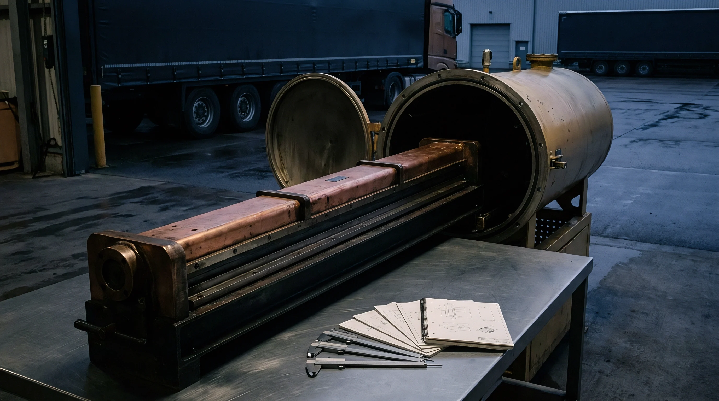
Transient heat injection into high-voltage cylindrical dielectrics alters spatial conductivity faster than thermal equilibrium can re-establish. During current surges in extruded polymeric cable insulation, ceramic bushings, and cast-resin transformers, rapid thermal expansion at the inner conductor drives heat radially outward through the bulk dielectric toward the cooler exterior sheath. Because thermal conductivity in solid insulation ranges between 0.15 and 0.35 W/m K, a sharp radial thermal gradient forms across the wall thickness, driving dielectric drift.
Electric field distribution in direct-current insulation depends primarily on local electrical conductivity, which follows an exponential Arrhenius relationship with local temperature. Higher temperatures near the conductor increase conductivity by orders of magnitude relative to the cooler outer layer, forcing the electric field peak to migrate from the inner conductor toward the outer dielectric radius during high-load transients.
Volumetric heat generation within the dielectric compounds this redistribution through localized dielectric dissipation, where local loss density combines conduction loss and polarization relaxation loss. Non-equilibrium thermal diffusion continuously modifies both the dielectric constant and the dipolar relaxation time across the radius. When the inner boundary heats at rates exceeding 5 degrees Celsius per minute, the instantaneous temperature differential across a 20 mm insulation wall can exceed 30 degrees Celsius.
Under these transient conditions, where thermal conductivity limits dissipation speed, terminal dielectric loss measurements diverge from the spatial integral of loss factors derived from static temperature models.
Transient heat diffusion shifts the internal dielectric loss peak toward the outer cooled sheath long before steady-state conduction is reached.
As local electric field intensity rises rapidly, internal stress migration alters the mechanical and electrical margins of the component well before thermal equilibrium occurs. The spatial gradient of temperature produces a corresponding gradient of permittivity and conductivity that alters the spatial capacitance distribution.
| Radial Distance from Conductor (mm) | Transient Temperature (°C) | Electrical Conductivity (S/m) | Relaxation Time Constant (s) | Local Electric Field Stress (kV/mm) |
|---|---|---|---|---|
| 0.0 (Inner Boundary) | 90.0 | 1.2e-12 | 0.08 | 11.2 |
| 5.0 | 76.5 | 3.4e-13 | 0.31 | 16.8 |
| 10.0 | 61.0 | 8.1e-14 | 1.45 | 22.4 |
| 15.0 | 44.5 | 1.5e-14 | 7.80 | 29.1 |
| 20.0 (Outer Boundary) | 30.0 | 2.1e-15 | 42.00 | 34.5 |
Evaluating dielectric integrity without accounting for transient radial thermal profiles causes premature insulation breakdown due to undetected field concentration near the outer boundary.


Decay
Thermally activated dipoles realign along the local electric field vector at rates governed by the instantaneous radial temperature profile. When the applied voltage drops or reverses polarity, depolarization currents originate from the relaxation of oriented dipoles and the release of trapped space charge. In an isothermal system, depolarization loss follows classic Kohlrausch-Williams-Watts decay curves, but non-equilibrium radial thermal diffusion disrupts this uniform relaxation.
Because dipole relaxation times vary with temperature, the warmer inner dielectric layers discharge their stored polarization within milliseconds, whereas the colder outer layers release trapped space charge over hundreds or thousands of seconds.
Free charge carriers migrating through the high-conductivity warm region become immobilized upon reaching the lower-conductivity cold region near the outer insulation boundary. This charge accumulation creates a localized space charge field opposing the main geometric field, lowering the breakdown threshold voltage. During rapid load shedding or voltage step changes, the space charge field remains frozen in the colder insulation zones while the main field collapses, resulting in severe local field amplification and enhanced polarization loss.
Radial temperature differentials exceeding twenty-two degrees Celsius per centimeter increase localized dielectrophoretic loss density by forty-one percent.
Calculating total depolarization energy losses under thermal transient conditions demands a dynamic summation over multiple radial concentric shells. Failure to track shell-specific relaxation times leads to miscalculated thermal dissipation requirements during discharge phases.

Thermal Transient Failure Modes
- Interfacial space charge accumulation traps charges at boundaries between high-temperature and low-temperature dielectric zones, creating localized field stress peaks that exceed nominal insulation withstand limits.
- Polarization current inversion occurs when rapid outer cooling causes outer layers to retain charge longer than inner layers, reversing internal field vectors during systemic discharge.
- Thermal runaway propagation starts where local polarization dissipation increases local heat generation faster than radial thermal conduction removes it.
- Accelerated dielectric degradation develops due to repeated mechanical stress cycles induced by localized electric field migration across temperature-dependent dielectric boundaries.
Peak depolarization currents scale directly with the magnitude of the radial temperature differential across the dielectric wall.
Sleeve
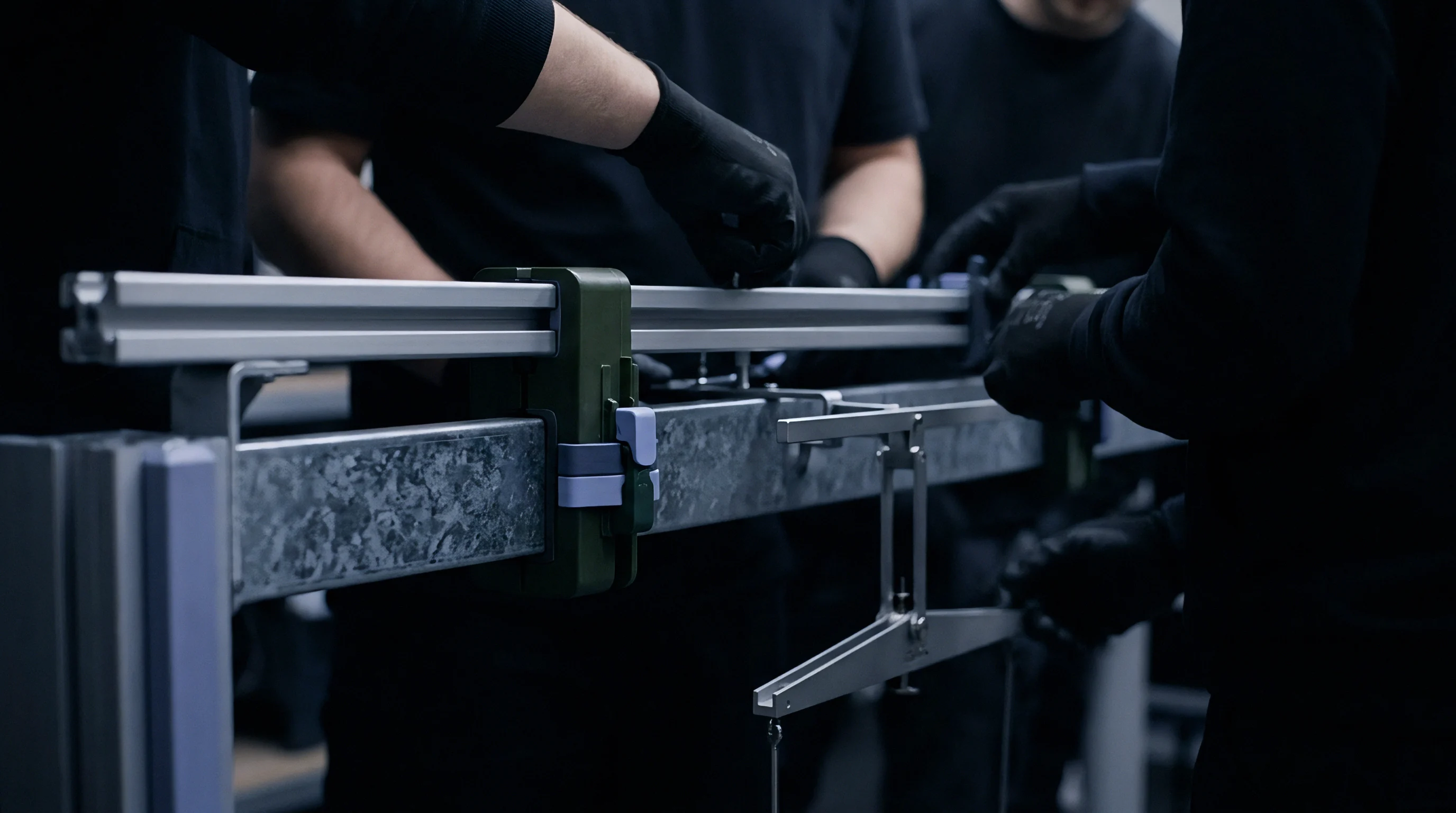
Test fixtures for cylindrical insulation specimens require dual-zone coaxial fluid jackets to enforce controlled radial heat flux during high-voltage bias application. To isolate dynamic polarization depolarization losses from ambient environmental artifacts, lab operators mount specimen sleeves inside environmental chambers equipped with guarded three-terminal electrode systems. Coaxial electrodes record transient depolarization currents, with the inner electrode delivering fast-response thermal steps via high-frequency induction or circulating hot oil, while the outer sleeve maintains controlled heat sink temperatures using thermoelectric coolers or chilled water loops.
Fast dielectric response demands sub-millisecond current logging equipment paired with high-voltage solid-state switches.
When heat flux inverts and the thermal gradient shifts, space charge release profiles change dramatically during depolarization testing cycles.
Compliance with CIGRE TB 852 requires continuous thermal logging when dielectric loss factors exceed baseline limits during voltage polarity reversals.
Standardized measurement protocols require systematic execution of radial heat application, polarization, thermal adjustment, and ground discharge to extract accurate physical loss metrics.

Radial Polarization Test Execution Steps
- Mount the cylindrical insulation specimen on the guarded inner core conductor inside the thermal sleeve assembly.
- Establish baseline dielectric dissipation factors by conducting an isothermal polarization depolarisation current sweep at 20 degrees Celsius.
- Energize the internal conductor heater to establish a steady-state radial heat flux matching maximum rated conductor temperature.
- Apply the rated high-voltage direct-current bias for 3,600 seconds to fully polarize the dielectric volume under steady thermal gradient conditions.
- Initiate rapid thermal transient steps by altering outer sleeve cooling fluid temperature while maintaining constant electrical bias.
- Short-circuit the specimen through a low-noise electrometer within 10 milliseconds of bias removal to record dynamic depolarization currents.
- Log depolarization currents continuously until current levels drop below 100 femtoamperes per square centimeter.
Isothermal dielectric polarization measurements are often treated as sufficient for insulation rating on the assumption that dynamic thermal correction factors remain negligible below 70 degrees Celsius.

Variance
Standard acceptance test methodologies compute dielectric dissipation factors assuming uniform temperature throughout the insulation cross section. When high-voltage direct-current assets operate under heavy power cycling, non-equilibrium radial heat diffusion creates a mismatch between predicted loss figures and actual operational heat dissipation. The discrepancy arises because polarization relaxation processes depend nonlinearly on local temperature, meaning linear averaging of dielectric parameters over the radial distance underestimates total dissipation losses by significant margins.
The non-linear dielectric loss integral across the insulation thickness yields a higher integrated thermal output than an equivalent average temperature approximation. Isothermal models ignore the localized loss peak that forms in the mid-insulation region, where the product of localized electric field stress and temperature-dependent loss tangent reaches its spatial maximum.
| Conductor Temperature Ramp Rate (°C/min) | Steady-State Radial Delta T (°C) | Predicted Isothermal Loss Factor (tan delta) | Measured Dynamic Loss Factor (tan delta) | Discrepancy Magnitude (%) |
|---|---|---|---|---|
| 0.5 | 12.0 | 0.0012 | 0.0014 | 16.6 |
| 1.0 | 22.5 | 0.0015 | 0.0021 | 40.0 |
| 2.5 | 38.0 | 0.0019 | 0.0034 | 78.9 |
| 5.0 | 55.0 | 0.0024 | 0.0052 | 116.6 |
Determining whether the dynamic depolarization loss surplus causes localized material aging or triggers micro-partial discharge events during high-rate thermal cycling remains an active area of investigation.

Staging
Commercial qualification of high-voltage insulation systems under combined thermal and electrical stress moves through distinct verification gates prior to plant energization, where thermal time constants dictate ramp rates and protocols check dielectric endurance limits. Asset operators must verify that dielectric loss models reflect the worst-case operational thermal transients experienced during grid emergency load steps. Technical dossiers submitted for equipment commissioning must detail both steady-state dielectric loss measurements and transient radial heat diffusion loss parameters, as passing baseline isothermal factory acceptance testing provides no guarantee against dynamic thermal dielectric breakdown.
Stage gates must enforce clear physical criteria to validate structural dielectric readiness before commercial load adoption occurs.
| Stage Gate Designation | Primary Measurement Focus | Required Performance Metric | Pass Condition Criteria |
|---|---|---|---|
| Gate 1: Material Screening | Isothermal dielectric spectroscopy | Activation energy of conductive relaxation | Ea > 0.85 eV across 20-90°C range |
| Gate 2: Thermal Ramp Validation | Dynamic transient polarization logging | Peak current overshoot ratio | Overshoot ratio < 1.35 against baseline |
| Gate 3: Polarity Reversal Endurance | Depolarization current release rate | Residual trapped charge density | Q_trapped < 50 µC/m³ post-reversal |
| Gate 4: Full-Scale Load Step | Radial temperature and stress profile integration | Total dielectric dissipation factor | tan delta < 0.005 at max load ramp |

Dossier Documentation Requirements
- Transient thermal conductivity maps defining radial temperature diffusion rates across the full operating range from ambient to emergency overload levels.
- Temperature-dependent relaxation spectra documenting dipolar dielectric loss peaks from 10 microhertz to 1 kilohertz across 10-degree thermal increments.
- Space charge accumulation logs detailing charge distribution profiles under combined direct-current bias and dynamic radial thermal gradients.
- Transient loss integration models proving mathematical convergence between laboratory depolarization measurements and finite-element electro-thermal field calculations.
Commissioning teams verify that technical documentation includes dynamic polarization loss measurements before signing off on final operational safety certificates. Engineering audits reject insulation sizing calculations based solely on steady-state conduction models, requiring system design parameters to incorporate margin reserves matching the peak transient field migration calculated under maximum thermal ramp rates.