Dynamic Clamping Force Control in Polymer Insert Tooling Nests
Dynamic clamping force control synchronizes tonnage to melt pressure, preventing parting flash while shielding polymer inserts from compressive destruction.
Seat
Rigid steel master unit dies deform polymer inserts when hydraulic presses apply conventional tonnage. Production lines running stereolithography or high-temperature thermoset cavities face localized plastic collapse during the initial ten cycles if clamp forces stay locked at full press capacity. The elastic modulus of cured ceramic-filled tooling resins hovers between 4 and 8 gigapascals, whereas standard P20 tool steel exhibits 205 gigapascals.
Clamping a 100-tonne platen across a tooling pocket containing soft polymer blocks induces compressive strains exceeding 2.5 percent across the parting perimeter. Steel chases restrict lateral expansion, forcing the polymer matrix to bulge into unsupported cavities or crush micro-vent channels. Insert longevity collapses before completing pilot validation runs.

Polymer Nest Compliance under Load
Tooling pockets machined into standard mold bases absorb clamping loads through direct surface contact. When an injection press applies a static closing load of 800 kilonewtons across four polymer inserts, contact stress distributions diverge from metal-to-metal tooling assumptions. Viscoelastic creep initiates immediately upon platen contact.
The compressive stress under initial touch reaches 32 megapascals at 23 degrees Celsius. At elevated cavity temperatures of 85 degrees Celsius, the compressive yield strength drops by 45 percent, inducing non-recoverable dimensional displacement. Tooling pockets must seat the insert with precise interference tolerances to prevent perimeter extrusion while avoiding edge shearing.
Low-modulus tooling inserts experience 0.08 millimeters of axial compression under 400 kilonewtons of clamp load at 65 degrees Celsius.
Axial displacement creates mismatch steps along runner transitions and core shut-offs. Melt channels positioned across the steel-to-polymer split plane misalign by up to 0.12 millimeters under unmodulated clamping forces. This step creates localized shear heating, premature gate freeze, and pressure spikes during polymer injection.
Tooling engineers adjust static tonnage downward to protect the polymer blocks, yet this adjustment triggers gross parting-line flash as injection pressure peaks during cavity filling. Static clamping forces fail to reconcile insert preservation with cavity containment.
Uncontrolled pre-clamping crushes delicate internal shut-off lands, rendering replacement of the printed blocks unavoidable within sixty moulding shots.
Transducer
Instrumentation arrays embedded behind the mold nest capture real-time compressive kinetics during each machine cycle. Piezoelectric quartz load washers positioned beneath the backing plates measure transient force distribution across individual cavity blocks with response times below 0.5 milliseconds. Tie-bar strain gauges read overall machine frame elongation, whereas pocket-level sensors isolate local insert deflection.
Combining tie-bar force readings with local nest load cells allows the machine controller to detect non-parallel platen movement down to 0.005 millimeters per meter. Electric servo drives on modern toggle presses modulate tie-bar strain within 12 milliseconds of receiving local threshold triggers.

Sensor Deployment in Tooling Pockets
Pocket-level instrumentation isolates thermal expansion strains from direct hydraulic mechanical pressure. Piezoelectric quartz force rings install directly behind hardened backup shims behind each polymer cavity nest. Grounding isolation rings isolate high-impedance cabling from machine frame static charges.
Fiber-optic pressure sensors installed inside the runner system deliver simultaneous melt pressure values to the controller bus. Signal conditioning amplifiers convert picocoulomb charges into 0-to-10 volt analog signals sampled at 2 kilohertz. The controller calculates real-time net cavity opening forces by integrating projected cavity area against transient melt pressure curves.
| Transducer Mechanism | Measurement Axis | Sampling Rate | Calibration Drift Rate | Working Temperature Range |
|---|---|---|---|---|
| Quartz Load Washer | Axial Pocket Force | 2.5 kHz | 0.02% per 10,000 cycles | -20 to 120 °C |
| Tie-Bar Strain Gauge | Total Machine Force | 1.0 kHz | 0.15% per 5,000 cycles | 10 to 60 °C |
| Cavity Pressure Pin | Melt Normal Force | 5.0 kHz | 0.05% per 10,000 cycles | 20 to 220 °C |
| Eddy-Current Displacement | Parting Separation | 4.0 kHz | 0.08% per 8,000 cycles | 0 to 100 °C |

Closed-Loop Servo Hydraulic Response
Platen hydraulic circuits require high-speed proportional valves to bleed off excess tonnage during injection packing transitions. Standard hydraulic logic blocks display delay latency between 40 and 70 milliseconds, which exceeds the critical threshold for polymer nest protection. Direct-drive servo-electric clamping units execute force modulation within 8 milliseconds.
When the injection screw transitions from velocity control to pressure hold, cavity pressure peaks rapidly. An intelligent controller decreases clamp tonnage during mold close to 15 percent of machine rating, increases clamp force to 65 percent during melt transfer, and reduces tonnage to 30 percent during cooling.
- Base Baseline Zeroing establishes reference voltage across all load rings with platens fully open at operational temperature.
- Kiss Touch Calibration identifies the exact mechanical contact position where polymer lands engage steel chases without pre-stress.
- Injection Trigger Timing aligns proportional valve opening curves with screw position markers along the injection barrel.
- Packing Pressure Tracking regulates clamp tonnage dynamically to match decaying melt pressures throughout the gate freeze window.
- Decompression Verification releases residual clamp stresses before ejector pin actuation to prevent core scuffing.
Machine vendors routinely claim that standard proportional valves adjust hydraulic clamp pressure fast enough to protect delicate tooling inserts, despite hydraulic fluid compressibility and valve spool inertia introducing delays that exceed the duration of peak cavity pressure by forty milliseconds.

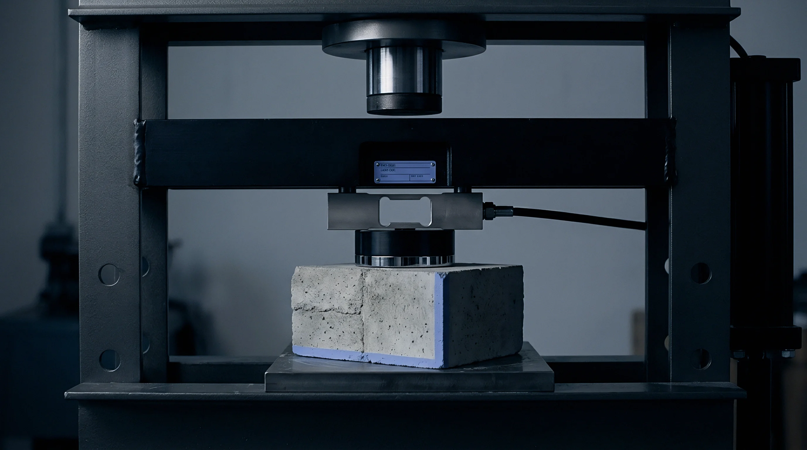
Drift
Thermal accumulation alters the physical geometry of low-conductivity tooling nests over successive operating hours. Steel pockets conduct heat away from cavity surfaces at 35 watts per meter-kelvin, while polymer tooling inserts retain heat with conductivities below 0.35 watts per meter-kelvin. Core temperatures within the polymer blocks climb from 25 degrees Celsius to 95 degrees Celsius over thirty molding cycles.
Glass transition temperatures for typical photopolymer resins range between 110 and 140 degrees Celsius. As bulk insert temperatures approach this thermal window, the storage modulus decreases nonlinearly, reducing structural stiffness under clamp loading.
Thermal Expansion Differential across Nests
Pocket dimensions change unevenly due to wide differences in thermal expansion coefficients. Tool steel expands at approximately 12 microstrain per kelvin, whereas polymer tooling resins expand at 35 to 55 microstrain per kelvin. A polymer nest measuring 150 millimeters across will expand outward by 0.38 millimeters when heated across an 80-kelvin delta.
Constrained inside a rigid steel pocket, this volumetric expansion converts directly into compressive internal pre-stress. The polymer insert bulges vertically upward across the parting plane by 0.04 to 0.07 millimeters, increasing localized kissing contact loads during mold closure.
Uncooled polymer tooling blocks experience continuous core temperature accumulation during short cycle intervals.
Structural grout plates beneath industrial turbines settle gradually under cyclic foundation loads in marine installations, matching the micro-creep relaxation patterns observed in resin tooling blocks compressed against steel pockets over hundreds of press strokes. Both structural systems undergo irreversible aggregate realignment under steady mechanical vibration and thermal cycling. The polymer inserts experience viscoelastic creep, shedding internal stress through permanent molecular rearrangement.
A constant clamping tonnage produces deeper cavity indentation with each successive shot, altering part wall thickness and distorting precision shut-off geometries.
Modulus Degradation Calculation and Force Compensation
Quantifying compressive deformation across extended cycle counts reveals the necessity of dynamic clamping control. Stated assumptions for this calculation: a two-cavity mold base carries SLA-printed ceramic-filled resin inserts (initial compressive modulus of 6,200 megapascals at 23 degrees Celsius) seated in a P20 steel chase; the projected cavity area per insert equals 45 square centimeters; the molding resin is polypropylene injected at a melt temperature of 210 degrees Celsius; mold cooling relies solely on external air blowers and base conduction.
Material testing published by resin formulators establishes the compressive yield strength of ceramic-filled stereolithography materials at 42 megapascals at 80 degrees Celsius under a 50-specimen test batch conducted under ASTM D695 guidelines. Lowering the ambient testing speed or shifting the filler matrix concentration moves this yield boundary by 15 percent. At shot 1, the insert operates at 25 degrees Celsius, exhibiting an elastic modulus of 6,200 megapascals.
Under a static closing force of 300 kilonewtons distributed over a total contact area of 90 square centimeters, the applied compressive stress equals 33.3 megapascals. The instantaneous elastic strain equals 0.00537, causing an axial deflection of 0.161 millimeters across a 30-millimeter-thick insert.
By shot 60, the internal insert temperature reaches 85 degrees Celsius. Modulus testing demonstrates a reduced stiffness of 2,800 megapascals at this temperature. If the press maintains the static 300-kilonewton clamp load, compressive strain jumps to 0.0119.
Total axial deflection reaches 0.357 millimeters. The parting land crushes by an additional 0.196 millimeters into the steel pocket. This crushing causes permanent plastic deformation across delicate features.
Dynamic clamp control counters this phenomenon by monitoring pocket load washers and cavity thermal sensors. The controller commands a reduced initial clamp tonnage of 90 kilonewtons during mold close, maintaining contact stress below 10 megapascals. As injection begins, the controller raises clamping tonnage to 260 kilonewtons precisely for the 0.8-second duration of peak injection pressure (55 megapascals melt pressure).
Immediately upon velocity-to-pressure switchover, the controller drops clamp tonnage to 120 kilonewtons for the 4.0-second packing phase, and down to 40 kilonewtons during the 25-second cooling interval. Dynamic regulation restricts total strain to 0.0035, preserving the integrity of the insert across 300 production cycles.
Thermal contact resistance values between the unpolished resin nest base and the ground tool-steel pocket boundary range between 350 and 600 watts per square meter-kelvin in published literature, yet actual heat conduction fluctuates wildly depending on grease film thickness and surface micro-roughness. Operational buyers protect their process windows by mounting auxiliary chilled copper heat spreaders directly beneath the polymer blocks rather than relying on unverified pocket conduction rates.
What remains unresolved is the precise cycle threshold where cumulative micro-cracking within the resin filler matrix accelerates macroscopic thermal fatigue regardless of dynamic force modulation.

Parting
Controlled platen separation balances internal melt expansion against external mechanical restraint. In conventional metal molds, clamp tonnage remains rigidly high to eliminate mold parting separation entirely. Polymer tooling nests require micro-breathing to vent trapped air without inducing mechanical crushing along fragile land perimeters.
If clamping force completely seals the parting plane before venting completes, trapped air burns the molded resin and scorches cavity edges. If the mold splits beyond critical clearance boundaries, molten polymer enters the gap, creating unacceptable flash defects.
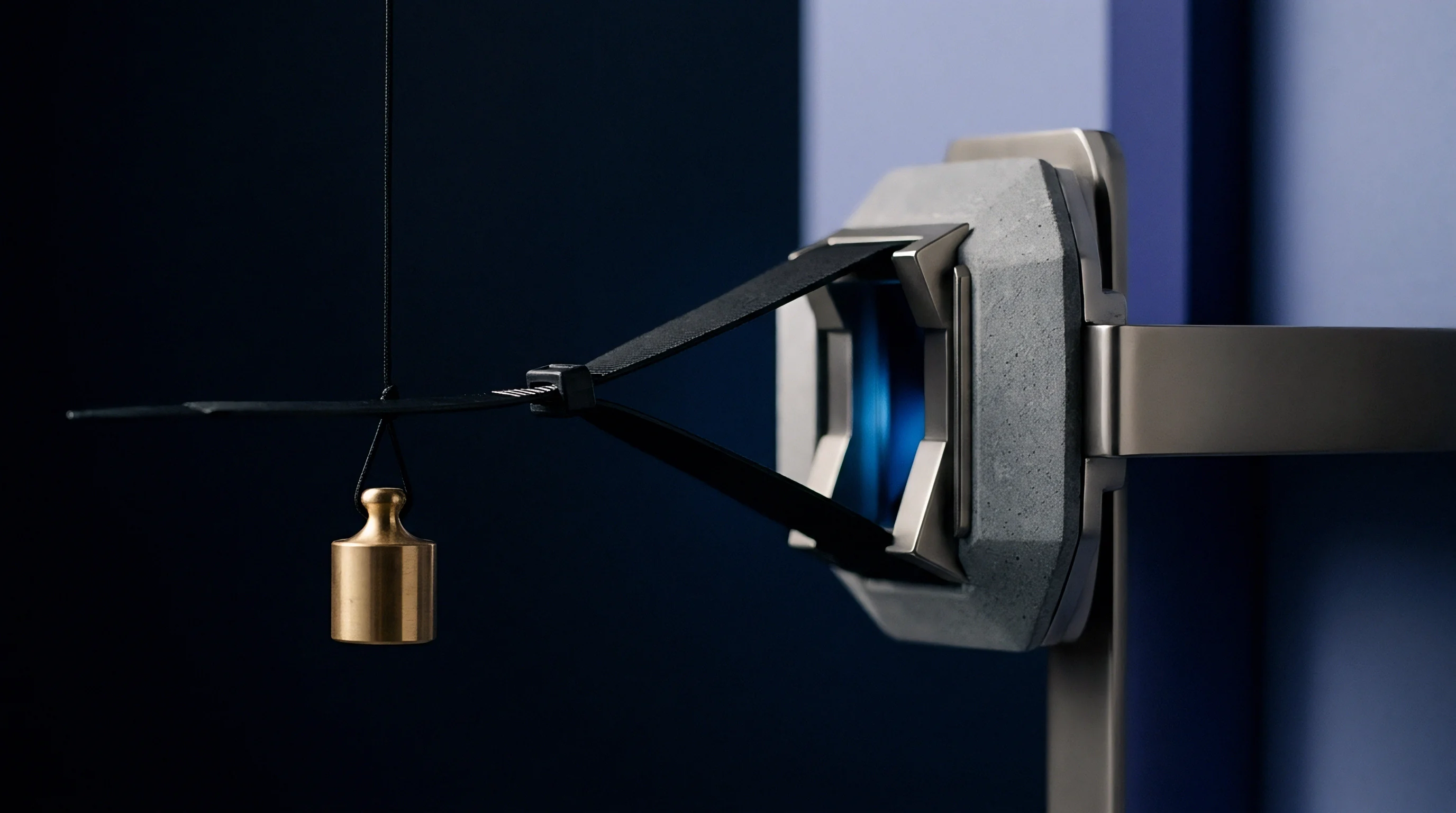
Breathing Control versus Flash Formation
Flash formation depends directly on melt viscosity, shear rate, and gap clearance at the parting interface. For standard injection-grade polymers, flash begins when parting separation exceeds specific clearance gates. Standard polypropylene flashe when gaps exceed 0.015 millimeters.
Polycarbonate flashes at 0.030 millimeters, while unfilled polyamide 66 enters gaps wider than 0.010 millimeters. Tooling nests must breathe between 0.008 and 0.012 millimeters under peak cavity pressurization to evacuate air while retaining the polymer melt.
Modulating clamp tonnage achieves micro-breathing dynamically. The clamp unit holds kissing pressure during the initial 90 percent of cavity filling, allowing the cavity parting line to separate by 0.010 millimeters under the hydraulic pressure of the incoming melt front. As the cavity pressure sensors detect the final fill transition, clamp tonnage scales upward rapidly to arrest mold opening before gap clearance reaches flash thresholds.
| Cycle Phase | Duration Band | Target Clamping Force | Insert Deflection Limit | Vent Clearance |
|---|---|---|---|---|
| Mold Close / Kiss | 0.5 to 1.2 s | 15% to 25% Machine Max | < 0.02 mm | 0.015 to 0.025 mm |
| Melt Flow / Injection | 0.6 to 2.5 s | 60% to 85% Machine Max | < 0.08 mm | 0.008 to 0.012 mm |
| Holding / Packing | 2.0 to 6.0 s | 35% to 50% Machine Max | < 0.04 mm | < 0.005 mm |
| In-Mold Cooling | 15.0 to 45.0 s | 10% to 20% Machine Max | < 0.01 mm | Closed |
| Decompression / Open | 0.3 to 0.8 s | 0% (Platen Release) | 0.00 mm (Free State) | Open |
| Values calibrate against standard 50-tonne to 150-tonne molding machines running 4-cavity polymer insert assemblies. | ||||
Insert Structural Degradation Patterns
Failure modes in polymer insert tooling correlate with inappropriate clamp tonnage profiling across specific operating cycles. Inspection logs from pilot tooling runs categorize structural damage across four primary manifestations:
- Parting Land Crushing occurs when excessive closing tonnage flattens micro-textured sealing perimeters, creating non-uniform witness lines across molded parts.
- Gate Erosion Pitting develops when high clamping forces distort runner alignment shims, generating localized frictional turbulence during rapid material injection.
- Pocket Floor Sinking results from continuous compressive cycling exceeding the matrix fatigue endurance limit, causing global downward drift of core heights.
- Core Deflection Bending takes place when unbalanced clamp pressure tips high-aspect cores laterally, causing asymmetric part wall thicknesses.
DIN ISO 20457 specifies an allowable parting line breathing tolerance of 0.012 millimeters for technical injection moldings before dimensional non-conformance occurs.
Verifying tool readiness requires comprehensive documentary evidence before mounting resin tooling into production presses. Engineering teams must compile technical packages containing verified physical property dossiers for tooling polymers, finite element deflection simulations under staged clamping loads, sensor calibration certificates for pocket load washers, and recorded hydraulic valve response latency logs.
Under standard commercial tooling supply agreements based on VDI 3405 guidelines, supplier warranty coverage for insert longevity terminates immediately if machine data records show parting line clamp loads exceeded 45 megapascals of contact stress during any point of the operating cycle.
Margin
Economic boundaries in polymer insert tooling depend directly on throughput speed and total usable shot life. Additive tooling nests offer rapid turnaround, delivering pilot quantities within three to five days of CAD freeze. Steel tooling demands eight to twelve weeks of machining lead time.
The trade-off centers on cycle times and durability. Polymer inserts require prolonged cooling times due to low thermal conductivity, stretching cycle durations to 45 or 90 seconds compared to 15 seconds for production steel molds. Dynamic clamping control preserves inserts for 200 to 1,000 shots, shifting the breakeven economics of bridge tooling.
Capital equipment commitments hinge on real-time control capabilities. Upgrading an existing hydraulic press with fast-response servo valves, pocket quartz transducers, and digital feedback integration requires an expenditure of 25,000 to 45,000 dollars per machine. Operators running high-mix low-volume production recoup this investment by extending average polymer insert operational lifespan from 40 shots to 450 shots.
Tool fabrication costs for 3D-printed ceramic-filled inserts run between 800 and 2,500 dollars per set. Premature insert failure destroys project margins through press downtime and frequent reprinting.
Production scheduling dictates tooling material selection. When total demand remains below 500 units, dynamic clamp management on printed polymer nests yields significant landed cost advantages over machined aluminum tooling. Aluminum molds require tooling investments of 12,000 to 25,000 dollars, which cannot amortize effectively over small batch volumes.
Above 1,500 units, the cooling cycle penalty of polymer inserts shifts financial metrics toward hardened metal tooling.
Low-conductivity tooling nests achieve commercial viability only when clamp force profiles adapt to the shifting mechanical properties of the polymer matrix.
Scaling volume prematurely without qualified tonnage control destroys tooling investments through catastrophic insert deformation. Operations directors evaluate machine data files before authorising continuous multi-shift production on soft nests. Every injection cycle must balance containment against tool preservation.
Clamping forces must never exceed the load required to contain the melt front during peak injection.