Designing Factory Electrical Busbars and Compressed Air Loops
Factory utilities succeed when busbar thermal ratings and pneumatic ring volumes absorb peak coincident cyclic surges without central supply throttling.
Load
A stamping press clutch drops out at 5.2 bar gauge while the main distribution board registers 640 amperes on an 800-ampere breaker. Downstream pneumatic actuators hesitate, causing transfer arms to miss the indexing notch on an automotive stamping sub-line. At the primary feeder, copper conductors radiate heat through the enclosure at 78 degrees Celsius under an ambient plant floor reading of 24 degrees Celsius.
The nameplate ratings on the machinery indicate substantial design margin, yet simultaneous operation triggers localized undervoltage faults and pneumatic pressure troughs. Plant engineering teams often respond by turning up compressor discharge setpoints or swapping breakers for higher trip thresholds. That reaction addresses symptoms while multiplying electricity consumption and degrading capital assets.
Determining real operating draw requires separating nominal nameplate capacity from coincidental demand. Production machines rarely pull full rated current or maximum pneumatic volume simultaneously across an entire manufacturing shift. Nameplate values aggregate the maximum theoretical consumption of every onboard motor, heating element, servo drive, and pneumatic cylinder.
Operating profiles follow cyclical patterns where peak draws endure for seconds during acceleration, clamping, or rapid traverses, followed by lower holding or idle draws. Summing connected loads produces heavily oversized infrastructure that runs at poor electrical power factors and keeps central air compressors running in inefficient unloaded cycles. Sizing utilities strictly for average demand starves equipment during unavoidable production overlaps.
A 2000-ampere busway trunk operating at 40 degrees Celsius ambient loses three percent of its current-carrying capacity for every five degrees Celsius rise above that rating point.
Design teams calculate diversity factors by dividing peak coincident draw by the total connected load across a designated production bay. In high-volume consumer goods assembly, where dozens of identical pneumatic pick-and-place actuators cycle asynchronously, diversity factors settle between 0.45 and 0.60. In heavy machining and stamping facilities, diversity behaves erratically.
When four 150-tonne presses strike sheets within the same 200-millisecond window, instantaneous demand spikes toward 0.85 of connected nameplate capacity. Electrical switchgear and compressed air distribution must absorb these transient coincidences without letting line voltage drop past five percent or air pressure decay past 0.3 bar at the furthest machine terminal.
Peak Coincidence in Automotive and Stamping Cells
Press lines and robotic weld stations impose aggressive cyclical shock profiles on factory distribution systems. Resistance spot welders fire for several electrical cycles, drawing brief bursts of single-phase current that unbalance three-phase feeder networks. Concurrently, pneumatic counterbalance cylinders, sheet feeders, and pneumatic ejectors demand high volumes of compressed air within milliseconds of die opening.
Calculating aggregate demand in these environments cannot rely on annual energy tallies or utility billing meters that average consumption over 15-minute integration windows. Those 15-minute averages hide sub-second voltage dips that reset sensitive programmable logic controllers and obscure pneumatic pressure drops that trigger safety interlocks.
Transient electrical spikes generate mechanical stress along busbar supports through electromagnetic fault forces. When adjacent busbars carry momentary surge currents approaching ten times continuous rating, the magnetic fields induce physical repulsion forces proportional to the square of the peak amperage. Inadequate bracing permits conductor deflection, fatiguing the insulating supports and loosening bolted joint connections over time.
In compressed air networks, identical rapid cycling creates acoustic pressure waves that reflect back through distribution pipework, causing local pressure fluctuations that confuse point-of-use regulators. Stabilizing these utility grids requires mapping the temporal overlap of each primary consumer on the line.

Empirical Diversity Ratios across Production Shifts
Field measurements collected across multi-shift facilities demonstrate that utility demand shifts fundamentally between initial line ramp-up, steady-state production, and tooling changeovers. Plant start-up introduces synchronized motor inrush currents and simultaneous line pressurization that challenge distribution limits. Once steady state begins, random cycle displacement naturally smooths coincident demand.
Tooling changeovers drop primary demand while leaving ancillary equipment, such as cabinet coolers, desiccant dryer purges, and hydraulic auxiliary pumps, running continuously at poor efficiency.
- Intermittent motor inrush creates localized line voltage sag when large hydraulic power packs start against loaded manifolds, dropping control circuit voltages below tolerance limits.
- Unsynchronized actuator firing produces rapid cyclic pressure decay in pneumatic headers lacking localized receiver storage capacity.
- Single phase load stacking unbalances neutral busbars, driving excessive current through neutral conductors and elevating temperatures inside busway housings.
- Air drying purge cycles draw continuous utility volume during planned production breaks, consuming high compressor power when production lines stand idle.
The assumed 0.65 to 0.75 diversity coefficient cited in general plant engineering literature remains difficult to defend across automated assembly facilities. Field logging demonstrates that momentary production resynchronization during cell pauses swings the measured peak demand by 40 percent above calculated averages. To manage that uncertainty, engineering teams deploy high-speed electrical loggers and digital pressure transducers at sub-headers for 14 continuous operating days to capture real 100-millisecond spikes before finalizing trunk dimensions.
Sizing conductors and piping without this continuous transient baseline creates chronic machine starvation during volume growth.
Calculating utility sizing from average consumption produces infrastructure that fails whenever machine cycles accidentally align.
Busway
Sandwich-style electrical busway systems distribute large current volumes across industrial floorplates with greater spatial flexibility than bundled cable trays. In a sandwich construction, insulated aluminum or copper busbars are pressed together within an extruded aluminum or sheet steel housing without internal air gaps. This intimate physical contact promotes conduction cooling through the outer casing, minimizing the cross-sectional metal area required for a given ampere rating.
Eliminating air space between conductors also reduces inductive reactance, which directly curtails cumulative voltage drop across lengthy distribution runs.
Selecting busway over traditional cable and conduit alters the maintenance and operational profile of the building. Traditional cable pulls require dedicated pull boxes, high bend radiuses, and extensive labor hours during initial installation. Once pulled, copper cables inside conduit provide continuous, joint-free runs back to the sub-station board.
Busway systems rely on modular segments bolted together at three-metre or five-metre intervals. Every joint introduces a mechanical interface subject to torque relaxation, thermal expansion fatigue, and environmental corrosion. Designing a durable busway system centers on managing joint integrity, fault withstand ratings, and continuous thermal rise under non-linear loads.
Conductor Metallurgy and Sandwich Housing Dynamics
Aluminum busbars offer a favorable strength-to-weight ratio and lower raw material procurement costs compared to electrolytic tough pitch copper. Copper provides higher electrical conductivity, lower thermal expansion rates, and superior resistance to galvanic oxidation at bolted connections. An aluminum conductor must feature a cross-sectional area approximately 60 percent larger than a copper bar to achieve an equivalent continuous ampacity rating.
The larger exterior surface area of aluminum busway housings improves convective heat transfer to surrounding air, partially offsetting the metal’s lower native conductivity.
Differential thermal expansion between conductors and joint hardware creates mechanical strain during cyclic factory shifts. Copper expands at approximately 17 micrometres per metre per kelvin, whereas aluminum expands at 23 micrometres per metre per kelvin. Over a 100-metre run experiencing a 40-kelvin operational temperature swing, an aluminum busway expands by 92 millimetres compared to 68 millimetres for copper.
Without dedicated internal expansion joints, this movement shears mounting brackets and distorts the silver-plated joint contact faces. Extruded aluminum housings serve as an integral equipment grounding conductor, providing an extremely low-impedance ground return path that rapidly clears ground faults compared to internal steel ground straps.
| Performance Parameter | Copper Sandwich Busway | Aluminum Sandwich Busway | Copper Cable in Ladder Tray |
|---|---|---|---|
| Installed Weight per Metre (kg/m) | 32.5 | 21.0 | 48.2 |
| Voltage Drop per 100m at Full Load (V) | 4.1 | 4.6 | 7.8 |
| Reactance at 50Hz (milliohms/m) | 0.015 | 0.018 | 0.045 |
| Operating Temperature Rise at Rated Load (K) | 48 | 52 | 42 |
| Short Circuit Withstand Capacity 1s (kA RMS) | 80 | 65 | 50 |
Fault Level Withstand and Voltage Regulation
Short-circuit currents subject busbars to extreme thermal and electrodynamic forces before protective switchgear can clear the fault. During a bolted three-phase fault, initial asymmetrical peak currents produce violent repulsive forces between adjacent phase bars. Busway housings must restrain the bars from bowing and shorting phase-to-phase or phase-to-ground.
Standard IEC 61439-6 establishes the structural verification protocols for low-voltage busbar trunking systems, defining short-time withstand current ratings for durations of 0.1 to 1.0 second alongside peak withstand ratings.
Calculating voltage regulation across long factory runs requires analyzing the resistive and reactive parameters of the busway under varying load power factors. When supplying induction motors operating at 0.80 lagging power factor, the line inductive reactance contributes substantially to voltage drop. In contrast, when supplying switch-mode power supplies and variable frequency drives with high displacement power factors, conductor resistance governs the loss.
The design limit for interior distribution feeders is typically three percent maximum voltage drop from the main distribution transformer to the final plug-in tap-off box, reserving an additional two percent drop for machine drops.
Standard IEC 61439-6 clause 10.10 limits permissible temperature rise across busway terminal connections to 70 Kelvin above ambient operating conditions.
Operating conditions directly modify these thermal boundaries. The 55-kelvin temperature rise rating commonly specified in procurement dossiers rests on type-test laboratory certifications conducted on three-metre sample sections horizontally mounted in still air at 35 degrees Celsius. When busways run horizontally through factory roof spaces where warm air pools at 48 degrees Celsius, conductor ampacity must be derated by 12 percent.
Operating non-linear loads with high third-harmonic content drives unexpected currents through the neutral conductor, requiring a 200-percent oversized neutral bar to prevent catastrophic overheating inside enclosed sandwich geometries.

Joint Integrity and Thermal Drift Verification
Modular busway segments join together using double-headed torque-indicating bolts that snap off at a predetermined clamping force, typically between 50 and 70 newton-metres. Belleville washers maintain constant clamping pressure across the joint stack as the conductors expand and contract thermally. Over-torquing crushes the copper or aluminum plating, accelerating local oxidation; under-torquing leaves microscopic air gaps that elevate contact resistance.
A micro-ohmmeter test across every completed joint verifies connection health, with acceptable joint resistances remaining within 1.2 times the equivalent resistance of an unbroken conductor section of identical length.
- Visual joint inspection confirms Belleville washers sit correctly convex and torque break-away heads sheared cleanly during mechanical assembly.
- Micro-ohmmeter resistance logging measures contact resistance across each phase bridge to isolate high-resistance junctions before energization.
- Insulation resistance verification tests phase-to-phase and phase-to-ground isolation using a 1000-volt direct current megohmmeter for 60 seconds.
- Baseline thermographic scanning captures thermal signatures across all bolted joints under minimum 50 percent continuous operational load.
IEC 61439-6 clause 10.11 enforces rigorous short-circuit tests that disqualify uncertified field modifications, meaning that drilling busway housings to route cables voids the assembly rating and invalidates factory insurance policies.

Header
Compressed air distribution systems in manufacturing facilities suffer from a thermodynamic reality: approximately 85 to 90 percent of electrical energy supplied to an air compressor transforms directly into heat, leaving only 10 to 15 percent converted into pneumatic work potential. Compressed air represents the most expensive industrial utility on the factory floor. Generating one normal cubic metre per minute of compressed air at 7.0 bar gauge consumes approximately 6.5 to 7.5 kilowatts of electrical power.
Miscalculating distribution pipework compounds these operating losses through excessive frictional resistance, localized turbulence, and artificial demand driven by elevated supply pressures.
Piping layout design determines the pressure stability delivered to automated machinery. Dead-end branch configurations cause pressure to fall progressively toward the end of the line, forcing utility operators to elevate compressor discharge setpoints to satisfy the furthest machine tool. Elevating central system pressure from 6.0 bar gauge to 7.5 bar gauge increases compressor power draw by approximately ten percent and increases system air loss through unmetered leaks by 15 percent.
A closed-loop ring main header eliminates dead ends by feeding air to any consumption point from two parallel directions, effectively halving airflow velocity through the pipe and cutting frictional pressure drop by up to 75 percent.

Ring Main Geometries and Fluid Friction
Connecting supply piping into a continuous loop equalizes flow dynamics across the manufacturing perimeter. When a machine cycles downstream, air flows toward the demand point through both branches of the ring, dampening velocity spikes and reducing dynamic turbulence. Sizing the primary header requires calculating fluid friction using the Darcy-Weisbach equation combined with the Colebrook-White formulation for turbulent pipe flow.
Internal surface roughness dictates the friction factor: smooth extruded aluminum and stainless steel pipework exhibit absolute roughness values between 0.0015 and 0.005 millimetres, whereas unlined carbon steel pipe exhibits roughness values between 0.045 and 0.10 millimetres, increasing with age as internal moisture induces oxidation.
The total equivalent length of the distribution network accounts for localized friction introduced by mechanical fittings, isolation valves, and direction changes. A standard 90-degree threaded elbow in a 100-millimetre diameter line adds equivalent frictional resistance equal to 3.2 metres of straight pipe; a full-port ball valve adds only 0.6 metres. Designing headers with long-radius bends and swept-tee connections minimizes pressure degradation.
Target sizing limits total header pressure drop from the compressor room receiver to the furthest distribution sub-header to a maximum of 0.1 bar under peak instantaneous factory demand.
| Header Nominal Bore (mm) | Max Airflow at 6 m/s (Nm³/min) | Max Airflow at 10 m/s (Nm³/min) | Friction Drop per 100m Extruded AL (bar) | Friction Drop per 100m Carbon Steel (bar) |
|---|---|---|---|---|
| 50 | 5.8 | 9.7 | 0.082 | 0.145 |
| 80 | 14.8 | 24.7 | 0.031 | 0.058 |
| 100 | 23.2 | 38.6 | 0.016 | 0.030 |
| 150 | 52.1 | 86.8 | 0.005 | 0.010 |
| 200 | 92.6 | 154.3 | 0.002 | 0.004 |
What Dictates Header Storage Volume during Cyclic Tool Spikes?
Pneumatic machinery operating on short, aggressive cycles draws air faster than central compressors can ramp their output. Rotary screw compressors require several seconds to transition from unloaded idle to fully loaded delivery, and variable-speed units require time to accelerate drive motors. During this mechanical response lag, air must come from stored pneumatic volume within the distribution system.
If that volume proves insufficient, system pressure plummets locally, causing machine faults. While traditional designs install large wet and dry receiver tanks inside the compressor room, distributed secondary storage tanks placed adjacent to high-draw production cells provide far superior transient protection.
The internal volume of the primary ring main header itself acts as a distributed secondary air receiver. Sizing an oversized header creates valuable capacitance directly above the production floor. Calculating the required physical receiver volume involves multiplying the peak deficit volumetric flow rate by the maximum duration of the demand surge, divided by the allowable pressure drop across that interval.
For an automated stamping cell pulling an instantaneous deficit of 12 normal cubic metres per minute for 15 seconds with an allowable pressure decay of 0.4 bar, the calculation dictates a local storage volume of at least 7.5 cubic metres, split between dedicated local receivers and the interior volume of the primary header pipe.
Oversizing primary distribution pipework converts passive conduit into functional storage capacity that shields tools from supply transients.
High-pressure gas manifold systems in deep-sea diving and aerospace propellant test complexes apply this exact acoustic damping principle to eliminate rapid valve oscillation. In an industrial plant, smooth header capacitance isolates variable mechanical loads from the central compressors, stabilizing operation. The published 0.1 bar allowable pressure drop target rests on steady-state fluid mechanics calculations for smooth-bore extruded pipe at 7.0 bar gauge.
In aging installations where internal scale, residual oil varnish, and piping sediment triple the pipe wall roughness, dynamic pressure loss spikes sharply above calculated values. Facility planners who ignore internal pipe deterioration find their machines cycling out on low-pressure faults within two years of commissioning.

Loop Velocity Limits and Droplet Separation
Air velocity within primary distribution headers must remain strictly controlled to avoid entraining liquid water and compressor lubricants. Air leaving compressor aftercoolers and refrigerated dryers carries residual moisture and microscopic condensate droplets. If air velocity inside the main header exceeds 6 to 8 metres per second, the gas stream holds moisture droplets in suspension, carrying water directly into sub-distribution drops and machine valving.
Maintaining primary header velocities below 6 metres per second promotes gravitational drop-out of condensation, allowing water to collect in low-point drip legs equipped with zero-loss automatic condensate drains.
Distribution headers must slope gently away from the compressor house at a gradient of 1:100 toward dedicated drainage points. Installing level pipework allows condensation to pool in low sections, reducing the effective internal diameter of the line and creating slugs of water that travel down the pipe during sudden flow surges. Sizing branch take-offs and drop lines requires slightly higher permissible velocities, typically between 10 and 15 metres per second, because drop lines feature short physical lengths where cumulative frictional loss remains minor.
Under-sizing a distribution loop starves high-speed production tools, prompting operators to raise compressor discharge pressures and permanently inflate the plant energy bill.
Tap
Interfacing main utility trunks with floor-mounted machines requires rigorous termination standards. A well-designed overhead busway or pneumatic ring main fails operationally if the vertical drops connecting to individual manufacturing cells introduce flow restrictions, physical strain, or electrical trip vulnerabilities. The drop line represents the boundary between facility infrastructure and dynamic production equipment.
Machine vibration, thermal cycling, and layout adjustments concentrate mechanical stress at these connection points.
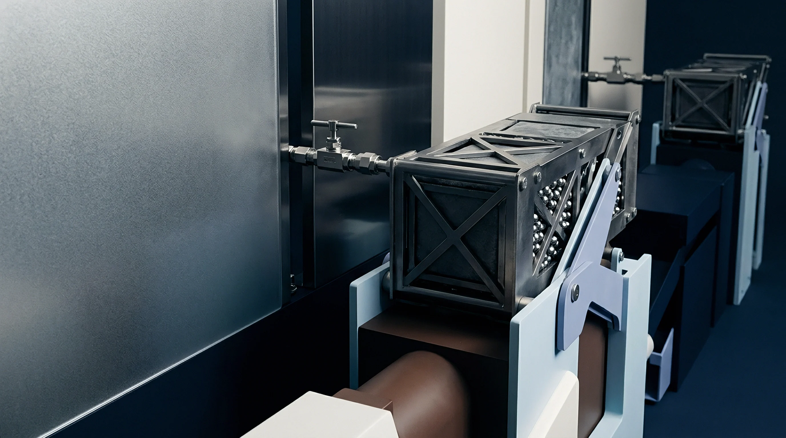
Overhead busbar systems facilitate equipment drops through plug-in tap-off boxes installed along the busway casing. These tap-off units clamp directly onto the internal conductor bars through purpose-built opening ports equipped with automatic safety shutters. In parallel, pneumatic take-offs connect to the overhead ring main to feed point-of-use service units comprising filtration, pressure regulation, and lubrication assemblies.
Isolating both utilities from physical line interference preserves operational uptime.

Point of Use Conditioning and Droplet Elimination
Pneumatic drop lines must tap into the top of the main overhead distribution header through swan-neck or gooseneck bends. Fabricating a take-off that exits from the side or bottom of a header pipe directs entrained moisture, scale, and compressor lubricant directly into sensitive machine valving. By looping the take-off pipe upward out of the top of the header before descending toward the floor, the connection prevents pooled condensate from entering the drop line.
Condensate remains in the bottom of the sloped primary header until it reaches an automated drainage station.
At the base of the vertical drop, air enters a three-stage filter-regulator-lubricator unit matched to the equipment’s clean air requirements. ISO 8573-1 defines compressed air purity classes across particle size, water pressure dew point, and oil content. Precision electronic assembly and laser cutting require Class 1.2.1 air, demanding point-of-use sub-micron coalescing filtration and desiccant drying.
Heavy mechanical fabrication operates reliably on Class 4.4.4 air. Sizing point-of-use regulators requires verifying their internal flow coefficient: an undersized regulator creates substantial dynamic pressure loss during cylinder actuation, even when upstream header pressure reads perfectly on static gauges.
| Drop Line Diameter (mm) | Peak Flow Capacity (Nm³/min) | Swan-Neck Dynamic Drop (bar) | Electrical Plug-in Tap Ampacity (A) | Cable Size to Cell Panel (mm²) |
|---|---|---|---|---|
| 15 | 0.8 | 0.38 | 32 | 6 |
| 25 | 2.5 | 0.18 | 63 | 16 |
| 32 | 4.6 | 0.10 | 125 | 35 |
| 50 | 11.2 | 0.04 | 250 | 95 |
| 80 | 28.5 | 0.02 | 400 | 185 |
Do Plug-In Tap off Boxes Introduce Cascading Breaker Trips?
Electrical tap-off boxes install directly onto live or de-energized busway tracks to supply individual machine panels through localized circuit protection. When a short circuit occurs inside a machine control cabinet, protective devices must isolate that specific fault without tripping the upstream busway feeder breaker. Achieving total overcurrent selectivity requires coordinating the time-current tripping curves between the branch circuit breaker inside the tap-off box and the primary air circuit breaker feeding the entire busway run.
Molded case circuit breakers inside compact tap-off boxes possess limited short-circuit breaking capacity compared to the high prospective fault currents available along major busway runs. If the short-circuit rating of a tap-off box breaker sits at 25 kiloamperes while the busbar fault level at that location reaches 40 kiloamperes, a direct fault will cause the tap-off breaker to fail violently. Designers implement current-limiting breakers or backup fuse protection inside tap-off units to clear high-energy faults within the first half-cycle.
Cascading trip failures occur when upstream electronic trip units lack sufficient short-time delay separation, causing an entire manufacturing bay to black out due to a single servo drive short.
Mechanical Anchoring and Flexible Whip Isolations
Vibration generated by high-speed stamping presses, industrial robots, and rotating CNC spindles transmits into utility drop lines if machines attach rigidly to overhead infrastructure. Rigid conduit and steel piping bolted directly between a vibrating machine frame and an overhead busway or air header cause joint loosening, fatigue cracking, and structural failure over time. Engineering specifications demand flexible mechanical isolation at the base of every drop line.
- Flexible pneumatic hose whips absorb multi-axis machine vibration while preventing dynamic cyclic loads from fatiguing overhead piping joints.
- Liquid-tight flexible conduit runs isolate machine cabinet movements from overhead busway drop boxes, preventing mechanical pull-out on terminal lugs.
- Dedicated vertical drop supports anchor piping and bus-drop cables to structural building columns rather than suspending loads directly from the busway casing.
- Quick-disconnect lockable ball valves allow immediate physical isolation of compressed air at floor level during emergency maintenance interventions.
Installers often claim that small machines generate negligible vibration and can connect directly with rigid pipework to save installation hours. Field audits reveal that rigid connections inevitably crack at threaded joints and induce micro-fretting corrosion on busway tap-off contacts.
Penalty
Operating poorly matched electrical busways and compressed air networks extracts an ongoing commercial toll through wasted energy, unpredicted maintenance interventions, and restricted plant expansion capability. Compressed air leakage represents a direct operational drain that grows continuously if left unmanaged. In an unmonitored plant, air leaks consume 20 to 30 percent of total compressor output.
A single three-millimetre leak orifice in a 7.0 bar gauge compressed air network discharges approximately 0.73 normal cubic metres per minute, wasting roughly 5.0 kilowatts of electrical compressor power. Operating continuously across an 8000-hour production year, that single leak wastes 40,000 kilowatt-hours of electrical energy.
When distribution systems choke utility delivery, plant operators instinctively overcompensate by adding central capacity. Plants procure additional 150-kilowatt air compressors or install secondary distribution transformers because production cells complain of low pressure or thermal circuit breaker tripping. The true bottleneck resides in the distribution network: inadequate header storage volume, undersized vertical drops, or elevated thermal resistance across unverified busway joints.
Adding upstream supply equipment without resolving distribution friction accelerates capital expenditure while failing to stabilize point-of-use delivery.
Unloaded Power Losses in Central Compressors
Fixed-speed rotary screw compressors control line pressure through load-unload cycles. When system pressure reaches its upper setpoint, the compressor closes its inlet valve, running in an unloaded state while the drive motor continues spinning. An unloaded compressor burns approximately 25 to 35 percent of its full-load electrical power while delivering zero useful compressed air to the factory floor.
If high header friction prevents pressure signals from reaching the compressor management controller smoothly, compressors short-cycle between load and unload modes, accumulating motor starts and burning excessive power.
Elevating plant operating pressure to overcome distribution pipe losses directly degrades compressor performance. Operating at higher discharge pressure increases the compression ratio, which accelerates heat generation, thins lubricating oils, and elevates moisture loading on downstream dryers. Refrigerated dryers consume greater electrical power to handle the increased heat load, while desiccant dryers consume up to 15 percent of their rated capacity in purge air simply to regenerate desiccant beds at elevated pressures.
In electrical busbars, running near continuous thermal limits accelerates insulation degradation, with every ten-degree Celsius rise in conductor operating temperature halving the functional lifespan of organic busbar insulation wraps.
Systematic acoustic logging reveals that undetected distribution leaks typically waste a quarter of all generated compressed air capacity.
Thermal Dissipation and Floor Reconfiguration Expense
Modern manufacturing floors require periodic layout reconfigurations to accommodate new model launches, process upgrades, and shifting volume allocations. The choice of utility distribution infrastructure dictates the financial and timeline penalties associated with these conversions. Traditional hard-wired conduit systems require decommissioning cables back to breaker panels, installing new cable trays, and executing complex electrical pulls.
These modifications force extended line shutdowns that cost tens of thousands of dollars per shift in lost production throughput.
Plug-in sandwich busways allow maintenance crews to install, remove, or reposition machine tap-off boxes in minutes without de-energizing the main trunk line, provided safe working procedures and arc-flash boundaries are maintained. Compressed air ring mains configured with modular aluminum piping and quick-connect clamp fittings permit rapid relocation of drop legs without pipe threading or hot-work welding permits. The initial capital procurement cost of modular aluminum busway and smooth-bore aluminum air piping sits 15 to 25 percent above carbon steel and cable-in-tray alternatives.
That initial premium is amortized across the first two major production floor reconfigurations through reduced contractor labor and compressed downtime windows.
Diagnostic Stage Gates Prior to Expansion
Before committing capital to physical plant expansions, engineering leadership executes a structured utility audit to expose latent distribution bottlenecks. The Diligence Examiner reviews 90 days of high-resolution electrical sub-meter data and pneumatic logging records. If existing compressors log more than 30 percent unloaded runtime while line pressure decays below tolerance during shift start-up, adding machines will cause immediate cascading trips.
Expansion requires formal qualification of utility delivery at the point of use.
Baseline commissioning records establish the operating envelope against which future machine additions are measured. Ultrasonic acoustic leak surveys, calibrated micro-ohmmeter joint logs, and infrared thermal scans constitute the definitive evidence dossier of system health. Neglecting these baseline audits leaves operating management exposed to chronic operational drift, where utility lines quietly degrade until a single added machine triggers line-wide failures.
How far can modular utility topologies be extended across high-speed robotic cells before dynamic harmonics and pressure wave resonance force the abandonment of decentralized distribution entirely?