Decoupling Dynamic Thermal Expansion Gradients from Multi-Axis Metrological Errors in High-Speed Pilot Scale-Up
Decoupling thermal expansion from multi-axis metrological error requires synchronous edge sensor telemetry, structural state-space models, and axis compensation.


Spindle
High speeds inside precision tooling equipment convert rotational friction directly into thermal fluxes. Operating drives at rotational velocity rates exceeding fifteen thousand revolutions per minute generates continuous power losses across angular contact bearings, rotor windings, and mechanical shaft seals. These localized thermal loads migrate outward into surrounding housings, causing measurable physical growth along the rotational centerline long before the machine reaches thermal equilibrium.
Friction generates immediate surface distortion. In high-speed pilot lines, driving a shaft from rest to target velocity creates rapid localized temperature rises exceeding thirty degrees Celsius within twenty minutes of initial startup. The resulting structural elongation along the Z-axis displacement path creates uncompensated positioning offsets.
When pilot scale operations scale up throughput rates, these dimensional changes distort part features and invalidate baseline metrology reference points established under cold ambient conditions.

Rotational Heat Generation Mechanics
Motor windings and ceramic bearing packs act as localized thermal sources. Bearing preloads increase heat output. Power losses scale with the square of the rotational speed, transferring heat into the housing sleeves and structural casting interfaces.
Viscous shear losses inside lubricant slurries contribute further localized energy inputs, accelerating shaft elongation.
Coolant flow modifies structural boundaries. While internal jacket cooling removes bulk thermal energy from drive sleeves, temperature offsets persist across internal race clearances. The resulting dynamic temperature differentials produce non-uniform axial displacement along spindle housings, introducing severe geometric pitch and yaw errors at the tool point.

Non Linear Axis Growth Behavior
Temperature rises during initial startup follow exponential curves before reaching equilibrium. During this transient warm-up phase, shaft growth rates frequently reach two micrometers per minute. This growth rate shifts position readings off physical encoder baselines established during machine idle states.
- Viscous shearing in grease sumps increases internal housing temperatures by up to twelve degrees Celsius per hour of continuous high-speed execution, forcing baseline axis displacement.
- Motor coil thermal leakage penetrates drive mount housings, creating localized asymmetric expansion across key structural mounting flanges.
- Rotational preload expansion increases bearing contact stress, accelerating localized heat generation and compounding total z-axis tool tip positioning error.
- Transient fluid cooling drops introduce sharp thermal gradients along housing walls, inducing structural bending and angular tool tilt.
Equipment integrators frequently claim that machine structures reach full thermal stability within thirty minutes of spindle activity. Industrial line auditing shows that deep structural castings require up to four hours of continuous high-speed operation to reach steady-state thermal equilibrium.

Conduction
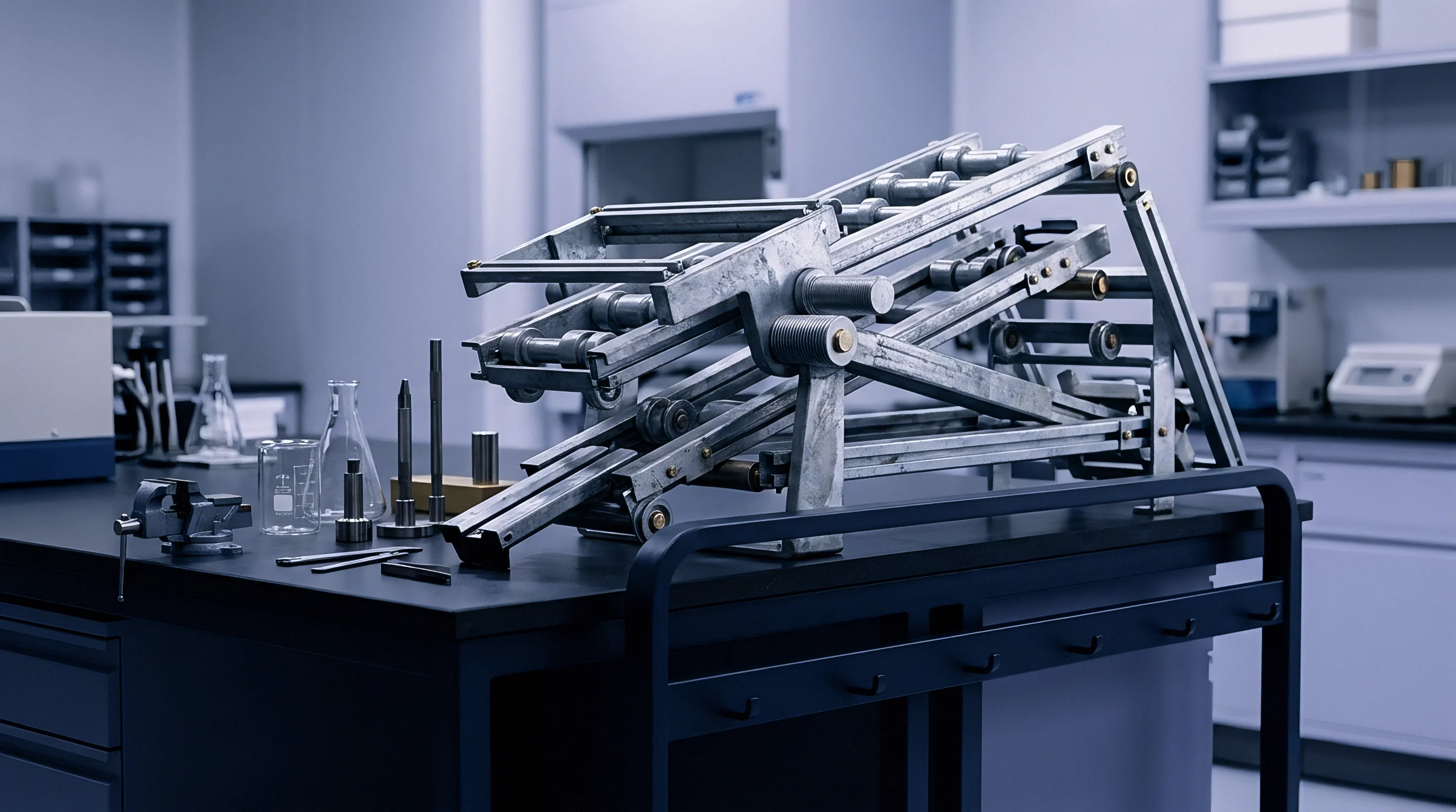
Energy flows through machine structural frames along multi-directional pathways. Conduction through mechanical interfaces transfers heat from drive housings into column castings, linear guide blocks, and machine bed assemblies. Cast iron dissipates energy slowly.
This slow dissipation forms steep internal thermal gradients that vary dynamically with spindle speed and axis acceleration duty cycles.
Spatial gradients alter structural geometry. When a machine casting experiences an internal temperature difference of just two degrees Celsius between its front and rear faces, asymmetric thermal expansion forces the column to bow outward. This structural bowing shifts the tool tip off its commanded path, translating a microscopic material expansion into substantial multi-axis positioning errors.

Structural Heat Sinks and Energy Paths
Machine beds receive kinetic dissipation from slide pack movements. Linear motor drive tracks deposit high localized energy loads into guidance axes during fast acceleration cycles, creating localized thermal pockets within structural bed castings. These dynamic heat sources alter structural dimensions dynamically during complex multi-axis toolpath execution.
| Material Class | Thermal Conductivity (W/m·K) | Thermal Expansion Coefficient (ppm/K) | Thermal Diffusivity (mm²/s) | Structural Stability Index |
|---|---|---|---|---|
| Gray Cast Iron (GG25) | 45.0 | 10.5 | 13.2 | Moderate |
| Ductile Cast Iron (GGG60) | 36.0 | 11.5 | 10.8 | Moderate |
| Polymer Concrete | 1.5 | 12.0 | 0.8 | High Damping |
| Invar 36 Alloy | 10.5 | 1.2 | 2.8 | Ultra High |
| Structural Steel (S355) | 50.0 | 12.0 | 14.5 | Low |

Transient Spatial Gradients across Castings
Uneven temperature distribution across large machine bases causes bow and torsion. As structural members absorb kinetic and friction energy, internal conductive heat flow creates complex three-dimensional temperature fields. Measuring temperatures at isolated surface locations fails to capture internal thermal gradients, leading to incorrect assumptions regarding structural distortion.
Cast iron machine bases require four hours under continuous high-speed duty cycles to reach thermal equilibrium, during which structural bending creates spatial positioning errors up to thirty-five micrometers.
Failure to map dynamic heat conduction pathways across machine structures leads to spatial positioning errors that ruin tight-tolerance manufacturing runs during scale-up, wasting material and consuming pilot production capacity.


Deflection
Multi-axis geometric distortion manifests as spatial positioning shifts. Thermal expansion gradients induce localized strain fields across linear guides and rotational joints, producing non-linear spatial errors across all six kinetic degrees of freedom per axis. These positional, straightness, pitch, yaw, roll, and squareness errors compound as machine axes traverse their full stroke during high-speed pilot runs.
Abbé offsets magnify angular positioning deviation. When dynamic expansion tilts a structural column, the spatial separation between the linear scale reading point and the actual tool contact point amplifies small angular pitch and yaw errors into significant positioning offsets at the workpiece surface.

Volumetric Kinematic Coupling Errors
Combined axis translations accumulate geometric deviations across three dimensions. Dynamic thermal strain changes the effective squareness between perpendicular guide rails. An angular squareness error of fifteen arcseconds induced by thermal gradient distortion produces over seventy micrometers of volumetric positioning deviation at the maximum stroke envelope.
| Error Component | Physical Source | Uncompensated Error Range | Primary Measurement Method |
|---|---|---|---|
| Positioning Error (EXX, EYY, EZZ) | Linear Scale Thermal Growth | 15 to 45 µm/m | Laser Interferometry |
| Straightness Error (EXY, EYX, EZY) | Guide Rail Bowing | 8 to 25 µm/m | Straightedge / Laser Line |
| Angular Error (EAXX, EBXX, ECXX) | Structural Column Torsion | 5 to 20 arcsec | Autocollimator |
| Squareness Error (CXY, CXZ, CYZ) | Asymmetric Bed Expansion | 10 to 35 µm/m | Ball Bar / Grid Encoder |
Abbé Errors across Multi Axis Encoders
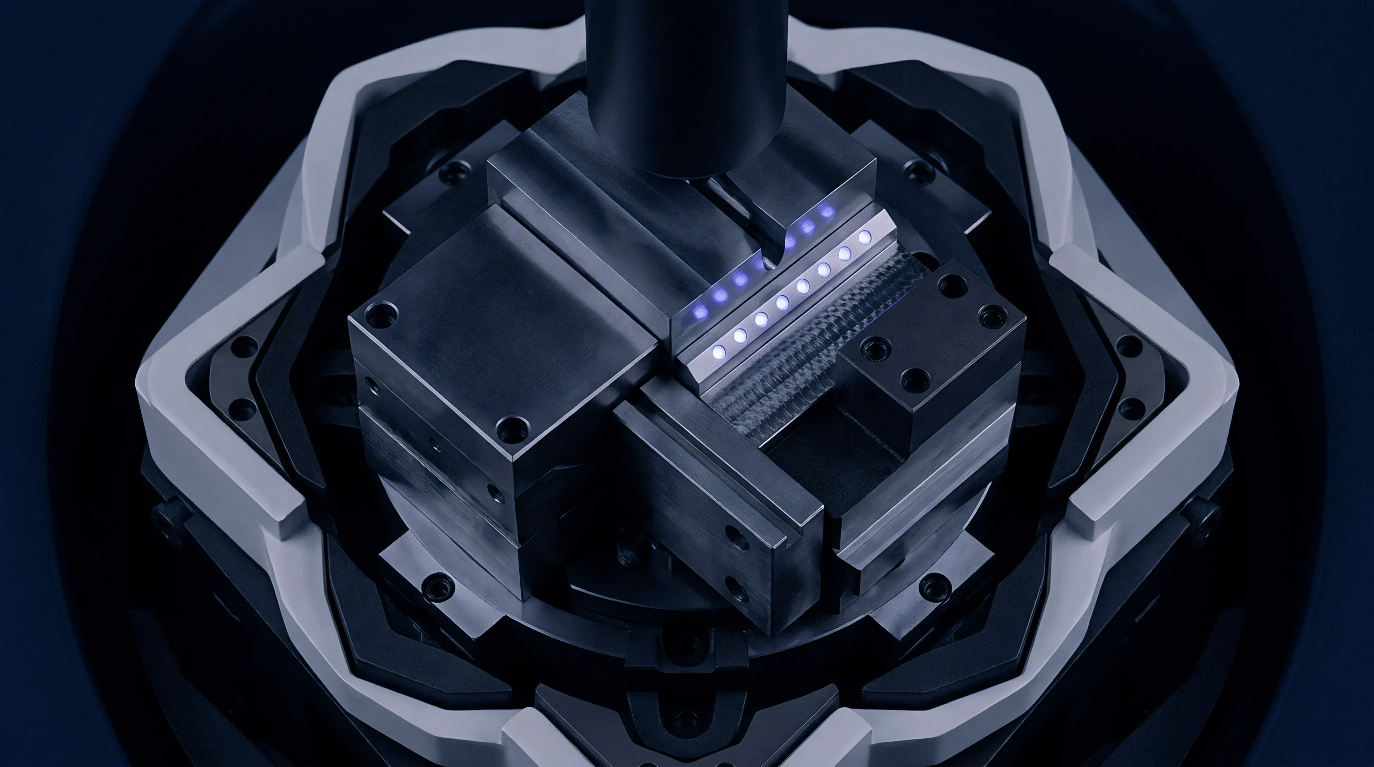
Distance offsets between measurement scales and tool contact points amplify angular deviations. Encoders measure position without strain data. When structural columns twist due to non-uniform conduction gradients, scale readings remain accurate at the encoder track while the tool tip deviates significantly in physical space.
Under ISO 230-3 testing standards, linear thermal growth across multi-axis frames must be decoupled from kinematic angular errors before verifying machine positioning budgets.
Standard quality protocols based on ISO 230-2 specify acceptance thresholds for machine tool accuracy under cold ambient environments, but standard compliance clauses fail to guarantee positional stability when machinery operates under dynamic pilot-scale thermal loads.

Compensation
Real-time mathematical filtering bridges the gap between encoder readings and physical tip positions. Dynamic error mitigation relies on spatial state-space models driven by distributed sensor networks. Fiber-optic Bragg grating sensors and contact temperature probes supply real-time thermal telemetry into computational models that update spatial offset matrices in real time.
Matrix inversion fails when sensors drift. Model-based compensation schemes must execute inverse kinematic algorithms within high-speed numerical control kernels to correct tool paths on the fly. Sensor drift or incomplete thermal state mapping introduces instability into offset calculations, generating unintended control chatter or compounding spatial deviation.

Can State Space Encoders Predict Volumetric Drift?
Digital twins integrating thermal network models evaluate real-time sensor streams to track tool tip motion. Sensor data feeds directly into reduced-order thermal state space equations that predict spatial deformation based on structural boundary conditions and real-time power consumption figures.
- Sensor array telemetry integration aggregates temperature inputs across high-friction drive mounts, structural casting ribs, and ambient environment boundaries.
- State space thermal estimation computes dynamic internal temperature profiles across unmeasured structural casting sections using reduced-order finite element formulations.
- Kinematic transformation calculation converts predicted structural strain matrices into real-time spatial offset vector maps across all kinetic degrees of freedom.
- Real time NC offset injection feeds inverse volumetric displacement coordinates into the numerical motion controller within sub-millisecond execution loops.
Real Time Edge Processing Protocols
On-machine hardware modules calculate state matrices within sub-millisecond execution cycles. High-frequency calculation prevents delay between physical thermal expansion and motion controller coordinate adjustment, keeping the tool tip locked on the targeted path.
Dynamic thermal compensation algorithms require continuous structural temperature inputs to maintain volumetric positioning accuracy within five micrometers under variable spindle loading.
How far can state-space predictive models reduce metrological positioning errors when machine tool castings experience transient, non-uniform thermal loading during rapid process acceleration?


Calibration
Direct physical measurement establishes absolute spatial benchmarks across machine envelopes. Dynamic metrological verification relies on multi-axis laser interferometers, double-ball bar systems, and tracking laser optics to quantify spatial position errors under active duty cycles. Conducting measurement sequences under thermal transient conditions reveals the precise magnitude of dynamic drift.

Laser Interferometer Spatial Baselines
Optical wavelength measurements quantify positional drift during duty cycle loading. Interferometers track linear displacement, pitch, and yaw simultaneously across axis travels, mapping spatial distortion as heat saturates the machine frame.
- Install multi-axis laser interferometer optics aligned parallel to the primary linear motion axes.
- Record cold baseline spatial positioning coordinates across the full volumetric envelope according to ISO 230-2.
- Engage the machine spindle and motion drives under high-speed pilot duty cycles for designated warm-up intervals.
- Capture dynamic axis positioning readings at fifteen-minute intervals to record thermal drift vectors.
- Compute dynamic volumetric error surfaces by subtracting cold baseline coordinates from dynamic thermal measurements.

Ball Bar Verification Cycles
Circular contour testing isolates squareness deviations under dynamic thermal equilibrium. Double-ball bar measurements capture planar contour distortions caused by thermal expansion differences between orthogonal feed axes.
Dynamic metrological verification must evaluate machine positioning errors under active operating temperatures rather than cold static ambient states.
When dynamic verification shows spatial positioning drift exceeding critical tolerance bands, baseline machine accuracy must be re-established under thermal equilibrium before signing off on scale-up readiness.

Tolerance
Pilot scale expansion requires tight limits on metrological error budgets to secure yield. Line speed drives linear thermal expansion. Scaling line speed without addressing thermal expansion gradients leads to high scrap rates and unexpected equipment downtime during capacity expansion phases.
Scale readiness demands explicit error bounds. Decoupling dynamic thermal expansion from multi-axis metrological errors establishes a predictable operational envelope, allowing high-speed pilot operations to scale seamlessly into full commercial production volumes.
Pilot Stage Gate Acceptance Limits
Expansion commitments depend on statistical process capabilities holding during high-speed production runs. Stage-gate criteria mandate that overall thermal positioning drift must consume no more than twenty percent of the total drawing tolerance during continuous high-speed execution.

Economic Impact of Metrological Drift
Out-of-spec pilot production lot costs scale exponentially as line speeds increase. Thermal error management directly protects profit margins by eliminating uncompensated dimensional drift before part features fall outside design specification limits.
Establishing control over thermal gradients ensures long-term operational viability across high-speed precision manufacturing processes. Rigorous metrological decoupling protocols safeguard capital investments and build reliable throughput capacity during pilot scale-up.