Coupled Thermo-Rheological Optimization of Conformal Cooling Geometries under Variable Wall Boundary Conditions
Coupled thermo-rheological optimization aligns conformal channel paths with polymer melt heat dissipation to compress cycle times and eliminate part distortion.

Melt
Inside an injection mold cavity, polymer behavior changes dramatically once shear rates spike past ten thousand inverse seconds. During the fill stroke, high molecular weight thermoplastics undergo pronounced non-Newtonian shear thinning, dropping dynamic viscosity by orders of magnitude compared to zero-shear baseline conditions. Localized fluid friction along the wall boundary generates sharp temperature spikes.
In rapid injection, this frictional heat frequently rivals or exceeds convective transfer into the cooling fluid. Calculating thermal profiles without accounting for temperature-dependent shear viscosity leads to major errors in predicting freeze-off timing and gate seal duration.
Rheological state equations must capture shear rate dependency alongside temperature sensitivity across the full processing window. The Modified Cross-WVF model describes both semi-crystalline and amorphous polymers, using parameters that define how melt viscosity shifts under local velocity gradients and thermal fields:
eta(gamma_dot, T, p) = eta_0(T, p) / (1 + (eta_0 gamma_dot / tau_star)^(1 – n))
Zero-shear viscosity eta_0 follows an exponential Arrhenius or Williams-Landel-Ferry dependence on temperature T and pressure p. Critical shear stress threshold tau_star marks the transition into non-Newtonian flow, while power-law index n sets the shear-thinning slope. When melt enters thin-walled mold sections at linear speeds above two hundred millimeters per second, localized shear heating raises temperature near the frozen layer by fifteen to thirty degrees Celsius.
Placing cooling channels close to the cavity wall alters this thermal boundary layer directly, shifting shear stress distribution through the cavity thickness and altering local flow resistance and pressure drop.
Melt front advancement depends heavily on heat conduction into the die steel. High-conductivity inserts draw heat rapidly from the freezing front, thickening the stationary polymer skin layer. That thicker skin narrows the open channel cross-section, driving up required injection pressures.
If cooling channels leave temperature variations along the cavity plane, skin thickness varies across the part geometry. This unbalanced skin formation creates asymmetrical flow paths, causing race-tracking, premature gate seal, and weld line defects. Shear rate gradients across uneven skin thicknesses also induce differential polymer chain orientation, locking residual stress tensor components directly into the solid matrix.
With semi-crystalline polymers, latent heat of crystallization complicates this thermal coupling. Polypropylene and polyamide resins release enthalpy during the phase transition from isotropic fluid to ordered crystalline domains, slowing local cooling between two hundred degrees Celsius and one hundred twenty degrees Celsius. Cooling layouts designed strictly for linear thermal conduction fail to account for the timing of this latent heat release.
Modeling this dynamic coupling accurately requires energy transport equations with explicit heat generation terms for both viscous dissipation and phase transformation enthalpy.
Viscous dissipation within high-speed injection gates raises local polymer temperatures by up to twenty-five degrees Celsius prior to cavity entrance.
Energy balances inside the flowing polymer melt resolve into a coupled transient partial differential equation. Convective enthalpy transport down the flow path competes against transverse heat conduction toward the mold walls and volumetric heat sources:
rho C_p (dT/dt + v grad(T)) = grad(k grad(T)) + eta gamma_dot^2 + q_dot_phase
Polymer density rho, specific heat capacity C_p, and thermal conductivity k all vary with local temperature and pressure. High-pressure volumetric shrinkage follows Tait pressure-volume-temperature relations, with density increasing ten to fifteen percent during solidification. Changing boundary conditions at the mold wall directly influence local heat flux q_wall, which relies on dynamic thermal contact resistance between the polymer skin and metal interface.
This resistance drops sharply during packing, then surges as cooling shrinkage pulls the solidifying plastic off the mold steel and forms air gaps.
Coupled rheological calculations show that adjusting channel depth alters temperature uniformity across cavity faces. Standard straight-drilled cooling lines leave wide thermal valleys between adjacent holes. Conformal channels, by contrast, mirror complex cavity contours to keep steel thickness consistent between coolant and polymer melt.
That uniform wall distance flattens surface temperature profiles and suppresses local viscosity swings during the fill stroke. As a result, the melt advances across uniform thermal fields with flat velocity profiles, preventing flow front distortion.
Flow stagnation occurs when polymer melt meets cold mold surfaces prematurely. Rapid chilling spikes local viscosity past press pressure limits, freezing movement before the cavity fills. Conformal channels mitigate stagnation by balancing heat removal along long flow paths.
Maintaining precise thermal control during filling keeps injection pressures within press limits and avoids flash from over-pressurization. Treating fluid rheology in isolation from transient boundary heat transfer risks miscalculating runner diameters, which can throw off clamp tonnage requirements by up to thirty percent.
Non-isothermal flow simulation demands simultaneous convergence of momentum, mass, and thermal balance equations at every time step. Wide viscosity ranges frequently yield stiff numerical matrices that trigger convergence failures. Near cavity walls, grid refinement must match the thermal boundary layer thickness, which often drops below fifty micrometers during initial melt contact.
Insufficient mesh density introduces artificial numerical damping that irons out real shear heating spikes. Capturing those spikes accurately determines whether tool designers specify localized core heating or accelerated conformal cooling layouts.
Viscous heating persists into the packing phase, where slow melt movement under extreme pressure continues to generate frictional energy. Gate freeze-off marks the transition from rheological flow control to pure solid conduction cooling. Miscalculating thermal dissipation before gate closure leads to inconsistent shot weights, dimensional drift across production shifts, and high reject rates during initial tool trials.
Ignoring viscous heat generation in non-Newtonian melt models distorts cavity pressure predictions, resulting in premature packing failures and severe part warpage.


Channel
Fluid conduit geometry within metallic tool inserts dictates overall heat extraction capacity. Traditional gun drilling restricts cooling channels to straight cylindrical passes, enforcing uniform hydraulic diameters regardless of surface contours. Additive manufacturing via Laser Powder Bed Fusion enables complex internal paths that follow three-dimensional cavity profiles.
Selecting target channel geometries alters local velocity profiles, pressure drops, and thermal boundary layer resistance.
Hydraulic performance in conformal cooling networks hinges on internal surface finish and cross-sectional geometry. As-printed additive channels exhibit surface roughness from ten to thirty micrometers Ra caused by partially fused metal powder. This roughness triggers an early transition to turbulence, driving friction factors well past classic Moody diagram predictions for smooth pipes.
The added friction increases pressure loss per unit length, demanding higher pumping pressure from temperature control units.

Geometric Profiles for Additive Tooling
Circular cross-sections remain standard because they distribute internal pressure symmetrically, though alternative shapes provide superior heat transfer. Teardrop profiles eliminate top overhang angles, allowing additive build cycles without internal support structures. Elliptical profiles present broader surface areas toward cavity faces, reducing thermal resistance through the steel.
Ribbed and twisted geometries introduce secondary swirl flows that disrupt boundary layers and elevate convective Nusselt numbers.
Pressure drop through conformal passages follows Darcy-Weisbach friction formulations adjusted for additive surface roughness. The friction factor f increases when relative roughness epsilon divided by hydraulic diameter D_h rises, elevating overall fluid pressure requirements across tool inserts:
Delta P = f (L / D_h) (rho_coolant v_coolant^2 / 2)
Cooling channels using water-glycol mixtures require turbulent flow to maximize heat extraction. Reynolds numbers must exceed ten thousand to guarantee fully developed turbulence. Lower flow rates yield laminar regimes where thermal resistance across fluid layers severely restricts heat removal.
Pumping capacity limits dictate maximum channel length before split-flow manifolds become necessary.
| Profile Geometry | Hydraulic Diameter (mm) | Nusselt Number Scaling | Pressure Drop per Meter (kPa) | AM Overhang Limit (deg) | Powder Removal Yield (%) |
|---|---|---|---|---|---|
| Standard Circular | 8.0 | 1.00 x Baseline | 42.5 | 45 | 99.5 |
| Self-Supporting Teardrop | 7.2 | 1.12 x Baseline | 58.1 | 65 | 98.8 |
| High-Aspect Elliptical | 6.5 | 1.28 x Baseline | 74.3 | 35 | 94.2 |
| Internal Helical Ribbed | 7.8 | 1.45 x Baseline | 112.6 | 40 | 91.5 |
Powder evacuation represents a primary constraint when printing intricate channels. Metal powder trapped inside narrow conduits can sinter during subsequent build cycles, blocking fluid passages entirely. Channel paths must maintain minimum bend radii of at least one point five times internal diameter to allow mechanical powder clearance via ultrasonic agitation and compressed air purging.
Post-print chemical etching or abrasive flow machining drops internal roughness below two micrometers Ra, reducing pressure losses by up to forty percent.

Pressure Loss and Hydrodynamic Head Constraints
Parallel cooling circuits balance overall pressure drop, but risk uneven flow distribution if circuit lengths or bend counts differ. Fluid follows the path of least hydraulic resistance, starving longer loops of adequate flow. These starved loops overheat during production runs, creating localized hot spots on cavity faces that delay part solidification and stretch overall molding cell cycle times.
Standard ISO 19011 tooling verification requires pressure-drop calibration across all parallel conformal loops prior to final tool sign-off.
Series cooling layouts eliminate flow starvation by forcing total fluid volume through a single continuous path. However, total pressure drop across long series runs frequently exceeds standard chiller pump limits of six bar. High backpressure cuts the overall volumetric flow rate, shifting fluid dynamics back into low-Nusselt transition regimes.
Designers must therefore divide complex inserts into balanced parallel sub-circuits fed by internal distribution manifolds.
Fluid velocity through conformal conduits must stay below five meters per second to prevent cavitation erosion along internal bends. Cavitation bubbles form in low-pressure separation zones downstream of tight turns, collapsing against metal walls and degrading channel surfaces over millions of cycles. Smooth transition elbows with radius-to-diameter ratios above two prevent localized flow separation, preserving structural integrity over extended production runs.
Wall thickness between cooling channels and mold cavity faces governs transient thermal response. Excessively thick steel walls create high thermal inertia, smoothing dynamic cooling cycles but slowing overall heat removal. Thin steel walls reduce thermal lag but risk structural deformation under peak injection pressures.
Tooling inserts must withstand cyclic cavity pressures exceeding twelve hundred bar without yielding or cracking into fluid passages.
While internal powder removal is specified as complete, post-build ultrasonic testing routinely uncovers trapped powder in tight channel bends that cuts design flow rates by half.


Dissipation
Heat transfer across mold boundaries is inherently transient, driven by cyclic contact with the polymer melt. Static boundary assumptions fail to capture the thermal spikes that occur during initial injection, where steel cavity surfaces experience rapid temperature rises of thirty to eighty degrees Celsius within milliseconds of contact. This is followed by gradual thermal decay through the packing and cooling phases.
Dynamic dissipation models must incorporate time-dependent boundary conditions to accurately predict solid fraction growth across part cross-sections.
Convective heat flux from die steel into the internal cooling fluid depends on local fluid properties, boundary layer thickness, and temperature differences. Wall heat flux q_wall varies continuously across the injection cycle:
q_wall(t) = h_fluid(t) (T_steel_wall(t) – T_coolant_bulk)
The convective heat transfer coefficient h_fluid depends on coolant flow regime, fluid density, heat capacity, thermal conductivity, and dynamic viscosity. As coolant properties vary with temperature, h_fluid shifts as energy is absorbed along the channel. Temperature rises along long circuits, reducing local thermal driving forces near channel exits and creating thermal gradients across cavity surfaces.
Transient Heat Transfer under Cyclic Wall Loads
Steel selection dictates how rapidly thermal energy diffuses away from mold surfaces. Premium H13 tool steel offers high hardness and wear resistance, but its thermal conductivity is relatively low at around twenty-nine Watts per meter-Kelvin. Maraging 300 steel delivers thermal conductivity near thirty-three Watts per meter-Kelvin along with excellent printability in Laser Powder Bed Fusion.
High-conductivity copper alloys, such as copper-chromium-zirconium, exceed three hundred Watts per meter-Kelvin, enabling rapid heat extraction from isolated core pins and narrow ribs.
Evaluating thermal diffusion performance across hybrid mold inserts combining Maraging steel structures with copper alloy core tips showed marked performance gains. This hybrid construction reduced surface temperature variance across deep core features from twenty-four degrees Celsius down to four degrees Celsius. The lower temperature spread eliminated local sink marks and compressed total cooling time from eighteen seconds to eleven seconds on thin-walled packaging components.
Is Multi-Objective Topological Filtering Necessary for Conformal Tooling?
Algorithmic geometry optimization generates intricate conduit networks that maximize heat removal while maintaining structural stiffness. Simple uniform cooling layouts rarely balance thermal dissipation against mechanical deflections driven by cavity pressure. Multi-objective topological filtering balances local Nusselt numbers against structural von Mises stress fields, preventing channel collapse under severe loading.
Unfiltered optimization schemes produce micro-channel structures with thin walls vulnerable to cyclic thermal fatigue. Repeated thermal expansion and contraction generate alternating stress states near cavity faces. Thermal stress range delta_sigma depends directly on local temperature fluctuations delta_T, steel elastic modulus E, and thermal expansion coefficient alpha:
delta_sigma = (E alpha delta_T) / (1 – nu)
High thermal stress ranges initiate low-cycle fatigue micro-cracks along grain boundaries, particularly near additive layer interfaces. These cracks propagate toward internal cooling channels, eventually triggering high-pressure fluid leaks into mold cavities during production runs.

Worked Thermal Shock and Heat Flux Calculation
Consider a flat cavity plate molding a four-millimeter thick polypropylene plate. Polymer melt enters the cavity at two hundred thirty degrees Celsius, with a target ejection temperature of ninety degrees Celsius. Upon melt contact, cavity surface temperature spikes from forty degrees Celsius to one hundred ten degrees Celsius.
Average heat flux density into the cavity steel reaches eight hundred fifty kilowatts per square meter during initial solidification.
Total heat energy Q_total extracted per cycle per square meter of cavity surface balances polymer enthalpy loss against thermal conduction into steel and convective removal by coolant:
Q_total = m_polymer (H_inject – H_eject) = integral(q_wall(t) dt)
At a production rate of six shots per minute, required thermal dissipation capacity equals eighty-five kilowatts per square meter of cavity face. Standard straight-drilled cooling channels positioned twenty-five millimeters behind cavity faces achieve a maximum steady-state dissipation density of fifty-two kilowatts per square meter. The resulting thermal deficit raises average mold temperature by six degrees Celsius per cycle until thermal equilibrium occurs at unacceptable surface temperatures.
By contrast, conformal channels positioned eight millimeters behind cavity faces sustain thermal dissipation densities exceeding one hundred ten kilowatts per square meter, maintaining steady mold temperatures under identical production cadence.
Dynamic thermal equilibrium requires balancing cyclic polymer enthalpy input against fluid heat extraction within each shot duration.
Variations in polymer wall contact resistance introduce unpredictable thermal boundary layer shifts. If gas entrapment occurs due to improper cavity venting, insulating polymer melt from steel surfaces, localized heat transfer drops by seventy percent. That drop leaves plastic unsolidified at nominal cycle completion, causing part deformation during pin ejection.
Precision tool designs combine conformal channels with high-permeability porous metal vents to maintain continuous mechanical and thermal contact along cavity boundaries.
Dynamic mold temperature control systems alter coolant supply temperature between injection and cooling phases. Pulsed cooling circulates high-temperature water during injection to reduce shear stress and eliminate weld line defects, then switches rapidly to chilled water for accelerated solidification. Dynamic switching introduces severe transient thermal loads on channel walls, accelerating mechanical degradation if channel corners contain sharp fillet radii.
Tooling supply agreements adhering to DIN 16742 dimensional standards mandate maximum wall temperature variance limits of five degrees Celsius across cavity faces, automatically invalidating delivery sign-offs when thermal imaging reveals uncorrected hot spots.

Topology
Mathematical geometry optimization transforms conformal cooling design from intuitive drafting into deterministic computational physics. Adjoint sensitivity formulations calculate derivative gradients of objective functions with respect to spatial domain boundaries. Algorithms then adjust channel coordinates, cross-sectional profiles, and branching layouts to minimize thermal variance while holding fluid pressure drop within set bounds.
Topology optimization treats spatial domains as continuous density fields ranging from zero to one, where a density of one represents solid die steel and zero represents open cooling fluid channels. Solid Isotropic Material with Penalization schemes scale local material properties, driving intermediate density values toward discrete binary states. Governing partial differential equations for fluid dynamics and heat conduction execute simultaneously across the design domain.
Adjoint Formulation for Coupled Systems
Coupled thermo-rheological adjoint methods calculate sensitivity vectors across complex flow networks without needing individual numerical solves for every geometry tweak. Objective function J balances temperature field variance across mold cavity boundaries against fluid power dissipation across cooling circuits:
J = w_1 integral((T_cavity – T_target)^2 dS) + w_2 integral(delta_P Q_fluid dV)
Weighting factors w_1 and w_2 establish priorities between thermal uniformity and pumping energy. Optimization solvers evaluate continuous adjoint state variables to update boundary positions along gradient descent directions, running iterative loops until objective change rates drop below defined convergence thresholds.
Fluid flow equations within adjoint loops use Brinkman-extended Navier-Stokes formulations to represent porous media transitions between fluid channels and the solid metal matrix. Brinkman penalty terms penalize velocity vectors inside solid steel zones, steering fluid movement strictly through optimized channel pathways. Computational grids require high spatial resolution along fluid-solid interfaces to prevent artificial thermal blurring.

Constraint Boundary Selection in Tool Design
Geometric constraints prevent optimization algorithms from generating non-printable features. Additive manufacturing via Laser Powder Bed Fusion requires strict overhang angle limits to avoid internal support structures, so optimization routines incorporate geometric filter constraints that restrict downward-facing surface angles to values greater than forty-five degrees relative to build plates.
Minimum wall thickness constraints prevent channels from being placed too close to cavity surfaces or ejector pin holes. Thin metal walls yield under peak injection pressures, causing structural tool failure. Distance constraints maintain minimum steel margins of three to five millimeters between internal channels and secondary machining features.
Lattice structure infills offer an alternative optimization outcome, replacing solid die steel with porous periodic structures. Hollow tool interiors filled with optimized lattice networks reduce insert mass while enabling multi-directional coolant flow. Cooling fluid moves directly through structural lattice matrices, maximizing heat exchange surface area per unit volume.
Fluid manifold branching follows natural drag-minimization patterns resembling vascular networks. Branching junctions introduce local pressure drop penalties if split angles are chosen incorrectly. Constructal law principles guide optimal bifurcation angles, balancing wall shear stress against total fluid volume flow.
Calculated topology outputs require geometry smoothing before translation into computer-aided design solids and additive build prep files. Raw density fields produce faceted, pixelated mesh boundaries that create localized stress concentrations. Laplacian smoothing and Non-Uniform Rational B-Spline surface fitting convert discrete topology voxels into smooth, manufacturable tool geometries.
Optimization convergence challenges arise when non-Newtonian melt rheology interacts with dynamic thermal boundary conditions. Non-linear coupling causes objective functions to develop multiple local minima. Genetic optimization algorithms and hybrid particle swarm methods explore global design spaces before gradient-based adjoint solvers refine final channel boundary positions.
Computational overhead for fully coupled three-dimensional transient adjoint optimization remains substantial. HPC clusters running parallel spatial decomposition methods require dozens of wall-clock hours per design iteration. Simplified steady-state thermal approximations reduce solve times but risk misjudging peak thermal loads during transient production cycles.
What structural stress threshold dictates the minimum allowable wall distance between high-pressure conformal channels and mold cavity faces under cyclic loads?
Metrology
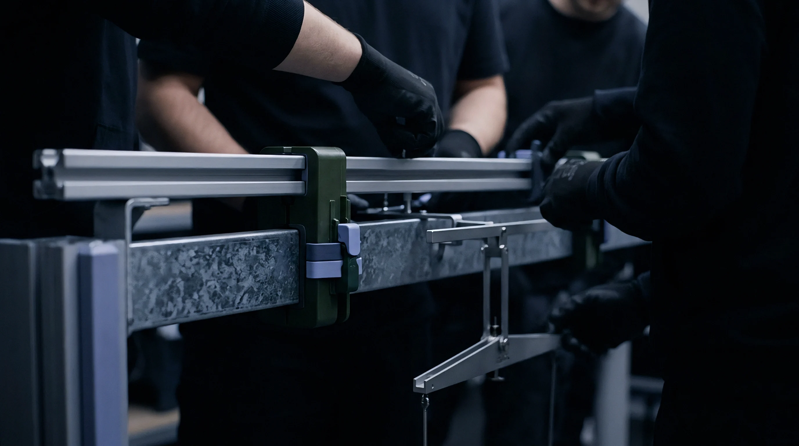
Physical measurement systems validate whether manufactured conformal cooling inserts perform to computational models. Additive manufacturing tolerances, internal surface finishes, and powder clearance steps require strict inspection before tool installation. Diagnostic testing detects structural flaws, flow blockages, and heat removal discrepancies long before inserts enter serial production.

In-Situ Sensor Placement and Transient Verification
Flush-mounted piezoresistive pressure transducers and fast-response thermocouples installed inside mold cavity faces capture real-time thermal profiles. Signals recorded at millisecond intervals yield empirical cavity surface temperature curves during injection, packing, and cooling phases. Deviations between measured temperature decay and simulated curves signal internal channel anomalies or incorrect heat transfer coefficients.
Infrared thermography audits evaluate surface temperature uniformity across entire tool inserts during dry-cycling checks. Dynamic thermal imaging highlights localized hot spots caused by clogged channels or uneven wall distances. Quantitative thermography then maps thermal variance across cavity faces, confirming compliance with specification limits.
Ultrasonic thickness gauges verify remaining steel margins between internal conduits and complex cavity contours. Non-destructive ultrasonic testing measures sound wave transit times through die steel, detecting wall thinning caused by post-print chemical polishing. Accurate wall thickness maps prevent catastrophic tool failure during initial high-pressure injection trials.

Defect Logging and Non-Destructive Inspection
Industrial Computed Tomography scanning provides complete three-dimensional visualization of internal channel geometry. X-ray CT inspection identifies powder remnants, voids, micro-cracking, and layer delamination inside printed metal inserts. Quantitative CT metrology compares printed channel coordinates against nominal CAD models, capturing dimensional shifts introduced during thermal stress-relief annealing.
- Flow Rate Baseline Verification establishes baseline fluid volume throughput across defined pressure drops, identifying macro-scale flow restrictions inside printed circuits.
- Transient Thermal Response Audit measures cavity surface cooling speed following standardized radiant heat pulses, confirming convective heat removal capability.
- Hydrostatic Pressure Leak Testing pressurizes internal cooling channels to double maximum operating limits for extended durations, proving structural joint integrity.
- Infrared Cavity Mapping captures two-dimensional thermal uniformity maps across mold faces during rapid thermal cycling, verifying computational optimization predictions.
| Inspection Method | Measured Parameter | Acceptance Criterion | Failure Mode Identified |
|---|---|---|---|
| Industrial X-Ray CT | Channel Geometry & Internal Voids | Deviation < 0.15 mm from CAD | Sintered Powder Obstructions |
| Differential Flow Testing | Pressure Drop vs Flow Rate | Delta P within 5% of design curve | Channel Wall Roughness Spikes |
| High-Pressure Hydrostatic | Pressure Decay Rate | Zero drop at 12 bar for 30 min | Inter-Layer Additive Cracking |
| Dynamic Infrared Imaging | Surface Temperature Uniformity | Max thermal spread < 3.0 °C | Cooling Circuit Flow Starvation |
Flow calibration rigs measure pressure drop versus volumetric flow rate curves for every parallel cooling circuit. Discrepancies between parallel loops indicate internal channel roughness variations or partial powder blockages. Automated test stands reject tool inserts that fail to meet tight flow balance specifications.
In-line coolant telemetry monitors supply and return temperatures alongside continuous flow meters during active molding operations. Heat absorption rates calculated from temperature differentials confirm total heat extraction performance. Early detection of flow rate decay alerts plant operators to scale deposition or biological fouling inside internal channels before part quality suffers.
Optical borescope inspections evaluate internal surface finishes within accessible channel sections. Micro-cameras passed through distribution channels identify surface pitting, crack initiation sites, and post-processing chemical residue. Documented visual inspection logs support tooling warranty claims and quality management audits.
Metrology data feeds back into design optimization pipelines, closing the loop between predicted simulation performance and printed reality. Empirical surface roughness profiles replace assumed Moody values in subsequent computational fluid dynamics runs, improving future design accuracy.
Cooling channel metrology relies on verifying flow rate balance across parallel circuits before mounting printed inserts into production mold bases.


Valuation
Capital investment in conformal cooling tooling requires clear financial justification anchored by production capacity gains. Additive manufacturing of tool inserts using Laser Powder Bed Fusion increases initial tooling costs by three to five times relative to conventional gun-drilled steel blocks. Financial payback depends on compressing molding cycle times, reducing scrap rates, and eliminating secondary post-processing steps across volume production runs.
Capital Outlay and Cycle Time Payback
Cycle time reduction serves as the primary economic driver for adopting conformal tooling. Cooling phases typically consume fifty to seventy percent of total injection molding cycle duration. Compressing cooling time by twenty to forty percent increases hourly part output from existing presses, deferring capital expenditure for additional machinery and floor space expansion.
Consider an automotive molding line producing two million structural components annually across four injection presses. Conventional tooling operates at a thirty-five second cycle time, with twenty-two seconds dedicated to cooling. Conformal cooling inserts cut cooling time to twelve seconds, dropping total cycle time to twenty-five seconds.
Output per press surges by forty percent, allowing three presses equipped with conformal tooling to match the annual output of four conventional presses and eliminating one complete press work cell from expansion plans.
| Annual Volume (Units) | Conventional Cycle Time (s) | Conformal Cycle Time (s) | Tooling Capital Premium ($) | Payback Period (Months) |
|---|---|---|---|---|
| 100,000 | 45.0 | 32.0 | 18,000 | 22.4 |
| 500,000 | 45.0 | 31.5 | 22,000 | 5.1 |
| 1,000,000 | 45.0 | 30.0 | 28,000 | 2.8 |
| 2,500,000 | 45.0 | 29.5 | 35,000 | 1.2 |
Scrap rate reductions deliver secondary savings by eliminating thermal warpage defects. Asymmetrical cooling across mold cavity faces creates uneven residual stress fields, causing flat parts to bow or twist beyond engineering tolerances upon ejection. Conformal cooling maintains uniform mold surface temperatures, suppressing differential shrinkage and dropping warpage scrap rates from three percent down to under zero point two percent.
Sequential Gate Checklist for Tooling Approval
Tooling procurement requires clear stage-gate criteria to manage technical and commercial risks before committing capital expenditure. Project managers verify operational requirements before signing off on additive manufacturing purchase orders.
- Validate coupled thermo-rheological simulation models against physical resin viscosity data to confirm predicted cycle time compression numbers.
- Audit additive manufacturing supplier capabilities, verifying Laser Powder Bed Fusion equipment calibration, metal powder quality certificates, and non-destructive CT inspection capabilities.
- Enforce mechanical stress margin checks, ensuring internal cooling channels maintain minimum five-millimeter clearances from high-pressure cavity boundaries.
- Execute flow rate and pressure drop calibration tests on all printed inserts before assembling inserts into final mold bases.
- Verify thermal image uniformity maps during full-speed production trials, confirming mold cavity face temperature variations stay below three degrees Celsius.
Energy consumption per molded part drops when cycle times shrink. Press hydraulic pumps, barrel heating bands, and cell automation consume electrical power continuously during operation. Reducing cycle duration spreads fixed machine operating power over larger production volumes, lowering electrical energy cost per part by fifteen to twenty-five percent.
Tool wear and maintenance costs must enter long-term valuation calculations. Additive tool steels like Maraging 300 exhibit lower corrosion resistance than stainless tool steels such as 420 or 1.4416. Cooling fluid filtration and chemical rust inhibition treatment become mandatory operating expenses to prevent internal channel scaling and pitting corrosion.
Budgeting routine chemical cleaning cycles prevents premature tool performance degradation over multi-million shot production lifespans.
Capital allocation decisions weigh additive tooling risks against operational headroom gains. High-volume consumer packaging, medical device, and automotive programs amortize additive tooling premiums rapidly across large production runs. Low-volume specialty runs rarely generate sufficient cycle time savings to recover initial additive fabrication outlays, making conventional gun-drilled tooling the financially sound choice.
Sequential sign-off protocols protect capital outlays by binding tooling supplier milestone payments to empirical performance metrics. Final procurement clearance requires documented proof of pressure drop compliance, internal powder clearance verification, and thermographic cavity uniformity confirmation during site acceptance testing.