Separating Machine Thermal Expansion from Mechanical Repeatability
Isolating thermal growth from mechanical repeatability separates deterministic expansion from stochastic hysteresis, preventing false machine tool calibration.
Drift
Precision machine tools exhibit positioning variations caused by continuous temperature changes and fundamental mechanical drive play. Isolating these two sources of dimensional deviation determines whether an axis off-target condition demands mechanical overhaul or environmental stabilization. Mechanical non-repeatability stems from friction, wear, bearing axial play, guideway stick-slip, and backlash within recirculating ball screws.
Thermal drift arises from ambient air variations, structural temperature gradients, spindle motor heat generation, and frictional heating along linear guideways during axis travel.
Friction generates heat.
Mechanical non-repeatability manifests as high-frequency, non-deterministic scatter or hysteresis across short timeframes. Thermal growth develops as a smooth, low-frequency dimensional change occurring over hours of continuous operation. Confounding these mechanisms results in incorrect machine calibrations.
Adjusting controller pitch-error compensation tables to correct for an unheated ball screw creates position errors once the drive reaches operating temperature.

Thermal Elongation Mechanics
Heat generation within internal machine components expands structural elements along defined linear axes. The spindle assembly, axis drive motors, bearing blocks, and ball screws serve as primary heat sources. Steel expands predictably.
A carbon steel ball screw expanding under continuous high-speed movement changes its physical length proportionally to the temperature rise. When direct linear scale feedback is absent, the machine controller relies on rotational encoder counts, translating physical lead screw growth directly into component dimensional error. Cast iron machine beds bend and twist when thermal gradients develop between the front and rear structural walls.
These structural distortions alter spindle orientation relative to the work table, shifting the tool center point in three-dimensional space.
Mechanical Backlash and Hysteresis
Drive system lost motion arises from physical clearances in ball nuts, gear meshes, and support bearings. Static calibration ignores friction heat.
When an axis reverses direction, mechanical clearance must be traversed before motion transfers to the slide table. This hysteresis remains constant regardless of machine run time, provided mechanical wear stays minimal. Preload loss increases mechanical play.
Guidance system stick-slip occurs when static friction exceeds dynamic friction during micro-stepping movements, causing discontinuous positioning jump phenomena. These mechanical faults produce localized, reproducible offset bands that occur instantly during motion reversal, presenting signatures entirely distinct from gradual heat growth curves.
| Error Parameter | Thermal Expansion Source | Mechanical Repeatability Source |
|---|---|---|
| Time Horizon | Gradual shift across minutes to hours | Instantaneous upon motion or direction reversal |
| Behavior Pattern | Continuous monotonic curve approaching steady state | Stochastic scatter bounded by hysteresis envelope |
| Reversibility | Requires structural cooling cycle to reverse | Reverses immediately upon direction stroke change |
| Structural Location | Distributed along ball screws, beds, and columns | Concentrated at joints, bearings, and nut interfaces |
| Feedback Sensitivity | Mitigated by linear glass scale direct feedback | Mitigated by preloaded linear bearings and ball nuts |
Disentangling mechanical wear from ambient or operational heat sources requires structured isolation steps. The list below outlines structural components and their primary positioning error classifications.
- Recirculating Ball Screws Elongate axially from friction heat, producing linear scale factor positioning errors across the total travel length.
- Spindle Cartridge Bearings Expand axially and radially during rotation, shifting tool height and tilt relative to the machine table workpiece fixture.
- Axis Support Bearings Develop axial endplay under wear, causing immediate direction-reversal hysteresis independent of operating temperature.
- Linear Guide Carriages Experience preload loss under structural wear, generating random lateral displacement scatter during cutting force loading.
- Cast Iron Columns Incur asymmetric thermal gradients from sun exposure or shop air flows, inducing column tilt and Abbe alignment errors.
The machine tool vendor attributes dimensional variances exceeding five micrometers to ambient HVAC air cycling rather than mechanical ballscrew preload loss.

Metrology
Isolating thermal growth from pure mechanical uncertainty requires distinct measurement protocols executed across timed operational cycles. Standard positioning calibration performed immediately after machine startup records mechanical backlash combined with an unheated structural frame state. Executing identical measurement runs after four hours of continuous axis exercise captures the total combined thermal displacement and mechanical scatter.
Comparing cold baseline data against warm operational data isolates deterministic expansion from stochastic mechanical play.
Cold tests show baseline play.
Displacement sensors, contactless eddy-current probes, and multi-axis laser interferometers capture raw positioning data. Laser interferometers measure linear displacement, pitch, yaw, and roll variations along an axis path. Mounting optical retroreflectors on the machine slide table maps positioning deviations across full travel strokes.
Comparing laser readings against controller target values highlights thermal scale changes when repeated at timed intervals.
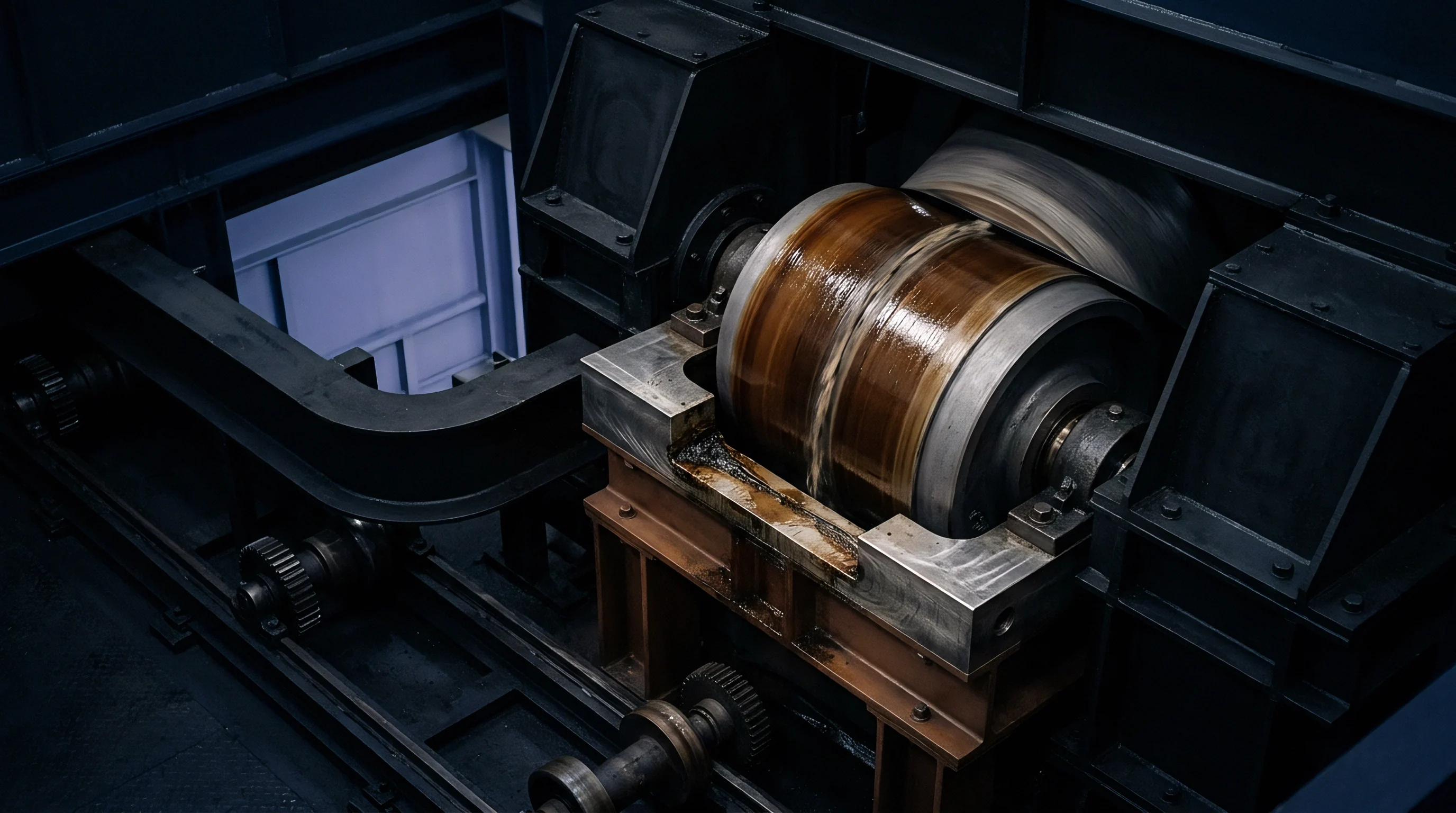
Laser Interferometry and Sensor Arrays
Non-contact linear displacement devices measure structural movement relative to stable physical reference points. Contactless capacitance or eddy-current sensors fixed in an artifact block track spindle nose growth across three orthogonal axes. Placing an invar test arbor in the spindle nose eliminates tool holder thermal variations during drift evaluation.
Backlash remains constant.
Positioning error ruins tight tolerances. Thermal offset shifts position. Measuring displacement continuously over six hours while running the spindle at maximum operational speed isolates spindle growth from axis drive movement.
Temperature sensors attached to the spindle housing, column frame, ball nut, and ambient air correlate physical expansion directly to localized heat accumulation.
Measuring machine positioning variation at fixed thermal states isolates deterministic axial growth from stochastic mechanical backlash.
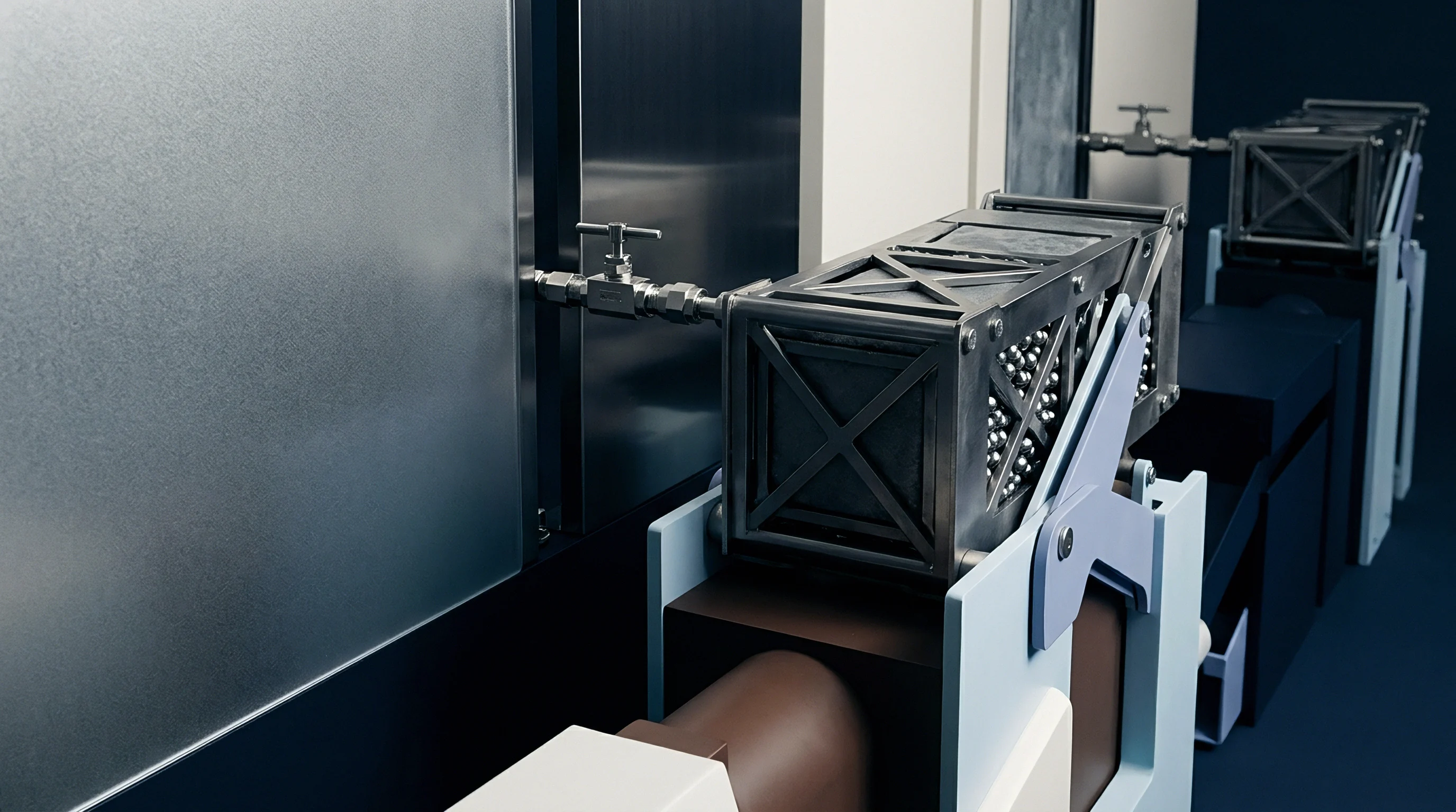
Decoupling Test Protocol
A standardized multi-stage test runs axis motion under controlled temperature states. The following plain numbered sequence isolates mechanical hysteresis from operational thermal drift without soft software compensation intervention.
- Stabilize the machine environment at twenty degrees Celsius for twelve hours with all internal heat sources powered down.
- Mount a low-expansion invar line standard or laser interferometer parallel to the axis travel path.
- Execute ten rapid bi-directional positioning cycles across five target positions to calculate baseline mechanical bi-directional repeatability and backlash under cold conditions.
- Engage the axis drive in rapid traverse cycles across eighty percent of total travel for sixty minutes to induce friction heating.
- Pause movement immediately and re-run the ten bi-directional positioning cycles across the same target positions.
- Record position offset shifts while subtracting the baseline mechanical backlash value established in step three.
- Repeat the rapid motion and measurement cycle hourly until structural temperature sensors indicate thermal steady-state conditions.
Mistaking mechanical bearing backlash for thermal expansion leads to invalid offset adjustments that ruin workpieces as soon as the spindle reaches thermal equilibrium.

Kinematics
Mathematical modeling of axis expansion relies on linear thermal growth coefficients combined with geometric lever arms. Simple axial growth models evaluate linear expansion using the structural material coefficient, original reference length, and measured temperature delta. Machine tool structures present complex thermal expansion pathways where structural joints, material interface boundaries, and non-uniform thermal fields produce non-linear bending moments.
Direct encoders reduce hysteresis.
Abbe errors amplify small angular thermal tilts into large linear position offsets at the tool point. An angular tilt of five arcseconds caused by column thermal distortion produces an offset of twenty-four micrometers at a tool tip located one meter from the guide axis. Calculating total tool point position shift requires combining linear expansion equations with angular transformation matrices.
Which Error Signature Dominates Machine Position Drift?
Distinguishing between deterministic growth trends and random mechanical scatter demands spectral time-series analysis of axis position data. Mechanical scatter appears as stationary white noise centered around a mean value, whereas thermal growth appears as a non-stationary low-frequency drift trend. Statistical process capability evaluations (Cp and Cpk) split when thermal drift drives process mean shifts.
While Cp reflects pure short-term mechanical spread, Cpk degrades continuously as structural growth pushes tool position toward tolerance limits.
Positioning accuracy degrades by eight micrometers per meter for every single degree Celsius of uncompensated structural temperature change on cast iron frames.
Axis Expansion Worked Calculation
Evaluating a high-speed ball screw axis provides concrete bounds for expansion magnitude versus mechanical uncertainty. Assume a carbon steel ball screw with an effective length of 1000 millimeters, a coefficient of thermal expansion of 11.7 × 10⁻⁶ K-1, and a measured baseline mechanical hysteresis of 3 micrometers.
Friction heating raises the average ball screw temperature from a cold baseline of 20 degrees Celsius to an operating temperature of 30 degrees Celsius (Δ T = 10 K). The physical length change calculates as:
Δ L = α · L · Δ T
Δ L = (11.7 × 10⁻⁶ K-1) · (1000 mm) · (10 K) = 0.117 mm = 117 μm
Thermal growth across the 1000 millimeter stroke equals 117 micrometers. The mechanical hysteresis remains fixed at 3 micrometers. The thermal growth magnitude exceeds baseline mechanical non-repeatability by thirty-nine times over this operational range.
Attempting to eliminate the 117 micrometer offset by mechanical backlash adjustment damages drive components, whereas using indirect rotational feedback without dynamic thermal compensation guarantees dimensional part rejection.
Whether real-time finite element modeling integrated directly into CNC controllers can predict multi-axis thermal bending without physical displacement feedback remains an open operational question.

Isolation
Controlling shop environment fluctuation reduces structural thermal distortion before soft software corrections apply. Precision machining facilities maintain ambient air temperatures within narrow bands, typically twenty degrees Celsius plus or minus half a degree. Direct sunlight, external doorway drafts, and adjacent HVAC discharge vents create localized temperature variations across machine columns, degrading structural symmetry.
Thermal equilibrium takes hours.
Chillers regulate spindle temperature. Fluid cooling loops circulating temperature-controlled liquid through spindle housings and hollow ball screws extract internal friction heat at the generation site. Linear glass scales manufactured from zero-expansion materials, such as quartz glass or specialized alloys, supply absolute physical position feedback directly to the controller, bypassing ball screw thermal elongation completely.
Compliance with ISO 230-3 clause six invalidates supplier thermal claims if ambient room temperature varies by more than one degree Celsius per hour during verification testing.
Structural Pre-Loading and Active Temperature Control
Physical design choices attenuate thermal distortion before software compensation steps engage. Symmetrical machine frame designs route thermal expansion along neutral structural axes that do not alter tool-to-workpiece alignment. Pre-tensioned ball screws anchored firmly at both support bearings transform thermal elongation into internal compressive stress, preventing physical length growth across operating temperature ranges.
Glass scales measure true position.
Active compensation software uses temperature sensor network arrays attached across the machine casting. Polynomial algorithms map measured localized temperatures to empirical tool offset correction values. These algorithms update offset registers in real time, shifting coordinate systems to counter measured thermal growth.
Compensation System Implementation
Algorithmic correction maps require periodic validation against laser measurement standards. The decision checklist below outlines critical steps required when commissioning physical thermal control and software compensation systems.
- Direct Scale Integration Mount optical linear scales with ultra-low thermal expansion coefficients to decouple axis control loop positions from drive screw expansion.
- Fluid Thermal Management Install closed-loop chillers tracking ambient shop temperature to maintain spindle and coolant oil within one half degree Celsius.
- Sensor Array Placement Embed thermistors at primary structural friction nodes including drive bearings, ball nuts, motor mounts, and column casting bases.
- Empirical Mapping Verification Perform laser interferometer calibration runs across step-temperature increments to validate mathematical polynomial correction matrix coefficients.
- Pre-program Warm-up Sequences Implement mandatory automated spindle motion routines before cutting tolerance-critical part features after idle machine shifts.
A machine axis verified cold delivers false precision until the spindle motor and coolant system achieve steady thermal state.

Stipulation
Machine procurement specifications mandate explicit performance boundaries for bi-directional repeatability under controlled and uncontrolled thermal states. Factory acceptance tests require clear separation between cold mechanical positioning limits and long-term thermal drift tolerances. Vague supplier guarantees promising low positioning uncertainty often fail on production floors when tested across full operational shifts.
Measurement timing changes the result.
Contracts specify precise testing standards, including ambient room temperature stability requirements during verification runs. Standard ISO test methodologies define exact motion cycles, dwell times, and sensor locations to prevent vendors from masking thermal drift behind rapid short-stroke testing.
Acceptance Standards and Capability Verification
Standardized test specifications establish legally binding metrics for axis performance verification. ISO 230-2 governs positioning accuracy and repeatability determination for numerically controlled axes under stable thermal conditions. ISO 230-3 measures environmental thermal effects and thermal distortion generated by internal heat sources during extended spindle and axis operation.
| Standard Designation | Primary Target Parameter | Key Test Methodology |
|---|---|---|
| ISO 230-2 | Bi-directional positioning accuracy, systemic backlash, and repeatability | Quasi-static laser measurement across full stroke under thermally stable conditions |
| ISO 230-3 | Thermal distortion from spindle rotation and linear axis motion | Continuous non-contact sensor monitoring during high-speed exercise cycles |
| ISO 230-7 | Geometric accuracy of axes of rotation and spindle thermal drift | Precision sphere and probe readings capturing radial, axial, and tilt motion shifts |
Formal machine qualification protocols mandate evaluating Cpk capability indices using parts machined across full shift transitions. Equipment failing thermal isolation tests requires mechanical adjustments, active chilling retrofits, or environmental containment before formal sign-off acceptance.
Execution of ISO 230-2 clause 4.2 obligates the machine vendor to demonstrate bi-directional positioning repeatability before thermal compensation software applies soft corrective values.