Metrological Profiling of Joint Deflection and Dynamic Forklift Wheel Loads
Dynamic forklift wheel impact across concrete floor joints drives arris spalling when vertical joint deflection under loaded axles exceeds half a millimeter.
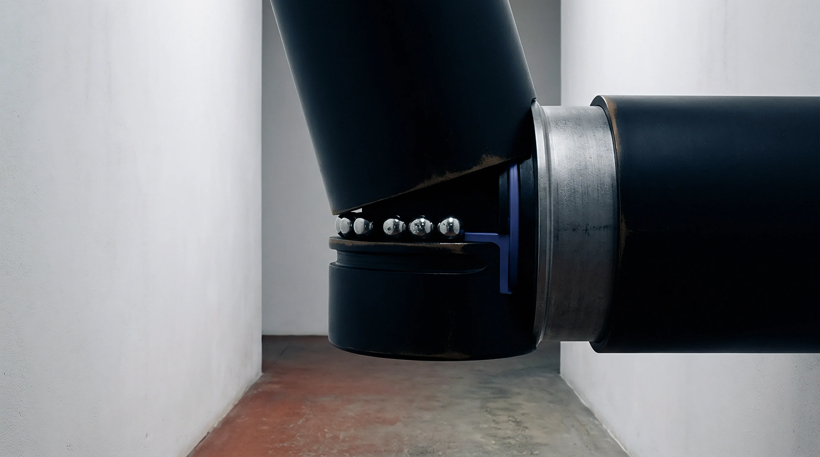

Axle
Industrial fork trucks exert concentrated vertical forces on concrete ground slabs that far exceed nominal static wheel loads. Static load calculations allocate vehicle deadweight and rated mast capacity evenly across axle baselines. Operational acceleration, emergency braking, and load elevation alter mass distribution across front drive wheels.
When a fully loaded fork truck stops abruptly, load transfer shifts up to eighty-five percent of total vehicle and payload weight onto the front drive axle.
Solid tires amplify kinetic force. Polyurethane and solid rubber compounds deform minimally under pressure, transmitting high frequency shock waves straight into the slab surface. Pneumatic tires absorb impact energy through air compression, whereas hard synthetic wheels transfer transient force directly into joint arrises during wheel passage.

Kinetic Force Generation across Wheel Contact Patches
Contact area between a solid wheel and a concrete surface shrinks as tire durometer increases. High-durometer polyurethane tires create a small footprint, resulting in localized contact stresses reaching ten to fifteen megapascals. Solid tires amplify kinetic force.
Moving load profiles exhibit peak dynamic amplification factors between 1.25 and 1.80 depending on vehicle velocity, floor roughness, and wheel hardness. Small diameter load wheels on reach trucks deliver severe stress spikes because their small radius drops sharply into opened slab joints.
| Tire Material Compound | Shore Hardness | Contact Stress Range (MPa) | Dynamic Load Factor Range |
|---|---|---|---|
| Soft Pneumatic Rubber | 60 Shore A | 0.8 – 1.5 | 1.10 – 1.25 |
| Solid Press-On Rubber | 75 Shore A | 2.5 – 4.5 | 1.20 – 1.40 |
| High-Capacity Polyurethane | 95 Shore A | 8.0 – 12.5 | 1.35 – 1.65 |
| Vollcollan / Cast Nylon | 70 Shore D | 12.0 – 18.0 | 1.50 – 1.90 |

Dynamic Mass Transfer during Heavy Lift Acceleration
Hoisting heavy pallets at height introduces overhead moment forces that alter chassis stability. Mast tilt movements create rapid shifting of wheel load centers. Accelerating forward with a elevated load transfers weight toward the rear steer axle, but braking shifts that weight forward onto narrow drive wheel contact patches.
Wheel contact pressure drives degradation. When front drive wheels cross a floor expansion or contraction joint, the leading edge of the receiving slab panel absorbs a rapid kinetic impact.
- Determine static front axle deadweight and maximum payload rating from vehicle manufacturer data sheets.
- Calculate dynamic mass transfer during maximum deceleration using truck center-of-gravity height and wheelbase geometry.
- Apply tire durometer shock multipliers based on wheel material stiffness and floor operating surface profile.
- Determine maximum transient single wheel load for joint structural shear capacity comparison.
A three-millimeter vertical joint deflection under a six-tonne wheel impact reduces dowel fatigue life by sixty percent when joint opening width exceeds fifteen millimeters.
Selecting floor slab designs without accounting for transient axle load factors causes severe joint edge breakdown, leading to repeated tire replacement costs and emergency slab rebuilds.
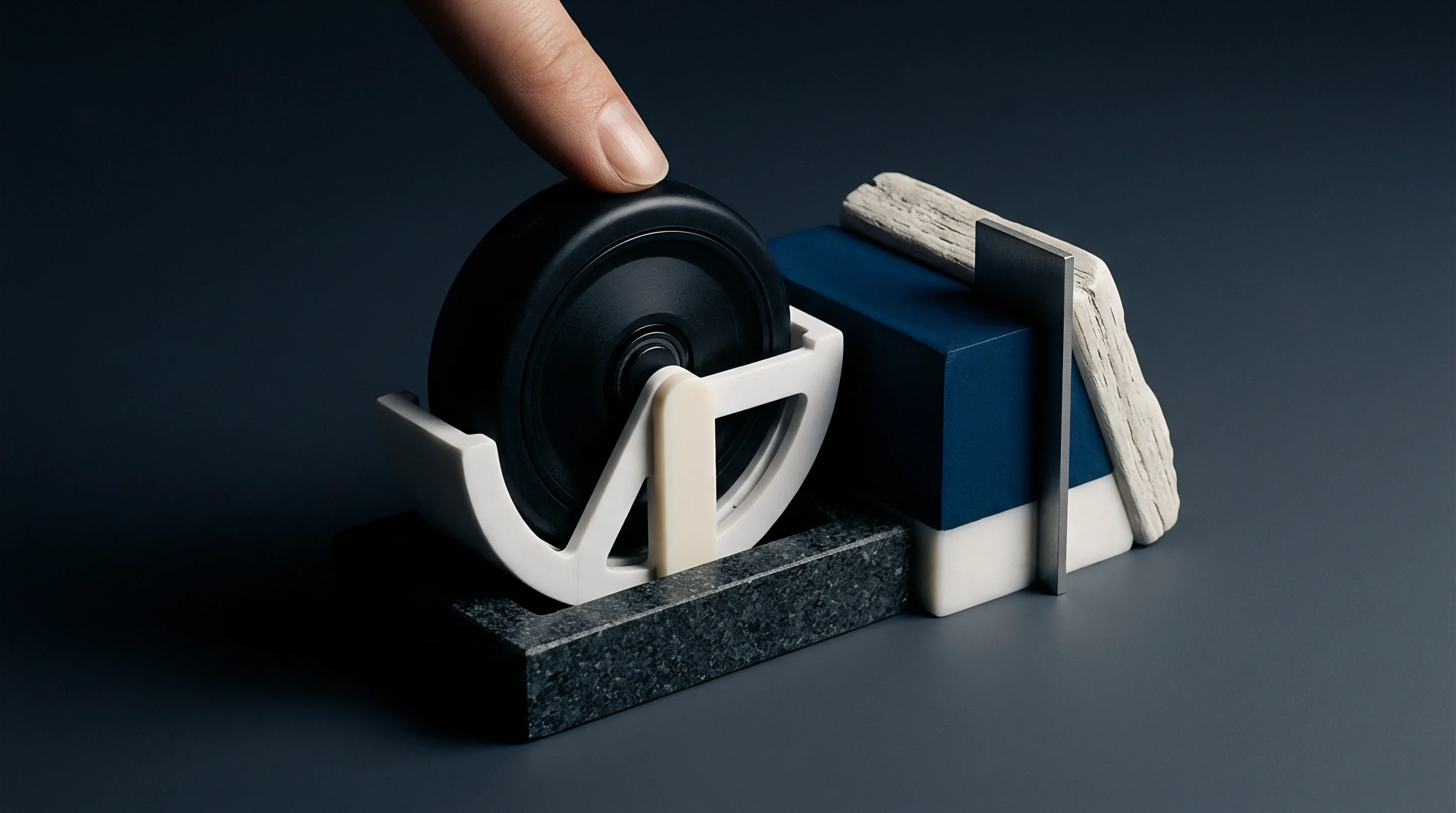
Dowels
Shear transfer mechanisms across concrete floor joints maintain surface continuity under heavy moving traffic. Un-doweled aggregate interlock joints lose structural efficiency as thermal shrinkage expands joint gaps beyond one millimeter. Steel dowel bars and plate dowels bridge sawcut gaps, transferring vertical load from the loaded slab panel to the adjacent unloaded panel.
Deflection degrades structural stability. When shear transfer devices experience excessive clearance or concrete crushing inside dowel pockets, differential vertical displacement occurs during wheel passage.
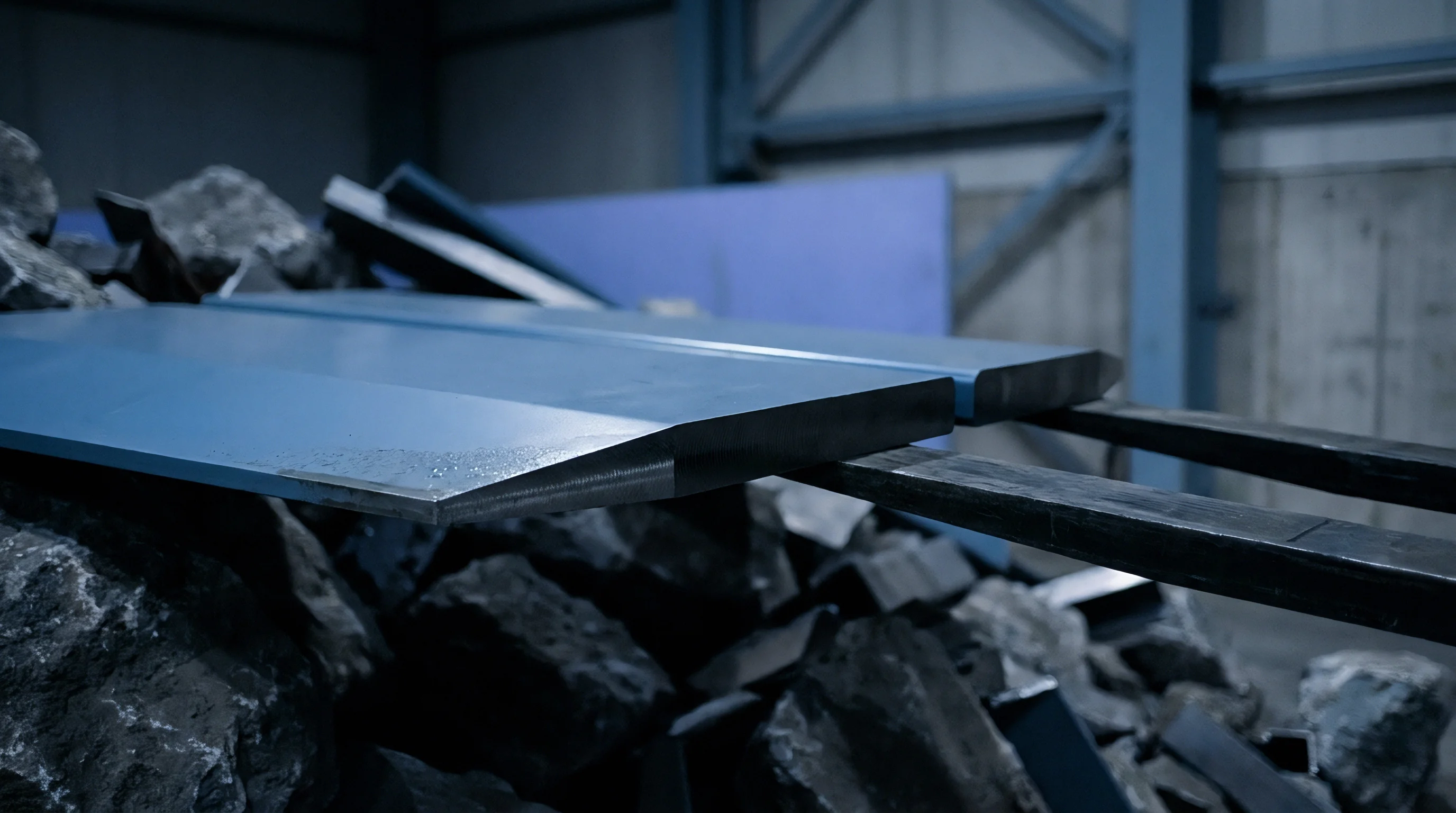
Structural Shear Transfer Mechanics across Slab Cut Openings
Round dowels concentrate bearing stresses along top and bottom concrete contact lines, leading to localized micro-cracking under repetitive heavy axle passes. Plate dowels present a wider bearing surface, reducing concrete contact stress and allowing lateral slab movement during thermal cycles. Dowel sleeves prevent concrete bonding.
Load Transfer Efficiency measures joint performance as the ratio of unloaded slab deflection to average joint deflection multiplied by two hundred percent. A fully effective structural joint yields ninety percent efficiency, whereas an efficiency rating below sixty percent indicates advanced shear mechanism degradation.
Compliance with TR34 Fourth Edition specifies maximum allowable vertical differential deflection of 0.5 millimeters to prevent joint arris spalling and vehicle chassis damage.
Slab Edge Curling and Void Formation beneath Subgrade
Differential drying shrinkage creates upward curling at slab panel edges and corners. Top surface concrete loses moisture faster than bottom concrete exposed to subgrade vapor barriers. Edge uplift detaches slab undersides from soil subbases, creating beneath-slab voids up to three millimeters deep.
Uncontrolled joint motion accelerates spalling. As heavy forklift wheels approach an un-supported curled edge, the slab cantilevers downward until making contact with underlying subbase material.
- Slab Arris Micro-Fracturing occurs when vertical differential movement forces hard polyurethane wheels to strike un-supported concrete joint edges.
- Dowel Sleeve Grouting Breakdown develops under high localized bearing stresses that crush surrounding concrete paste inside dowel pockets.
- Subgrade Erosion Pumping manifests when repeated vertical joint deflections force trapped liquid and fine particles out through sawcut openings.
- Plate Dowel Punching Shear initiates when thin concrete sections above or below dowel pockets fracture under high wheel shock loads.
Equipment vendors often state that joint edge chipping stems entirely from excessive forklift operating speeds rather than structural shear transfer loss across slab dowels.

Instrumentation
Accurate profilometry across active floor joints necessitates dynamic measurement tools capable of capturing millimeter-scale vertical displacements at high sampling frequencies. Static floor flatness meters measure inclination over fixed distances but fail to capture transient joint deflections under moving wheel loads.
Optical sensors measure transient deflection. Dial indicators anchored to reference beams yield static deflection numbers, but digital transducer arrays provide real-time profiling during actual forklift transit.
High Frequency Sensor Arrays for Dynamic Profilometry
Linear Variable Differential Transformers attached across sawcuts measure relative vertical displacement between adjacent slab panels. High-speed laser displacement gauges mounted on trailing test rigs record joint profile movement at sampling rates exceeding one kilohertz.
Profilometer arrays collect elevation data. Synchronizing transducer readings with axle position sensors maps vertical joint deflection directly to wheel load passage.
| Sensor Modality | Sampling Frequency | Measurement Resolution | Operational Field Complexity |
|---|---|---|---|
| Contact LVDT Transducer | 2.0 kHz | 0.001 mm | High fixture setup time required |
| Non-Contact Laser Displacement Sensor | 5.0 kHz | 0.005 mm | Moderate calibration effort |
| High-Speed Optical Camera Profilometer | 1.0 kHz | 0.010 mm | Low mechanical setup complexity |
| Piezoelectric Accelerometer Array | 10.0 kHz | 0.020 mm | Complex numerical integration required |
| Data captured during controlled pass-over tests using a six-tonne drive axle operating at ten kilometers per hour. | |||
Calibration Standards for Continuous Surface Profiling
Metrological profiling tools require strict calibration against standardized optical optical flat blocks before field operations. Temperature variations within industrial facilities expand metal mounting frames, introducing bias into displacement records.
Laser displacement gauges require periodic recalibration to compensate for surface reflectivity variations across concrete surfaces and joint sealants. Subgrade pumping removes structural support.
Polyurethane wheels concentrate dynamic force onto concrete joint edges far more aggressively than pneumatic tires of equal capacity.
Adopting ASTM E1155 profile measurement protocols with local joint deflection extensions changes contract acceptance thresholds from static flatness values to loaded structural displacement limits.

Fatigue
Repetitive wheel load passages induce progressive material degradation inside joint assemblies. Cumulative mechanical stress weakens both concrete joint arrises and subgrade support structures over operational lifespans.
Base compaction dictates slab stiffness. Microscopic voids beneath joint edges enlarge under cyclic loading, increasing vertical joint motion over time.
Cycle Accumulation and Shear Transfer Degradation
Dowel-concrete contact zones undergo crushing fatigue under high cyclic shear forces. Tensile micro-cracks propagate outward from dowel pocket corners toward slab surfaces, reducing overall shear capacity.
Vertical displacement exceeds static calculations. Slab curling expands joint openings. As joint sawcut width increases due to concrete drying shrinkage, dowel bending length grows, increasing flexural stress inside steel dowels during wheel passes.

Worked Calculation of Differential Deflection Growth
Consider a ten-ton forklift operating across an open contraction joint with a twenty-kilonewton single wheel load. Initial metrological profiling establishes an un-loaded joint gap of six millimeters and an initial Load Transfer Efficiency of eighty-five percent. Initial differential vertical deflection measures 0.35 millimeters under test axle transit.
After five hundred thousand wheel passes, concrete crushing surrounding dowel sleeves expands mechanical play inside dowel sockets by 0.40 millimeters. Subgrade erosion lowers soil support beneath panel edges by an additional 0.50 millimeters. Recalculating vertical load distribution yields a degraded Load Transfer Efficiency of forty-eight percent.
Differential vertical displacement increases to 1.15 millimeters under identical load conditions. Edge failure damages industrial tires.
| Accumulated Axle Cycles | Joint Opening Width (mm) | Load Transfer Efficiency (%) | Differential Deflection (mm) |
|---|---|---|---|
| 10,000 | 3.0 | 92% | 0.15 |
| 100,000 | 4.5 | 81% | 0.38 |
| 250,000 | 6.0 | 65% | 0.72 |
| 500,000+ | 8.0 | 42% | 1.45 |
Sustained operation above one millimeter differential deflection initiates rapid arris spalling and structural breakdown.
- Deflection Profile Datasets recorded across high-traffic joint lines under standardized test axle loading.
- Subgrade Void Acoustic Records proving spatial extent of beneath-slab loss of support adjacent to joint edges.
- Wheel Hardness Audit Certificates documenting durometer ratings for all operating material handling equipment.
- Joint Gap Thermal Movement Logs tracking seasonal expansion and contraction variations across structural bays.
Continuous profiling reveals load transfer failure weeks before visual spalling appears at slab surface joints.
Harder tire compounds driven over wider joint gaps degrade underlying subgrade support far faster than soft elastic wheels passing over tight structural joints.
Repair
Restoring joint integrity necessitates intervention methods that re-establish shear transfer and eliminate underlying subgrade voids. Surface patch repairs fail quickly if structural vertical deflections remain uncorrected.
Arris failure destroys lift wheels. Epoxy mortars fill surface chips, but structural joint stabilization requires under-slab grouting or retrofit dowel installations.
Subgrade Void Injection and Pressure Grouting
Polyurethane structural resins injected through drilled slab ports expand to fill subgrade voids. High-density resin foams exert upward pressure, re-establishing soil contact and restoring support to curled slab corners.
Drilling grid patterns along joint margins enables controlled resin placement. Real-time laser profiling monitors slab elevation during injection to prevent over-lifting panel edges.
Armored Joint Reconstruction and Retrofit Systems
Severely damaged joint arrises require full-depth sawcutting and removal of spalled concrete sections. Heavy steel armor profiles anchored into fresh high-strength concrete provide impact protection against hard polyurethane wheels.
Dowel bar retrofits install heavy plate dowels into precision-cut slots across existing joint lines. Mechanical anchors lock retrofit assemblies into adjacent concrete panels, restoring structural load transfer efficiency.
Whether post-installed dowel retrofits can maintain long-term shear load transfer efficiency under continuous heavy forklift traffic without causing secondary punching shear fractures along the sawcut line remains an open technical debate.