Dynamic Shut Height Compensation for Thermal Drift in High Speed Press Ram Mechanics
Active wedge mechanisms eliminate dynamic thermal drift in press rams, stabilizing bottom dead center to protect progressive tooling and hold tight burr tolerances.

Swell
High speed mechanical presses cycling between 600 and 1200 strokes per minute convert mechanical friction and metal deformation into significant heat. Crankshaft journal bearings, pitman wrist pins, slide guide gibs, and counterbalance cylinders release thermal energy directly into the cast iron frame and forging steel components. The ram body expands downward while the upright columns expand upward.
Operating lines experience an immediate drift in mechanical shut height as the temperature of structural elements climbs thirty degrees Celsius above ambient plant levels during the initial four hours of stamping.
Thermal expansion alters penetration depth inside progressive dies. A temperature elevation of twenty degrees Celsius along a forged steel connecting rod measuring eight hundred millimeters yields an axial elongation of approximately one hundred ninety microns. Die punch penetration into strip stock shifts by that exact amount unless counteracted by machine mechanics.
Precision blanking tools for electrical motor laminations operate with total punch-to-die clearances between eight and fifteen microns. Uncontrolled vertical drift drives punches deeper into carbide die cavities, causing premature tool chipping, catastrophic shear edge fracture, and excessive burr height on finished stamped laminations.
A thermal climb of twenty-four degrees Celsius inside four cast steel uprights extends press frame height by one hundred forty microns under steady four-hundred-stroke operation.
Lubricating oil absorbs frictional heat. Circulating lubrication reservoirs without active chillers distribute thermal loads throughout the press bed, bolster plate, and side housings. As lubricant heats from twenty-five degrees to fifty-five degrees Celsius, oil viscosity drops by more than sixty percent.
Thinner fluid films diminish the damping capacity of hydrodynamic bearings, inducing additional mechanical vibrations that accelerate thermal energy transfer across precision mating faces.

Thermal Gradients across Structural Press Columns
Cast iron frames and forged steel tie-rods absorb heat unevenly during prolonged production runs. Upright columns facing drafty aisleways lose thermal energy faster than rear columns shielded by electrical enclosures and drive guards. The resultant differential expansion produces angular tilt across the slide plate.
When the rear uprights expand fifty microns more than the front uprights, the ram faces bottom dead center with a measured parallel misalignment exceeding 0.05 millimeters per meter. This angular tilt shifts lateral thrust directly onto brass gib liners, accelerating localized wear patterns and creating binding risks along the vertical slide path.
Heat accumulates rapidly during high speed stamping. The internal balance of structural forces relies on symmetric thermal fields across all four corners of the bed. Plant managers monitoring high volume lines observe distinct heat sinks:
- Upper crown assemblies trap hot lubricant returning from eccentric shafts, generating localized expansion zones that crown the top crosshead upward away from the die bed.
- Recirculating hydraulic oil lines radiate convective heat along the rear press columns, setting up front-to-back thermal deltas that tilt the slide face out of parallel.
- Frictional friction clutch assemblies discharge thermal spikes during repeated inching cycles, dumping shock heat directly into flywheel hub bearings and press side frames.
- Scrap chute apertures channel cold ambient air drafts across lower bolster plates, creating rapid vertical gradients between hot upper tool holders and cold die bases.

Kinematic Heat Sources in Ram Linkages
Main crankshaft bearings, eccentric bushings, and wrist pins experience continuous sliding contact. Friction inside sleeve bushings generates thermal loads proportional to line stroke velocity and operating press tonnage. Hydrodynamic oil film breakdown generates localized contact temperatures exceeding eighty degrees Celsius under extreme production cadences.
Thermal conduction travels downward through the suspension screws and pitman links directly into the ram block.
Thermal equilibrium arrives late. Full mechanical equilibrium frequently demands six to eight hours of uninterrupted stroking at rated speeds. Production interruptions for coil changes or strip thread-ups cause rapid cooling of the tooling and slide faces while internal frame cores remain hot.
Resuming production after a twenty-minute pause forces the press mechanism through an inverted thermal cycle, producing out-of-tolerance parts until internal temperatures stabilize. Press builders frequently tell plant engineers that forty minutes of dry cycling before shift startup solves all dimensional variations.
Sensor
Measuring bottom dead center displacement at operating rates exceeding 800 strokes per minute exposes hardware to massive deceleration loads. Contact probes shatter within minutes under fifty-gravity acceleration spikes common to high speed mechanical presses. Non-contact position monitoring techniques isolate structural ram positions relative to the lower bolster plate during the critical reversal zone of the stroke.
Positioning systems capture vertical displacement at bottom dead center with single-micron repeatability across millions of continuous operating cycles.
Sensors degrade under harsh vibration. Optical scales and laser interferometers lose tracking capability when atomized stamping oil mists accumulate on protective glass lenses. Inductive eddy current transducers resist dielectric fluid contamination and mechanical shocks up to five hundred gravities.
These probes mount directly within the lower die shoe or machined pockets inside the press slide guides, reading against hardened target plates on opposing structural faces. Signal conditioning units sample probe outputs at frequencies exceeding one hundred kilohertz, capturing transient displacement profiles within a three-degree crank angle window around bottom dead center.
| Measurement Technology | Resolution Window | Sampling Frequency | Operating Temperature Drift | Environmental Survival Limit |
|---|---|---|---|---|
| Eddy Current Transducers | 0.5 microns | 100 kHz | 0.10 microns per degree C | Resistant to stamping oils and shock loads to 500g |
| Confocal Chromatic Optical Probes | 0.1 microns | 30 kHz | 0.02 microns per degree C | Sensitive to oil vapor and mist accumulation |
| Linear Encoders with Invar Scales | 0.2 microns | 50 kHz | 0.05 microns per degree C | Requires sealed enclosures with positive air purge |
| Piezoelectric Strain Rings | 1.0 microns | 200 kHz | 0.25 microns per degree C | Vulnerable to thermal pyroelectric voltage drift |
Position errors compound across hours. Mechanical clearance collapses. Signal processors extract valid bottom dead center displacement points by analyzing peak signal amplitudes precisely when the crank angle resolver indicates one hundred eighty degrees.
Analog output signals feed industrial controllers through dedicated high speed fieldbus networks, eliminating electrical noise generated by nearby variable frequency motor drives and uncoiler servo drives.
A production standard establishes that displacement sensors must hold calibration across eighty million load reversals without exceeding one micron of electronic signal drift.

Eddy Current and Laser Triangulation Benchmarks
Inductive displacement probes mounted directly into die shoes target reference targets on the upper tooling plate. Direct in-die sensing records actual punch-to-die proximity rather than structural frame positions, bypassing the mechanical compliance of the press slide, pitman arms, and bed bolsters. Laser triangulation heads mounted externally on press uprights provide broad spatial monitoring of frame distortion, though atmospheric heat shimmers and airborne oil mist deflect laser beams by several microns over half-meter path lengths.
Thermal stability within sensor mounting fixtures requires specialized low-expansion alloys. Fixtures machined from standard carbon steel expand at eleven microns per meter per degree Celsius, introducing artificial measurement errors that mask press expansion. Mounting brackets fabricated from Invar or ceramic zero-expansion glass ceramics decouple the sensing probe from the thermal growth of the host machine frame.
Placement Geometries for Real Time Measurement
Tooling engineers position monitoring hardware within four guide pillars to isolate tool deflection from gib clearance. Placing probes symmetrically across four corners of the upper die set permits real-time calculation of both absolute shut height and slide tilt angles. Differential math models run on digital signal processors, subtracting symmetric structural compression from true thermal growth to prevent erroneous compensation movements during heavy stamping impacts.
A persistent operational question concerns whether structural sensors on the press columns can ever predict punch penetration depth as accurately as direct in-die transducers during variable tonnage blanking runs.

Wedge
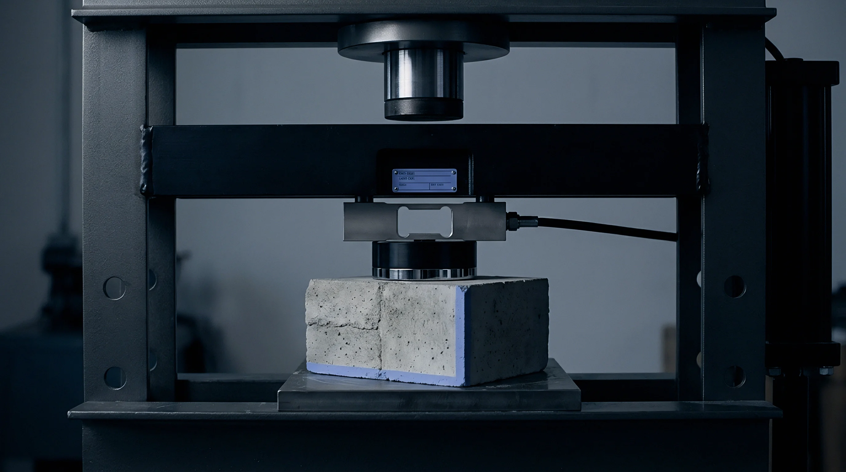
Mechanical adjustment assemblies restore nominal bottom dead center position while stamping presses cycle at full capacity. Traditional motorized shut height adjusters relying on coarse screw threads inside the pitman linkages cannot adjust under full operational loads due to severe friction across loaded thread flanks. High speed presses integrate micro-wedge mechanisms between the slide base and the tooling attachment face.
Opposed wedge blocks ground to taper angles between two and five degrees translate lateral motion into micro-scale vertical displacement, allowing continuous shut height correction against opposing forming forces.
Stamping tool longevity relies directly on mechanical compensation speeds exceeding the thermal expansion rate of the drive train.
Wedge motors demand stiff gearboxes. High torque servomotors turn low-backlash ball screws that slide the driving wedge laterally across needle roller packs. A horizontal wedge travel of ten millimeters translates to a vertical ram adjustment of three hundred fifty microns at a two-degree inclination angle.
This mechanical advantage allows compact servo packages to shift slide height against three hundred tons of dynamic stamping resistance without stalling the actuator mechanics.

Is Mechanical Wedge Correction Faster than Servo Adjustments?
Opposed inclined planes actuated by secondary electric drives alter the effective length of the suspension points within milliseconds. A direct mechanical wedge system shifts tool position during the non-contact upstroke window of the press cycle. When a press operates at nine hundred strokes per minute, a single stroke completes in sixty-six milliseconds, providing a non-forming return window of roughly thirty milliseconds.
Mechanical wedge actuators complete increment adjustments of one to two microns within that twenty-millisecond idle stroke window, eliminating transient side loads across tooling guide pins.
Servo eccentric bushings provide an alternative compensation route. Rotating an eccentric sleeve positioned between the crankshaft and the connecting rod bearing alters the effective center distance of the kinematic linkage. High-torque brushless motors drive the outer eccentric sleeve through planetary reduction gearing, advancing or retarding nominal bottom dead center position without stopping the main flywheel rotation.
Eccentric sleeves preserve extreme mechanical rigidity, avoiding the localized compliance introduced by stacked wedge assemblies under violent snap-through shock profiles.
Operators set up closed-loop adjustment systems through an exact procedural sequence:
- Zero the mechanical wedge blocks at baseline room temperature before mounting progressive tooling.
- Establish baseline bottom dead center positions using static lead wire crush readings across four corners.
- Engage the high speed fieldbus link between in-die displacement probes and the wedge servo drive.
- Lock out manual shut height overrides to prevent concurrent mechanical inputs during automatic thermal compensation.

Motorized Tie Rod Prestress Tuning
Hydraulic nuts mounted atop the press crown vary tensile clamping force to expand or contract the frame. By modulating hydraulic pressure behind high-tonnage tie rod cylinders, controllers induce controlled elastic deformation within the four main uprights. Raising hydraulic tie rod tension compresses the frame columns, lowering the crown and reducing shut height by thirty to eighty microns.
Thermal compensation systems adjust oil volume via high-speed proportional valves, executing frame corrections without moving physical sliding wedges beneath the ram.
Incorrect wedge positioning during live stroke corrections shifts cutting punches laterally into die matrix sidewalls, destroying carbide punch edges and generating tens of thousands of dollars in tooling replacement expense.


Deflection
Elastic elongation of structural members combines with thermal expansion to shift actual tooling penetration depth. A mechanical press does not behave as a rigid assembly under load. When a three-hundred-ton press blanks high-strength strip, the crankshaft deflects downward, the side uprights stretch upward, and the bolster plate sags elastically.
Dynamic deflection at bottom dead center scales directly with instantaneous forming tonnage, counteracting thermal expansion that simultaneously drives the ram downward.
Stamping tonnage spikes uncontrollably. Carbide punches crack under overload. When thermal expansion lowers the ram by forty microns, punch penetration into the strip increases.
Greater penetration through work-hardening steel elevates peak blanking tonnage by fifteen to twenty-five percent. Higher tonnage increases the elastic structural stretch of the frame, pushing the ram back upward during the moment of maximum fracture. Thermal drift and structural deflection form an interactive mechanical loop that destabilizes blanking consistency.
DIN EN ISO 6892-1 material testing standards verify that yield strength spikes across work-hardened strip directly amplify press frame elastic deflection during blanking.
Consider a typical high speed press running electrical motor laminations. The machine operates at eight hundred strokes per minute with a nameplate rating of two thousand kilonewtons. Total structural height of the four forged steel columns equals three meters.
Ambient temperature starts at twenty degrees Celsius. After four hours of continuous stamping, bearing friction warms the ram linkages to fifty degrees Celsius while the structural columns reach thirty-five degrees Celsius. Column thermal expansion equals 11.5 microns per meter per degree Celsius multiplied by three meters multiplied by a fifteen-degree rise, yielding an upward frame expansion of 51.75 microns.
Linkage thermal expansion drives the ram downward by 98 microns. Net thermal shut height change equals a downward shift of 46.25 microns.
Strip thickness variance worsens error. A five percent increase in incoming strip thickness from nominal 0.35 millimeter silicon steel elevates forming resistance, increasing instantaneous dynamic frame elongation from one hundred twenty microns to one hundred thirty-five microns. If the active compensation system misinterprets dynamic elastic deflection as thermal expansion, the controller moves the mechanical wedge in the wrong direction, compounding positional deviation.
Filtering algorithms must separate cyclical elastic deflection, which occurs within milliseconds at stroke frequency, from slow thermal drift occurring across hundreds of continuous cycles.
| Operating Duration | Frame Column Thermal Drift | Linkage Thermal Expansion | Peak Dynamic Elastic Deflection | Net Uncompensated Position Shift |
|---|---|---|---|---|
| Start (0 Hours) | 0.0 microns | 0.0 microns | +115.0 microns | 0.0 microns |
| 1 Hour | +18.5 microns | -38.0 microns | +122.0 microns | -19.5 microns |
| 2 Hours | +34.0 microns | -69.5 microns | +128.0 microns | -35.5 microns |
| 4 Hours (Equilibrium) | +52.0 microns | -98.0 microns | +134.0 microns | -46.0 microns |
| Methods note: Positive values indicate upward frame growth away from bed; negative values indicate downward ram advance toward bed. Deflection read under 1800 kN peak blanking loads. | ||||

Will Closed Loop in Process Compensation Prevent Die Failure?
Continuous feedback algorithms compare measured bottom dead center against calibrated target values every stroke. When the moving average of displacement drifts outside a two-micron deadband, the controller signals the mechanical wedge actuator to advance or retract. Feed-forward mathematical models calculate anticipated thermal expansion based on temperature sensors embedded in the crankshaft bearings and upright columns, pre-positioning the slide before thermal growth alters part geometry.
Engineers evaluate active compensation hardware against rigid production requirements:
- Actuator frequency response must exceed the speed of continuous thermal accumulation while rejecting cyclic tonnage disturbances.
- Thermal sensor distribution covers internal bearing shells, external column surfaces, and circulating oil manifolds without leaving dead zones.
- Control algorithm deadbands prevent constant hunting of the servo motor that induces mechanical fatigue inside the adjustment screw threads.
- Data logging capabilities track bottom dead center position against part inspection records to verify machine capability during qualification audits.

Punch Penetration Variance in Thin Foil Lamination
Progressive stamping dies for motor core laminations operate with cutting clearances under five microns. Die wear accelerates past noon. Punches penetrating deeper than twenty percent of sheet thickness into high-silicon electrical steel experience intense abrasive wear and abrasive welding along tool flanks.
Excessive punch entry also pushes blanked material deeper into the die matrix, increasing stripping friction during the upstroke and triggering punch breakage.
Optical lens manufacturing presents an analogous physical constraint where micro-positioning drives must isolate multi-axis thermal expansion from high-frequency structural resonances to preserve sub-micron focal geometries. Stamping press rams execute identical sub-micron stability under dynamic impact environments.
Standard purchase contracts for high speed press lines incorporate ISO 10791-7 acceptance clauses, enforcing strict verification that closed-loop shut height compensation maintains bottom dead center repeatability within three microns across eight continuous hours of full-speed dry cycling.

Yield
Tool wear, burr height, and part flatness quantify the operational payoff of tight bottom dead center control. Progressive dies costing hundreds of thousands of dollars produce millions of motor laminations between sharpening cycles only when punch penetration depth stays within narrow process windows. Thermal shut height drift destroys tooling economics by causing premature punch wear, forcing unbudgeted die maintenance and slashing gross press line utilization across production facilities.
Tolerances tighten on electrical laminations. Stator core efficiency hinges directly on edge quality and magnetic properties. Excessive punch penetration fractures the insulating coating along the edge of electrical steel sheets, generating interlaminar short circuits that spike eddy current losses inside electric vehicle traction motors.
Maintaining shut height within a four-micron envelope extends carbide die life from two million strokes to eight million strokes between regrinds.
Scrap Rates and Stamping Burr Thresholds
Electrical steel laminations destined for traction motor stators permit edge burrs of ten microns maximum. When thermal drift allows punches to strike deeper into the die opening, cutting edges round over, increasing shear clearance and triggering burr formation exceeding twenty-five microns. Automated inspection stations reject defective laminations downline, turning expensive coil inventory into low-value scrap metal and stranding capacity across downstream core stacking lines.
Precision dies forgive zero collisions. Scrap accumulation halts line output. Modern stamping plants operate with tightly coupled automation where an out-of-tolerance burr height stalls automated robotic welding and interlocking stations.
Real-time shut height compensation eliminates the root cause of dimensional variation, stabilizing scrap rates below 0.1 percent across multi-million-part automotive delivery contracts.
Capital Allocation and Retrofit Payback Windows
Plant controllers evaluate active shut height systems against the landed cost of replacement progressive carbide dies. A typical progressive lamination tool demands substantial capital investment and six months of fabrication lead time. Premature tool wear driven by uncompensated thermal drift consumes carbide punch length in regrinding operations, shortening tool operating lifespan by more than half.
Refitting older mechanical presses with active micro-wedge adjustments and eddy current feedback loops costs a fraction of a new high speed press replacement. Operations leaders balance equipment retrofit timelines against incoming contract volume requirements, setting clear go-conditions based on historical tooling spend and client burr tolerances.
A reliable rule of thumb dictates that if daily die maintenance logs show punch regrinds driven by uneven flank wear rather than normal abrasive dulling, the press mechanism is suffering from uncompensated thermal shut height drift.