Long Shift Dimensional Variance Mitigation under Variable Lubrication Schedules and Continuous Thermal Loading Dynamics
Mitigating long-shift dimensional drift requires isolating viscous lubrication drag and structural thermal growth through real-time CNC offsets and metered dosing.
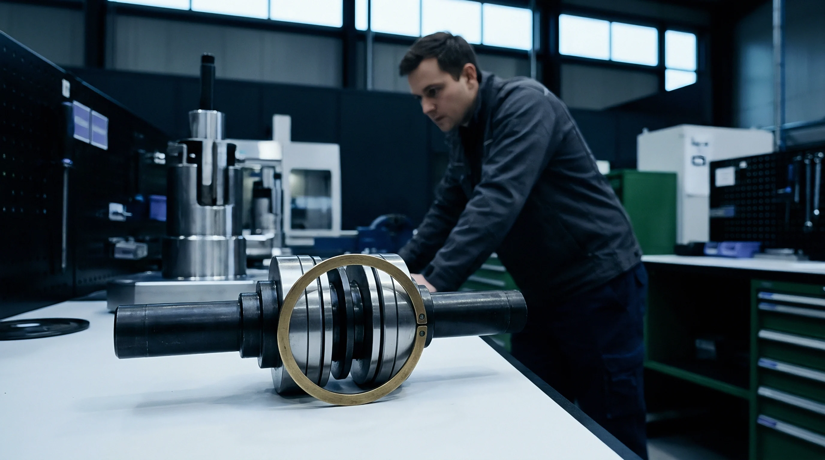

Friction

Thermal Saturation Curves across Continuous Cutting Shifts
Workpiece dimensions begin to wander long before tool wear registers on an edge detector. In a typical horizontal machining cell cutting ductile iron castings under a three-shift production plan, structural cast-iron machine columns absorb heat from spindle bearings, ball nuts, internal motor windings, and hydraulic circuits throughout the first five hours of engagement. During continuous roughing cycles, a 40-taper or 50-taper spindle operating between 6,000 and 12,000 revolutions per minute transfers thermal energy directly across the face-and-taper contact plane into the spindle carrier housing.
The resulting growth is predictable in its physics yet misdiagnosed in daily quality control audits. Linear thermal expansion follows the governing relationship where total axial growth equals the original material length multiplied by the specific thermal expansion coefficient and the mean bulk temperature rise. Structural machine cast iron exhibits a thermal expansion coefficient between 10.5 and 11.5 micrometres per metre per degree Celsius.
A machine column height of 1,200 millimetres undergoing a sustained bulk temperature increase of 4.2 degrees Celsius during seven hours of roughing expands axially by 55 to 58 micrometres. Parts cut at seven in the morning pass bore-depth inspections; parts cut at two in the afternoon display undersized shoulders, misaligned true positions, and inconsistent runout profiles.
Thermal expansion across structural casting accounts for over fifty percent of total workpiece dimensional variance prior to tool wear onset.
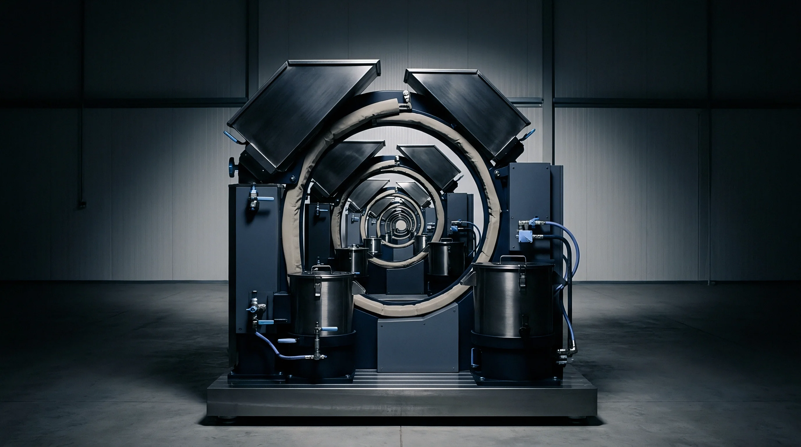
Elastohydrodynamic Film Collapse and Viscous Shearing Dynamics
Viscous heating within recirculating linear guideways and ball screw drives generates secondary heat zones that counteract linear axis compensation routines. Machine axis guideways depend upon continuous fluid film separation governed by elastohydrodynamic lubrication mechanics. As carriages cycle continuously across strokes exceeding 600 millimetres at traverse speeds of 24 to 36 metres per minute, the shearing of fluid lubricants introduces local frictional heat directly into the raceway steel.
The ISO VG 68 slideway oil or NLGI Grade 2 lithium-complex grease experiences continuous internal fluid shear.
The viscosity of an ISO VG 68 mineral lubricant drops from roughly 68 centistokes at 40 degrees Celsius to below 22 centistokes at 70 degrees Celsius. As bulk operating temperatures rise within packed bearing cassettes, this severe thinning compromises film thickness. The dynamic oil film collapses from a nominal 0.8 micrometres down to sub-micron boundary lubrication zones below 0.15 micrometres, triggering metal-to-metal micro-asperity contact.
The friction coefficient jumps from a fluid hydrodynamic value of 0.005 to an unlubricated boundary contact regime exceeding 0.08, generating localized thermal spikes that distort linear scale mounting rails and induce pitching errors across table travels.
Thermal stability requires balancing steady-state heat generation against convective and conductive dissipation paths. The primary operational question is whether variable replenishment intervals stabilize or aggravate structural temperature profiles across prolonged machining operations.

Distortion
Coupled Viscoelastic Behavior and Heat Partition
Machine tool structural elements absorb and shed heat at drastically disparate rates depending on cross-sectional thickness, localized structural mass, and internal coolant contact. Axis drive motors generate stator losses between 150 and 450 watts under continuous duty, while high-pressure internal coolant pumps add fluid-borne thermal energy directly to the cutting zone at rates up to 2.5 kilowatts. When these internal thermal sources interact with cyclical lubrication pulses, the structural machine casting undergoes non-linear volumetric warping rather than uniform linear growth.
Structural thermal distortion breaks down into distinct directional vectors across three physical axes. Structural analysis reveals that thermal gradients create angular tilt errors that multiply along the structural reach of the machine tool, converting fractional millimetre column bends into severe tool-tip positional offsets.
| Component Source | Operating Temperature Rise | Expansion Rate Range | Uncompensated Error at Tool Tip | Thermal Time Constant |
|---|---|---|---|---|
| Spindle Cartridge Bearings | 8.5 to 14.0 °C | 10.8 µm/m/°C | 22 to 38 µm axial | 45 to 75 minutes |
| Z-Axis Ball Screw Drive | 6.0 to 11.5 °C | 11.7 µm/m/°C | 18 to 32 µm linear | 20 to 35 minutes |
| Main Column Casting | 3.0 to 6.5 °C | 11.0 µm/m/°C | 15 to 40 µm angular Abbe | 180 to 320 minutes |
| Axis Guideway Carriages | 4.5 to 9.0 °C | 11.5 µm/m/°C | 8 to 16 µm pitch/yaw | 30 to 60 minutes |
Thermal time constants dictate how rapidly each mechanical element tracks operational shifts. Spindle cartridges reach thermal saturation within roughly one hour of continuous cutting, whereas heavy structural beds require more than five hours to stabilize. This timing mismatch ensures that during standard eight-hour or twelve-hour shifts, the physical geometry of the cutting volume experiences perpetual transient tilting.
The tool center point drifts continuously relative to the primary coordinate datum, rendering static coordinate offsets obsolete within ninety minutes of production startup.
Plant operators frequently compound this condition through poorly timed lubrication cycles that introduce sudden thermal disturbances into stabilized components.
Pumping
Variable Metering Impacts on Thermal Equilibrium
Automated lubrication systems inject hydraulic oils or semi-fluid greases into guide ways and drive screws using fixed timer controls or cycle-dependent pulse controllers. Traditional progressive distributor blocks and single-line resistance injectors deliver discrete metered volumes at set intervals. When an injector fires, it introduces a charge of relatively cool lubricant, typically between 18 and 24 degrees Celsius ambient shop temperature, directly into bearing tracks running at 45 to 60 degrees Celsius.
This localized fluid injection generates immediate thermal shock and fluid displacement. The newly introduced high-viscosity fluid increases mechanical drag within the bearing cassette, raising viscous drag torque by 30 to 80 percent for three to twelve minutes following the replenishment event. Spindle drive motors and axis servo drives draw increased current to overcome this transient viscous resistance, dissipating additional electrical losses as localized heat.
Injecting cold lubricant into high-speed recirculating elements induces instantaneous viscous drag spikes that temporarily accelerate local heat generation.

Volumetric Replenishment Schedules Compared
Production facilities divide sharply over grease versus oil-air lubrication strategies for heavy-duty production machinery. High-pressure grease systems supply intermittent, dense lubricating volumes that seal out swarf but trap internal frictional heat. Progressive automated oil-air delivery provides micro-dosing lubrication alongside a continuous compressed air stream that purges bearing cavities and provides direct convective heat extraction.
- Fixed-Time Cyclic Greasing delivers high lubricant volume at wide intervals, creating severe cycling between boundary friction and extreme viscous shearing that guarantees dimensional oscillation.
- Axis Travel Distance Metering matches fluid delivery directly to mechanical work performed, eliminating over-lubrication during dwell times while failing to account for external thermal saturation.
- Micro-Dosing Continuous Air-Oil Mist supplies steady fractional microlitre quantities per cycle, maintaining structural thermal equilibrium across high-speed axis components while demanding high initial capital investment.
The consequence of unmanaged periodic lubricant injection appears on coordinate measuring machine inspection logs as an erratic saw-tooth dimensional drift curve that defies simple linear regression models.

Tracking
Which Sensor Modality Isolates Thermal Displacement?
Accurate process monitoring requires isolating real machine tool thermal growth from cutting force deflections and tool wear degradation. Facilities frequently rely on ambient temperature sensors positioned outside the machine enclosure, a practice that fails completely because the machine envelope develops an isolated microclimate driven by cutting fluids, hot metal chips, and motor casings.
Effective thermal tracking demands multi-point physical instrumentation across critical heat-flow junctions. Resistance temperature detectors and fiber-optic Bragg grating sensors embedded inside spindle housings, linear drive thrust bearings, and machine casting structural ribs map internal temperature distributions in real time. Fiber-optic lines eliminate electrical noise interference generated by variable frequency drives and high-power servo motors.
| Sensor Technology | Measurement Accuracy | Response Latency | Mounting Criticality | Capital Cost per Axis |
|---|---|---|---|---|
| Surface RTD Platinum PT100 | ±0.05 °C | 1.5 to 4.0 seconds | Requires thermal bonding compound | $120 to $250 |
| Spindle Shaft Eddy Current Probes | ±0.25 µm | < 0.01 seconds | Direct non-contact target targeting | $1,800 to $3,200 |
| FBG Optical Sensor Arrays | ±0.10 °C | < 0.10 seconds | Internal structural embedding required | $2,400 to $5,000 |
| Linear Optical Glass Scales | ±0.50 µm/m | Continuous | Enclosed purge air installation | $1,200 to $2,800 |
Linear scales provide absolute position feedback along axis travels, yet standard scale expansion characteristics introduce their own measurement errors if scale temperatures diverge from the machine bed. Scales mounted with thermal expansion points pinned to the cast-iron frame expand at roughly 8 micrometres per metre per degree Celsius if manufactured from glass, or 10.5 micrometres per metre per degree Celsius if constructed from steel tape matched to machine casting properties. Glass scales with distinct expansion rates report erroneous coordinates when shop ambient conditions shift during long shifts.
Scale temperature matching clauses in machine tool procurement agreements protect buyers against unexpected axis calibration failures.
A rigorous inspection sequence isolates axis positioning drift from ambient facility fluctuations:
- Spindle Cartridge Baseline Probe records tool-holder reference bore runout and length at zero-hour cold condition prior to axis motion.
- Sequential Axis Laser Interferometry quantifies pitch, yaw, and linear positioning accuracy across full travel limits at hourly intervals under dry cycle testing.
- Internal Sump Thermocouple Array monitors cutting fluid delivery temperature variations against ambient machine envelope conditions to detect fluid-borne thermal loads.
- Automated Tool Setter In-Process Verification captures tool-tip Z-axis growth dynamically every twelve minutes during active part production cycles.
The diagnostic records generated through these routines confirm that unmitigated thermal displacement exhibits distinct phases throughout a typical 24-hour manufacturing shift.


Drift
Worked Engineering Construction of Tool Tip Growth
To quantify the combined error envelope, construct a representative precision horizontal milling center performing continuous milling operations on steel housings across a twelve-hour operating window. The mechanical setup incorporates a cast iron column with an effective structural height of 950 millimetres, a ball screw of 800 millimetres travel, and a dual-contact taper spindle running at a continuous mean speed of 8,500 revolutions per minute.
The manufacturing process runs under a pulsed volumetric lubrication schedule supplying 1.5 cubic centimetres of ISO VG 68 slideway oil every 45 minutes to linear guides, alongside continuous refrigerated through-spindle coolant maintained at 20 degrees Celsius. However, machine structural columns experience no active refrigeration, absorbing ambient air variations and conduction losses from axis drive motors.
Assume an ambient air temperature increase from 19 degrees Celsius at 06:00 to 26 degrees Celsius at 14:00, combined with internal motor heat dissipation yielding a local column temperature increase of 5.8 degrees Celsius over initial baseline. The linear expansion of the structural column along the vertical Y-axis calculates directly from material properties:
Column growth equals 950 millimetres multiplied by 11.0 multiplied by 10 to the power of negative six per degree Celsius, multiplied by 5.8 degrees Celsius. This evaluates to 0.0606 millimetres, or 60.6 micrometres of vertical deflection. Concurrently, the Z-axis ball screw experiences continuous cycling, raising its mean shaft temperature by 7.2 degrees Celsius despite end-bearing pretensioning.
For an 800 millimetre screw fixed at one end and supported at the other with pre-stretched bearings, residual unconstrained thermal expansion produces 26.9 micrometres of axial positional error across the stroke.
When the automated lubrication injector discharges at 45-minute intervals, instantaneous viscous shearing raises the carriage saddle temperature by an additional 1.8 degrees Celsius for eight minutes following the cycle. This creates a localized pitch angular error of 14 microradians. Projected over a spindle gage length of 280 millimetres from the gage line to the cutting tip, this angular deflection adds an extra 3.9 micrometres of lateral tool displacement.
Summing these orthogonal and angular vectors yields a maximum spatial tool-center-point drift of 66.8 micrometres along the Y-Z plane. Where drawing specifications mandate a total bore location tolerance of 25 micrometres, the process produces scrap parts within four hours of startup unless dynamic mitigation intervenes. The line operator watching these dimensional failures often replaces carbide inserts under the mistaken assumption that physical tool wear drives the error.

Compensation
Real-Time Algorithmic and Structural Offsets
Mitigating continuous thermal drift requires integrating real-time mathematical compensation models directly into the computerized numerical control kernel. Modern open-architecture machine controllers accept external sensor inputs to apply coordinate shifts dynamically across axis drive registers. These systems process empirical thermal transfer functions that correlate real-time temperature sensor telemetry with measured spatial deformation patterns.
Multiple regression models and artificial neural networks calculate dynamic offset vectors applied directly to the machine coordinate system. The controller injects minute micro-step offsets into axis command loops at rates exceeding 500 Hertz, shifting the active machine origin to cancel out physical thermal expansion. When the spindle housing expands axially by 12 micrometres, the controller subtracts 12 micrometres from the active Z-axis work coordinate offset automatically.
External hardware systems reinforce these software compensations by eliminating thermal gradients at their mechanical origins. Controlled-temperature spindle chillers circulate refrigeration fluid through helical passages machined directly into spindle carrier castings. These chillers regulate coolant temperature within 0.1 degrees Celsius of the machine base temperature, preventing heat transfer into structural castings.
Concurrently, axis ball screws employ hollow-core cooling designs where refrigerated fluid circulates continuously through the center of the rotating shaft. This extracts internal frictional heat generated by ball nut friction, holding screw expansion below 3 micrometres over twelve hours of continuous rapid traverse motion.
Machine alignment contracts specifying ISO 230 part 3 thermal performance tests force machine tool builders to guarantee spatial stability under active cutting loads.
Failing to implement synchronized algorithmic compensation and closed-loop thermal stabilization leads directly to severe tolerance stack-up, escalating scrap rates, and premature equipment wear across multi-shift production operations.
Governance
Operating Procedures for Multi-Shift Scale Readiness
Engineering controls fail when machine maintenance routines operate in isolation from production scheduling and quality monitoring. Long-shift dimensional control requires standardized operating rules governing warm-up sequences, lubricant replenishment timing, and tool offset updates across shifts. Transitioning between day and night shifts introduces severe ambient temperature swings that destabilize unmanaged machine tools.
Plant management maintains strict operating limits across all precision machining cells:
- Pre-Shift Thermal Stabilization Routines mandate executing a thirty-minute kinematic warm-up macro that cycles axes and rotates spindles at operating speeds prior to qualifying first-piece geometry.
- Synchronized Micro-Lubrication Windows restrict heavy axis lubrication events to non-critical cutting operations or automated pallet exchange cycles, eliminating transient viscous heating during finishing passes.
- Periodic Artifact Probing Inspections automate in-cycle measurement of calibrated ring gages mounted on the machine fixture table to track thermal drift every ninety minutes.
- Workpiece Temperature Normalization Controls require thermal soaking of rough raw castings within the controlled facility environment for twenty-four hours before loading them onto machine fixtures.
When operational teams enforce these boundaries, dimensional capability metrics achieve stability across continuous high-volume runs. Without such structural discipline, machine operators continually adjust tool wear offsets to chase thermal drift, hiding mechanical failures under arbitrary program modifications.
Equipment suppliers frequently claim their internal thermal software models eliminate all dimensional drift automatically. The true limit of machine performance under continuous thermal loading rests on whether the buyer verifies thermal stability through physical artifact testing under full cut conditions before accepting factory delivery.