Kinematic Fixture Principles for Thin Wall Injection Molded Metrology
Kinematic fixtures isolate thin-wall injection moldings on six non-redundant locators to eliminate probe-induced flexure and false dimensional rejections.


Contact
Coordinate measuring machines record false dimensional rejections when thin thermoplastic moldings deform under touch-trigger stylus engagement. A 1.0 millimeter injection molded polypropylene instrument bezel deflects upward of 60 micrometers when struck by a standard 0.075 Newton ruby probe. Tactile triggers displace flexible plastic.
That displacement consumes forty percent of a typical 0.150 millimeter profile tolerance before geometry calculations begin. Metrology technicians routinely interpret these readings as tool sink or differential shrinkage, triggering unnecessary steel recuts in production molds.
Kinematic location restricts six degrees of rigid body motion through six distinct, non-redundant interface constraints. Traditional machining jigs use planar nests, full-perimeter vices, or toggle clamps to restrain raw stock against cutting loads. Thin-wall molded components lack the structural rigidity to resist these clamping forces without severe strain distortion.
When a warped molding is pressed flat against an over-constrained aluminum nest, internal stresses redistribute throughout the shell. The measuring routine captures the shape of the fixture instead of the geometry delivered by the injection press.
Exact Constraint Mechanics on Flexible Thermoplastics
Kinematic design balances spatial degrees of freedom through three orthogonal reference planes. A primary plane arrests three degrees of freedom: pitch, roll, and translation along the normal axis. Two spherical interfaces establish a secondary reference line, removing yaw and lateral translation.
A final point contact arrests the remaining sliding degree of freedom along the longitudinal axis. Six constraints lock six degrees. Each interface transmits force strictly normal to the contacting surface without generating bending moments or tangential friction locks.
Kelvin couplings employ three spherical balls mating into a concave trihedral socket, a vee-groove, and a flat plate. Maxwell arrangements distribute three spherical studs into three vee-grooves oriented at 120 degrees toward a common center. For thin-walled polymer enclosures, Kelvin geometry concentrates excessive mechanical shear into the trihedral pocket.
Maxwell configurations distribute locating friction symmetrically, allowing the component to slide into equilibrium under controlled gravity seating.
| Polymer Matrix | Wall Nominal (mm) | Flexural Modulus (MPa) | Trigger Force (N) | Induced Deflection (um) | Tolerance Budget Lost (%) |
|---|---|---|---|---|---|
| Unfilled Polypropylene | 0.80 | 1300 | 0.10 | 74.2 | 49.5 |
| Unfilled Polypropylene | 1.20 | 1300 | 0.10 | 22.0 | 14.7 |
| Polycarbonate / ABS Blend | 0.80 | 2400 | 0.10 | 40.2 | 26.8 |
| Polycarbonate / ABS Blend | 1.20 | 2400 | 0.10 | 11.9 | 7.9 |
| 30% Glass Filled PA66 | 0.80 | 8500 | 0.10 | 11.3 | 7.5 |
| 30% Glass Filled PA66 | 1.20 | 8500 | 0.10 | 3.4 | 2.3 |

Tactile Probe Pressure and Local Surface Bending
Stylus velocity influences peak impact load prior to trigger circuit disruption. Modern kinematic touch-trigger probes decelerate upon contact, yet mechanical inertia generates transient dynamic forces that exceed static trigger thresholds by three hundred percent. A stylus traveling at 8 millimeters per second against an unsupported thin rib introduces local plate flexure that mimics tool draft deviations.
Raw parts sag between pins. Coordinate measuring software registers the point after displacement has occurred, recording an artificially thin wall or an out-of-square flank.
Scanning styli exacerbate localized deflection through continuous drag force along the measurement trajectory. A 2-millimeter diameter diamond-coated sphere dragged across unfilled polybutylene terephthalate produces dynamic frictional drag, generating lateral moments that tilt high-aspect locating ribs. Technicians attempting to verify datum locations induce pitch errors up to 0.08 degrees purely through probe friction.
Toolmakers often counter that molded parts inevitably distort during physical evaluation and that drawing tolerances should expand accordingly.

Nest
Support structures manufactured from monolithic aluminum billets frequently cause repeatability drift when used for flexible part metrology. Technicians mill negative cavity contours matching CAD surfaces, expecting continuous surface support to stabilize delicate wall sections. Injection molded resins experience differential shrinkage across flow paths and cooling channels.
When a production molding sits inside a line-to-line contoured cavity, high points touch prematurely while adjacent regions hover over voids. Clamping forces create false rejections.
Kinematic fixtures replace full-form cavity tooling with discrete, micro-adjustable spherical locators positioned directly beneath functional datum targets. These locators concentrate known reaction vectors at structural junctions, such as sidewall-to-base intersections or internal boss roots, where section thickness provides elevated area moments of inertia. Positioning support pins away from thin unsupported panels eliminates the drumhead deflection observed during tactile probing.
Spherical Point Location and Hertzian Stress Limits
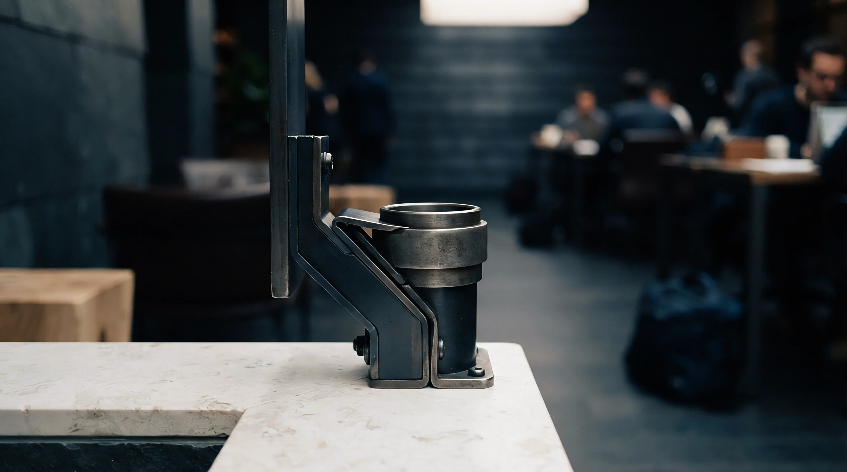
Hardened stainless steel spheres contacting soft polymer shells produce high localized contact stresses. A 6-millimeter diameter spherical locator supporting an unfilled polyamide component under a 5-Newton hold-down force generates compressive stresses exceeding 32 megapascals. Thin plastic sections yield under pressure.
When localized stresses exceed the yield point of the polymer matrix, spherical tips leave permanent indents, shifting the vertical coordinate reference datum downward across successive measurement runs.
Tungsten carbide balls paired with matching radiused resin pads mitigate surface yield while preserving kinematic determinism. Increasing the contact radius from 3 millimeters to 12 millimeters expands the Hertzian contact area by four hundred percent, reducing peak compressive pressure below viscoelastic flow thresholds. Silicon nitride ceramic spheres provide low friction coefficients against engineering plastics, eliminating stick-slip behavior during thermal expansion cycles inside the measuring cell.
A kinematic locator supports the component without fighting internal molding stresses.
Operator Torque Variance on Manual Overclamps
Hand-operated toggle clamps represent the largest source of measurement variability in receiving inspection departments. Quality technicians apply disparate closing forces to manual clamps, varying clamp pad loads from 15 Newtons to over 90 Newtons on the same locating station. This variance bends perimeter flanges, twists mounting tabs, and induces artificial flatness failures across opposite part corners.
Tool wear alters locator positions.
Air cylinders with regulated pneumatic proportional valves maintain holding forces within 0.05 Newtons of design targets across all production shifts. Solenoid valves sequence actuation timing, seating primary datums prior to closing secondary or tertiary retaining fingers. Controlled pneumatics prevent the elastic buckling that occurs when aggressive manual clamps pin warped components against rigid stops.
- Hertzian Surface Brinelling occurs when small-radius locating pins permanently indent soft thermoplastic datums under excessive hold-down loads.
- Parasitic Moment Generation develops when spherical locators fail to pivot freely during secondary clamp actuation, inducing torsional strain through the part spine.
- Thermal Centerline Drift manifests when aluminum fixture plates expand at three times the rate of low-shrinkage filled polymers during uncontrolled room temperature swings.
- Friction Lock Warpage traps transient assembly stresses at contact pads, preventing the molding from reaching mechanical equilibrium before scanning begins.
Ignoring localized contact stresses causes automated metrology routines to accept distorted moldings that bind during final vehicle assembly, generating extensive line stoppages and expensive scrap campaigns.
Compliance
Engineering drawings specify non-rigid plastic components under two distinct states according to international geometric dimensioning standards. Free state conditions represent parts resting unsupported, where dimensional variations incorporate unconstrained molding warpage, post-mold crystallization, and gravity sag. Restrained conditions mandate that specific datum targets receive designated clamping forces before feature tolerances apply.
Part stiffness drops sharply here.
Misunderstandings between design engineers and metrology laboratories frequently center on restrained drawing notes. When a print calls out a restrained datum frame without specifying clamp locations, force vectors, and tightening sequences, metrology staff construct over-constrained holding jigs. These fixtures force warped features into nominal alignment by applying dozens of non-standard grip points.
Coordinate measuring cycles create plant bottlenecks.

Which Datum Features Govern Part Repeatability?
Primary datum selection dictates whether a flexible molding can locate repeatably on a coordinate stage. Designers frequently choose large decorative Class-A cosmetic surfaces as primary datums because these surfaces interface directly with end customers. Exterior thin shells possess the lowest torsional stiffness across the entire part envelope.
Friction locks unstable molding stresses. Clamping a non-planar 1.2 millimeter exterior skin against fixed locators twists underlying structural ribs out of position.
Rigid internal attachment bosses or reinforced perimeter sealing tracks serve as superior primary datums. Three locating points positioned at the stiffest structural ribs define a stable primary plane that tolerates manufacturing variations without transmitting bending moments into aesthetic panels. Secondary and tertiary pin locations pick up molded holes cored directly by the stationary mold half, avoiding split-line mismatch errors inherent to moving slides.
Specifying ASME Y14.5 restrained conditions without an explicit clamping torque specification voids vendor correlation data during dispute arbitration.
| Measurement Metric | Free State Optical | Contoured Nest Manual Clamp | 6-Point Kinematic Pneumatic |
|---|---|---|---|
| Primary Datum Z Repeatability (um) | 84.5 | 38.2 | 4.1 |
| Mounting Hole True Position (mm) | 0.48 | 0.22 | 0.08 |
| Perimeter Profile Band (mm) | 1.25 | 0.35 | 0.42 |
| Gage R&R Part-to-Tolerance (%) | 42.8 | 29.4 | 7.6 |
| Inspection Cycle Time (seconds) | 240 | 180 | 45 |
Free State Warpage versus Restrained Drawing Modifiers
Standard ISO 10579 governs non-rigid workpieces, outlining requirements for indicating restrained conditions on engineering definitions. The standard permits drawing notes that define maximum allowable restraining forces applied at specified target locations. When molders release parts using unrestrained optical scans while assembly plants inspect using high-force pneumatic holding jigs, quality audits report complete correlation divergence.
Three locators establish the primary plane.
Finite element simulations of the mold filling and cooling stages predict residual stress fields and resulting free-state distortions. Metrology engineers import predicted warpage vectors directly into fixture design software to calculate the exact clamping forces needed to seat datum points without distorting adjacent geometry. Clamping force targets should never exceed the force exerted by mating fasteners in the final product assembly.
- Identify Primary Structural Nodes by calculating local moment of inertia maps across the molded component CAD model.
- Isolate Injection Tooling Parting Lines to ensure locating pads sit entirely within features formed by the stationary mold half.
- Define Hertzian Contact Maximums based on ambient room temperature compressive yield strengths of the chosen thermoplastic compound.
- Simulate Pneumatic Clamping Sequences in nonlinear structural analysis software to verify that hold-down actions induce zero parasitic bending in secondary datums.
- Establish Correlation Offsets comparing unrestrained baseline optical scans against kinematically supported point clouds before final fixture sign-off.
A fixture designer aligns clamp vectors directly opposing locator pins to cancel all primary bending moments.

Calibration
Statistical validation of flexible part metrology requires rigorous Gage Repeatability and Reproducibility studies under standard production conditions. Automotive and medical standards mandate that measurement system variability consume less than ten percent of total product tolerance bandwidth. Standard modular fixtures built from aluminum extrusion profiles rarely achieve this threshold on thin plastic components.
Steel frames expand under shop warmth.
Modular fixture components shift under dynamic measuring loads. T-slot nuts slide microscopically within extruded channels when struck by heavy tactile styli or bumped during operator loading. Bolted joints lack the shear rigidity provided by pinned, monolithic kinematic mounts.
Gage repeatability studies fail repeatedly. Fixtures showing acceptable repeatability during static gauge block testing frequently fail when cycling lightweight polypropylene components through multi-operator studies.

What Clamping Forces Induce Measurable Deflection?
Nonlinear deflection curves characterize thin thermoplastic sheets subjected to point loading. An empirical test applying variable normal loads against a 1.0 millimeter polycarbonate plate demonstrates that vertical deflection accelerates rapidly between 0.05 and 0.50 Newtons before reaching membrane tension stabilization. Mold shrinkage compounds thermal displacement.
Low clamping loads fail to seat the part against datum locators, while high clamping loads deform the shell.
Pneumatic actuators equipped with micro-regulators deliver consistent hold-down loads within an optimal operating window of 0.8 to 1.4 Newtons. This narrow envelope overcomes minor molding flash and warpage resistance while avoiding structural membrane strain. Metrology engineers determine the precise envelope by monitoring surface deflection with non-contact spectral confocal sensors while incrementing pneumatic pressure.
Tactile probing forces exceeding 0.08 Newtons induce more than 35 micrometers of localized bending on unsupported 1.0 millimeter polypropylene walls.
| Fixture Topology | Gage R&R (% Tolerance) | Tactile Cycle Time (s) | Optical Cycle Time (s) | Fixture Tooling Cost (USD) |
|---|---|---|---|---|
| Manual Contoured Resin Nest | 31.4 | 720 | 310 | 6,500 |
| Modular Extruded T-Slot Frame | 24.8 | 650 | 280 | 4,200 |
| Kinematic 6-Point Pneumatic Base | 6.8 | 410 | 85 | 14,500 |
| Over-Constrained Vacuum Chuck | 38.2 | 580 | 190 | 18,000 |
Optical Rotary Scanning Headroom against Coordinate Machines
Tactile coordinate machines represent an operational bottleneck in modern injection molding facilities. Measuring an intricate front bumper fascia or medical fluid manifold using tactile styli takes upwards of fifteen minutes per piece. The machine must slow its approach speeds to minimize dynamic probe impact forces against delicate wall sections.
Optical metrology eliminates physical touch error.
Structured light scanners mounted on high-speed collaborative robotic arms digitize complex thin-wall parts in less than ninety seconds. Kinematic fixtures for optical scanning use minimalist carbon-fiber spars and micro-point locators to maximize visible surface area, eliminating the optical occlusion caused by massive aluminum clamp towers. High inspection throughput allows molders to perform statistical process control across consecutive press cycles rather than relying on delayed lot sampling.
- Thermal Drift Audit Records confirming fixture base stability across an ambient shop range of 18 to 28 degrees Celsius.
- Datum Target Contact Footprints verifying zero interference with nominal tool parting lines, ejector pin marks, or gate vestige locations.
- Dynamic Load Deflection Reports proving less than 2 micrometers of locator displacement under maximum pneumatic hold-down sequencing.
- Optical Clearance Sightline Studies documenting unhindered scanner line-of-sight across ninety-five percent of designated inspection features.
Under ISO 17025 accreditation rules, calibration certificates must identify whether reported measurement uncertainties incorporate component deflection generated by fixturing loads, invalidating correlation reports where fixture flexure remains unquantified.


Settlement
Commercial disputes between Tier 1 injection molders and automotive OEMs routinely trace back to mismatched metrology fixturing strategies. A supplier certifies component compliance on a kinematic optical holding jig at their molding plant, while the assembly facility rejects the incoming lot using an over-constrained manual clamping nest. The supplier produces dimensional verification reports showing process capability values exceeding 1.67, yet the customer cannot assemble the components without violent manual forcing.
Both parties present certified metrology dossiers describing the same physical parts.
Resolving these disputes requires contracting explicit kinematic locating architectures inside the master tooling agreement before cut steel milestones occur. Tooling agreements must define not merely the coordinate locations of datum targets, but the exact spherical radii of contact points, the holding load vectors, and whether inspection routines apply free state or restrained condition modifiers. Aligning the physical measurement boundary conditions eliminates the phantom quality deviations that stall production releases.
Fixture components machined from dissimilar metals alter reference coordinates through routine daily temperature swings.

Thermal Expansion Mismatch across Tooling Materials
Temperature fluctuations across measuring laboratories introduce insidious dimensional drift between fixture frames and molded resin components. Aluminum 6061-T6 exhibits a coefficient of thermal expansion of approximately 23 micrometers per meter per Kelvin. Unfilled semi-crystalline polyolefins exhibit thermal expansion coefficients exceeding 120 micrometers per meter per Kelvin, roughly five times greater than the metal holding frame.
A five-degree temperature shift inside a quality laboratory alters part dimensions by 0.3 millimeters across a 500-millimeter instrument panel.
Invar alloys and carbon-fiber composite plates exhibit near-zero coefficients of thermal expansion, providing exceptional mechanical stability for high-precision metrology frames. When a warm molding fresh from the injection press is clamped onto an Invar base, the part contracts as it cools to ambient room conditions. Kinematic spherical joints with polished diamond-like coatings permit the shrinking molding to slide smoothly across locator tips toward its thermal center without buckling or binding.

Production Release Gates for Multi Cavity Tooling
Scaling production from a single-cavity prototype mold to an eight-cavity production tool strains metrology lab capacity. Measuring eight distinct parts per press cycle creates immediate inspection queues at coordinate measuring stations. When quality engineers construct eight individual fixturing nests, manufacturing variations between nests introduce false cavity-to-cavity variance.
Toolmakers waste weeks adjusting individual mold cavity dimensions when the observed variance originates entirely within manual toggle clamp disparities across the eight fixture stations.
A single master kinematic fixture base equipped with swappable, serialized locating modules eliminates cross-station fixturing noise. Each locating module features high-precision dowel locations, ensuring repeatability within 2 micrometers of the master coordinate frame. Standardizing the locator interface isolates genuine mold cavity discrepancies, such as flow imbalance or cooling channel variance, allowing process engineers to tune injection parameters with high confidence.
How the industry will standardize kinematic boundary conditions for thin-wall additive manufacturing components exhibiting anisotropic viscoelastic relaxation across multi-day storage windows remains an open dispute among industrial metrologists.