Differential Elevation Mapping under Dynamic Axle Loads in Distribution Facilities
Dynamic axle loads cause localized elastic slab deflection and subgrade pumping that static laser surveys miss, demanding mobile dynamic profilometry before automation deployment.
Wheel
Dynamic Load Transfer and Floor Deflection
Rolling loads from heavy automated guided vehicles induce localized elastic depressions far deeper than static surveys indicate. Because conventional static floor leveling measurements miss structural movement beneath running gear, a six-tonne dual-axle vehicle traveling at four meters per second across a two-hundred-millimeter unreinforced concrete slab creates a transient deformation basin that moves continuously with the contact point. Elastic slab deflection under these dynamic conditions reaches two point eight millimeters.
The scale of this transient dip depends directly on concrete flexural modulus, subgrade reaction modulus, vehicle velocity, and tyre footprint dynamics.
Chassis height sensors on narrow-aisle automated vehicles often misinterpret localized slab flexing as floor unlevelness. Drive control electronics then adjust suspension damping or apply steering corrections to counter perceived tilt, setting off mechanical oscillations along straight travel lanes. Millions of these transient loading cycles degrade the bond between the concrete slab base and the crushed aggregate subgrade, creating air gaps directly underneath heavily traveled wheel lines that accelerate long-term slab settlement and structural joint failure.
Elastic slab deflection under a six-tonne axle load moving at four meters per second reaches two point eight millimeters on a two-hundred-millimeter unreinforced concrete floor.

Contact Pressure and Elastic Basin Geometry
Polyurethane treads generate footprint contact stresses ranging between eight and fifteen megapascals, storing strain energy that releases directly into the slab. These concentrated point loads stress surface concrete caps far beyond uniform spatial averages calculated during initial facility floor design. High contact pressures combined with dynamic wheel impact over slab contraction joints cause micro-fracturing within top aggregate layers.
The deflection basin spreads radially from the tyre contact center. Flexural stress concentrations reach peak intensity at panel corners and free edges where shear transfer mechanisms are absent or degraded. Calculating true differential elevation requires measuring slab deflection profiles under maximum operational wheel loads at maximum vehicle travel velocity rather than relying on unweighted optical surveying techniques.
Ignoring transient elevation dips under moving loads causes automated vehicle navigation guidance locks to disengage and halts warehouse transport loops.

Scan
Continuous Mobile Laser Profiling
High-frequency optical measurement systems capture floor topography along actual vehicle transit routes rather than on static grid nodes. Discrete grid surveys spaced at three-meter intervals omit micro-topographical joint drops that tilt automated masts. Profiling rigs towed at operational vehicle speeds gather elevation readings at millimeter intervals along exact wheel tracks, where wheel path profile directly determines stability.
Continuous optical mapping exposes discrete floor elevation steps, joint faulting, and localized surface wavelength undulations that trigger vehicle mast resonance.
Differential elevation mapping correlates wheel path coordinates with instantaneous laser distance telemetry. Mobile profilometers record two parallel track profiles simultaneously to evaluate roll, pitch, and cross-fall slopes experienced by automated material handling equipment. This localized data reveals surface irregularities that standard overall floor levelness metrics smooth out over large areas.
Data Filtering and Spatial Resampling Algorithms
Raw topographical point clouds contain noise from surface texture, dust, and concrete joint chamfers. Algorithmic filtering separates concrete surface texture from long-wavelength floor undulations and short-wavelength joint faulting. Applying digital Butterworth filters isolates high-frequency surface steps that impact wheel contact while preserving macro-level slope profiles governing overall vehicle lean.
| Survey Method | Sampling Interval | Operational Load | Detection Capability |
|---|---|---|---|
| Optical Total Station Grid | 3000 mm | Zero Load | Macro levelness and slab inclination |
| Digital Straightedge Profiler | 300 mm | Zero Load | Localized waviness and peak-to-trough steps |
| High-Speed Laser Profilometer | 10 mm | Zero Load | Micro-stepping, joint arris faulting, track roll |
| Chassis Telemetry Profiling | 5 mm | Full Operational Load | Live elastic basin deflection and true dynamic elevation |
Resampling spatial elevation datasets into five-millimeter travel intervals allows direct simulation of vehicle chassis kinematics. Engineers feed transformed elevation profiles directly into vehicle dynamic models to predict mast head displacement, wheel load variations, and emergency stop sensor tripping thresholds before deploying autonomous fleets.
Compliance with TR34 Edition 4 Property F3 demands elevation sampling at fifty-millimeter intervals along specified vehicle transit lines to prevent vertical mast displacement.
Whether chassis-mounted optical sensors can reliably isolate transient slab strain from tyre deformation during high-speed braking remains an open empirical question.


Tolerance

What Floor Surface Metrics Govern Automated Guided Vehicles?
Automated guided vehicles operating in narrow aisles rely on floor flatness and levelness standards to prevent mechanical collisions. Standard industrial slab specifications like ACI 117 F-Numbers or TR34 Floor Classes measure general spatial variations across broad facility spaces. Automated material handling vehicles demand strict transverse elevation control between narrow wheel tracks.
A two-millimeter elevation difference across a twelve-hundred-millimeter vehicle track width produces significant lateral sway at top rack storage elevations.
Property F3 under TR34 fourth edition and DIN 15185 establish strict limits for transverse elevation differences and rate-of-change metrics along defined vehicle transit aisles. Consequently, floor specifications require separate evaluation of static elevation variance and dynamic surface deformation, as uncorrected floor dips halt vehicle operations.

Decision Criteria for Path Rework
Evaluation of floor path suitability proceeds through structured threshold criteria before approving vehicle deployment.
- Transverse elevation differential ~ Maximum allowable elevation offset between left and right wheel tracks along defined transit paths cannot exceed one point five millimeters under static or dynamic conditions.
- Step elevation change at joints ~ Vertical offsets across saw-cut contraction joints or construction joints must remain below zero point eight millimeters to avoid high-impact loads on wheel bearings.
- Longitudinal rate of change ~ Continuous elevation slope changes along the direction of travel must not exceed one millimeter per meter to prevent chassis bottoming and sensor blinding.
- Dynamic deflection allowance ~ Maximum transient flexural depression under maximum dynamic axle weight must remain within one point two millimeters to ensure vehicle optical guidance continuity.

Mast Sway Amplification and Sensor Lockout
A minute elevation variance across a vehicle axle translates into significant lateral displacement at the top of a reach truck mast, where mast tilt multiplies optical errors. A narrow-aisle vehicle carrying a twelve-hundred-kilogram pallet to a fourteen-meter storage location experiences thirty-five millimeters of lateral mast movement for every two millimeters of transverse floor elevation step.
| Vehicle Class | Maximum Lift Height | Allowable Transverse Step | Maximum Transverse Slope |
|---|---|---|---|
| Standard Autonomous Mobile Robot | 1.5 m | 2.5 mm | 1.5 percent |
| High-Reach AGV Forklift | 8.5 m | 1.2 mm | 0.5 percent |
| Very Narrow Aisle Turret Truck | 14.0 m | 0.8 mm | 0.2 percent |
| Heavy-Duty Pallet Carrier | 0.5 m | 3.0 mm | 2.0 percent |
Lateral mast deflection alters the line of sight for vehicle safety LiDARs and optical pallet identification scanners. When mast sway pushes onboard sensors out of alignment with rack reflectors, vehicle safety controls initiate emergency stop sequences. Frequent false safety stops reduce facility throughput, stall material flows, and cause accelerated wear on drive motors and braking systems.
Clause 5.3 of DIN 15185 establishes a maximum transverse slope of one millimeter per meter for narrow-aisle storage facilities, forcing floor grinding contractors to rework out-of-spec transit paths.


Pumping
Dynamic Dowel Shear and Void Evolution
Repeated passage of heavy rolling axles over unsealed contraction joints destabilizes subgrade soil layers. When an axle crosses a floor joint, vertical shear force transfers from the approach panel to the leave panel through embedded steel dowel bars or aggregate interlock acting as shear pins. Inadequate dowel cross-section or loose dowel socket embedding allows differential vertical deflection between adjacent slab edges.
Rapid downward deflection of the loaded slab edge forces air and residual sub-slab moisture out through open joint seals at high velocity. As void spaces expand under these dynamic impacts, loss of subgrade moisture compromises long-term slab support. This hydraulic action washes fine soil particles away from the underside of the slab, creating unsupported void pockets directly beneath critical wheel load paths.
Structural Failure Modes under Rolling Traffic
Subgrade erosion alters slab structural mechanics from uniform continuous support to cantilevered beam loading. Slab failure beneath dynamic wheel tracks manifests through specific physical degradation patterns.
- Dowel looseness ~ Repetitive impact loads enlarge dowel sockets within fresh concrete, reducing shear transfer efficiency across adjacent slab panels.
- Corner cracking ~ Unsupported panel corners yield under dynamic axle passes, generating localized structural fracturing along transit lanes.
- Subgrade erosion ~ High-velocity pore water movement beneath deflecting joints washes away fine aggregate particles and creates voids.
- Joint spalling ~ Differential elevation steps cause vehicle wheels to strike exposed joint arris edges, fracturing surface concrete caps.
Panel corners lack two-dimensional continuity, leaving them vulnerable to flexural cracking under repeated dynamic impact. Unsupported slab edges drop downward during axle passage and rebound abruptly as the vehicle rolls onto the next panel. Uncorrected edge deflections lead to progressive slab cracking, surface concrete spalling, and total loss of joint transfer capability.
Unsealed contraction joints under high-frequency wheel traffic accelerate subgrade moisture loss and premature edge spalling.
Joint spalling is frequently attributed to vehicle driver error, but dynamic slab edge deflection remains the primary structural cause.
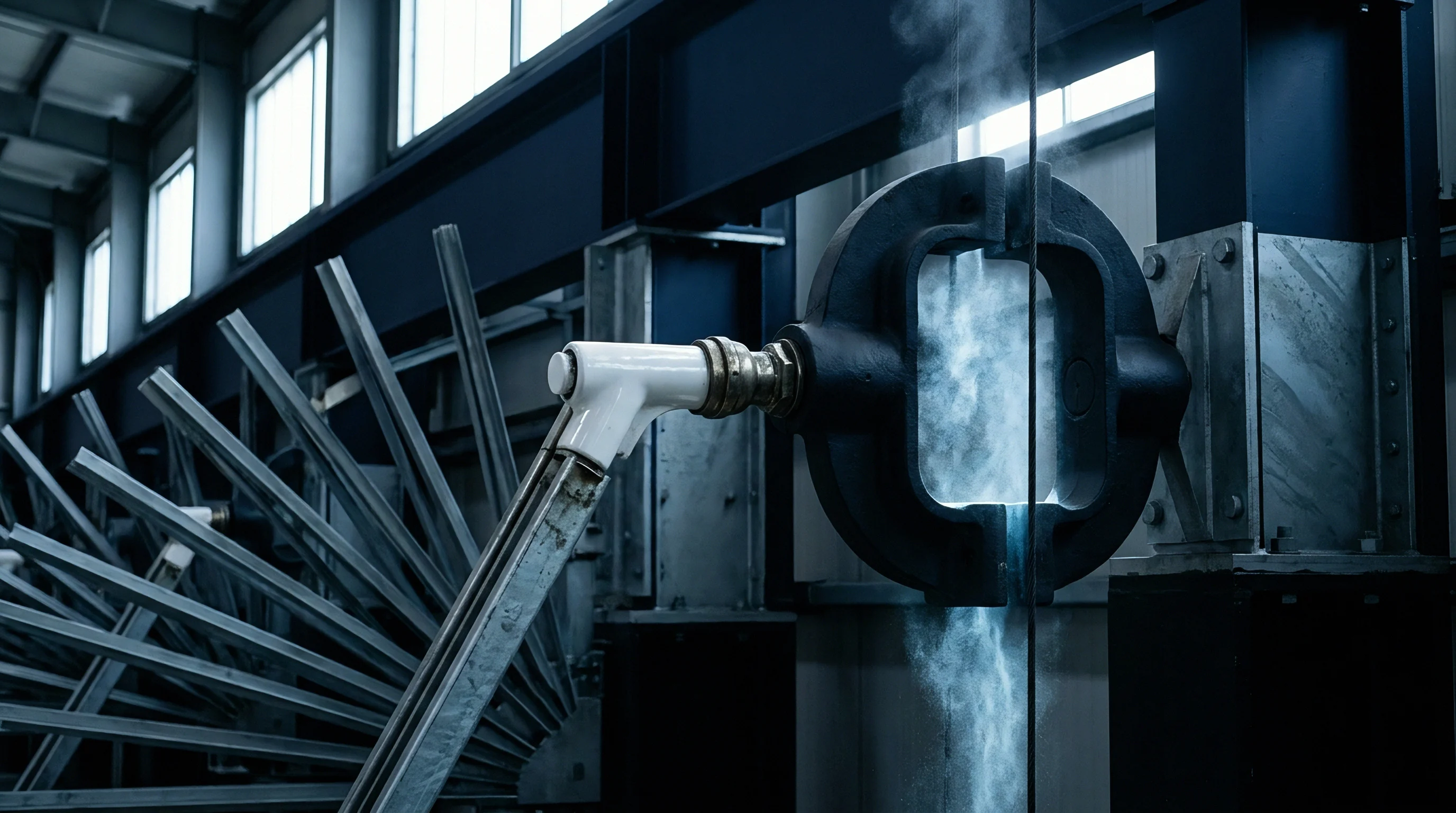

Grout
Sub Slab Resin Injection and Lifting Protocols
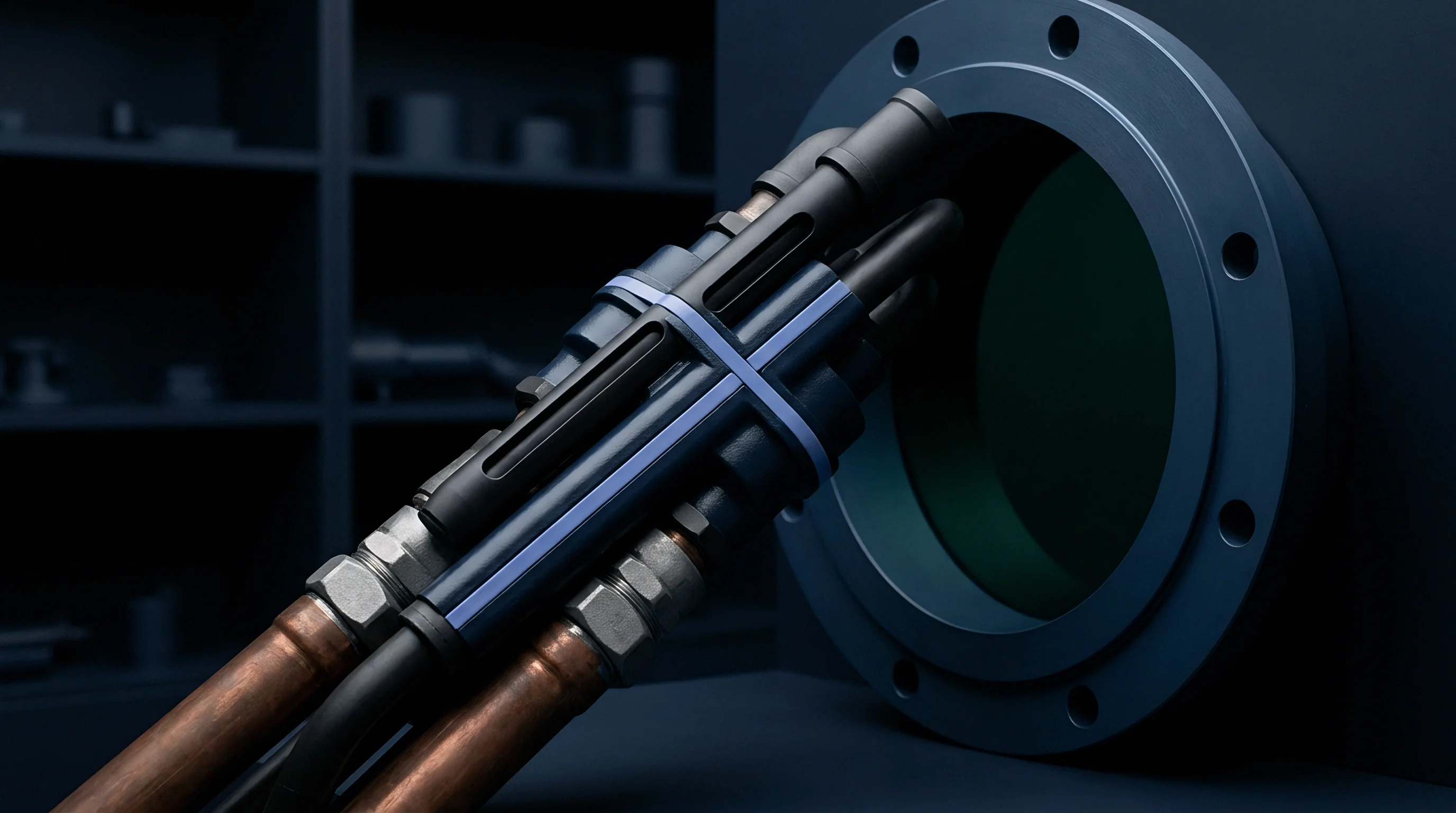
Structural polyurethane resins restore subgrade support by expanding into sub-slab voids under controlled injection pressure. Expanding within seconds, high-density closed-cell polymers penetrate subgrade voids, displace trapped water, and bind loose aggregate together. This expansion forces settled concrete panels upward toward target elevation profiles while establishing continuous vertical support under high-use wheel aisles.
Injection protocols mandate monitoring panel positions with high-precision optical laser levels during chemical injection. Technicians pump liquid polyurethane components through pre-drilled ten-millimeter injection ports aligned along settled joint lines. Rapid expansion forces polymerize within forty-five seconds, delivering up to four hundred kilopascals of lifting pressure to compensate for subgrade loss.

Targeted Grinding versus Slab Stabilization
Surface grinding corrects static high spots but fails to eliminate void spaces beneath unbacked concrete slabs. Because grinding removes sound surface concrete, reworking floor profiles through localized laser-guided grinding reduces concrete cover over top reinforcing mesh, weakening local flexural strength at slab joints.
Consider a two-thousand-five-hundred square meter distribution bay suffering from eighteen settled contraction joints under five-and-a-half-tonne dynamic axle loads. Profile grinding alone costs forty-five dollars per linear meter with three days of facility operational downtime. Grinding reduces slab thickness by six to eight millimeters at joint arris edges, lowering structural shear load capacity by fourteen percent under yield line calculation models.
By contrast, deep polyurethane structural resin injection costs one hundred eighty dollars per injection point with one single day of aisle closure. Polymer injection fills sub-slab voids ranging from twelve to thirty-five millimeters deep, restoring slab load transfer efficiency from forty-two percent back to eighty-eight percent. Combining sub-slab resin injection with light surface profile grinding delivers permanent structural stability without sacrificing concrete slab thickness.
- Deploy optical laser level receivers along target slab panel perimeters to establish real-time elevation baselines.
- Drill injection port holes spaced at 1.2-meter intervals through the concrete slab along settled joint lines.
- Insert mechanical packers into drilled injection ports and connect high-pressure polymer delivery lines.
- Inject two-component expanding structural resin while monitoring real-time laser receivers for panel lifting initiation.
- Seal injection holes with rapid-curing structural epoxy mortar after resin expansion finishes.
| Remediation Strategy | Direct Cost per Aisle | Facility Downtime | Subgrade Support Restoration | Structural Capacity Impact |
|---|---|---|---|---|
| Laser Profile Grinding | $4,500 | 36 Hours | Zero Void Filling | Reduces Flexural Capacity 14% |
| Polyurethane Resin Injection | $8,200 | 12 Hours | Fills 100% Subgrade Voids | Restores Original Slab Capacity |
| Full Depth Joint Replacement | $24,000 | 120 Hours | Complete Subgrade Rework | Increases Design Capacity 25% |
| Epoxy Mortar Patching | $2,100 | 24 Hours | Zero Void Filling | Temporary Arris Repair Only |
Grinding thin concrete slabs reduces effective structural depth and lowers shear load carrying capacity at joint edges.
Stabilizing subgrade voids before executing floor surface profile grinding prevents recurring slab settlement.

Sequence
Diagnostic Stage Gates for Floor Readiness
Phased capital allocation ensures floor structural integrity before automation equipment delivery, saving significant capital expense. Warehouse operators eliminate operational risk by requiring floor verification sign-offs at distinct project implementation milestones. Buying automated vehicle fleets before certifying target floor elevations multiplies retrofit expenses when surface errors trigger fleet lockouts during system commissioning.
Stage gate zero requires static spatial profile scanning across the bare slab footprint following concrete cure cycles. Stage gate one introduces dynamic load profiling, running weighted test vehicles along marked transit lines to record live deflection profiles. Stage gate two verifies subgrade density via impulse response testing and non-destructive radar to identify sub-slab void formation.
Stage gate three mandates execution of targeted resin injection and profile grinding remediation before installing warehouse storage racks or charging stations.

Capital Allocation and Risk Management
Allocating capital toward floor diagnostics early protects automation investments from schedule slippage and performance penalties. Logistics facility leases must incorporate explicit floor dynamic deflection standards alongside static levelness tolerances. Operations managers who audit floor performance under true axle loads before vehicle fleet integration prevent costly emergency downtime and secure long-term automation performance.