Designing Resilient Factory Electrical Busways and Pneumatic Loops for High Coincidence Manufacturing
Resilient high coincidence utilities require low-reactance sandwich busways and looped pneumatic headers backed by point-of-use receivers at high-draw cells.
Surge
When four pneumatic cyclers actuate together, an automated pressing cell drawing 680 normal liters per minute can collapse header pressure across adjacent fastening stations in 220 milliseconds. Downstream tool controllers trip out on low-pressure interlocks at 4.8 bar gauge even while the main compressor bank registers a steady 7.2 bar discharge. At the same time, upstream copper busbars spike thermally as six multi-axis servo drives draw 3.4 times their continuous thermal rating during acceleration, pulling line voltage at local tap-off boxes down to 362 volts on a 480-volt nominal distribution.
High-coincidence production lines rarely fail from overall energy shortages; they fail from unmitigated local rate-of-change transients.
High-coincidence plant environments concentrate intermittent, high-amplitude loads into identical operating windows. Equipment like resistance welding arrays, pick-and-place gantries, mechanical stamping transfers, and multi-spindle machining centers create sharp current spikes and steep pneumatic draw rates. Standard utility planning relies on diversity factors between 0.30 and 0.55, sizing feeders and central compressors against smoothed root-mean-square averages.
During batch index cycles, however, high-coincidence automation can push instantaneous coincidence coefficients above 0.88 across shared supply runs.
Coincidence coefficients exceeding 0.82 across high-speed packaging lines force instantaneous pneumatic draw rates to 4.1 times the steady-state compressor rating.
Increasing equipment density without matching network isolation leaves severe design vulnerabilities, particularly when capacity calculations rely on steady-state averages:
- Instantaneous pneumatic starvation propagates backpressure waves across common drops, stalling actuator stroke completion and generating position fault codes in programmable logic controllers.
- Localized electrical busbar impedance generates brief phase-to-phase voltage depressions during simultaneous motor startup sequences, inducing nuisance tripping in sensitive variable frequency drives.
- Thermal accumulation cycles inside enclosed sandwich-style busway housings accelerate dielectric insulation breakdown under rapid duty-cycle transitions, shortening hardware service life.
- Secondary pressure oscillations generated by fast-acting solenoid manifolds degrade proportional regulator precision, increasing dimensional variance on press-fit operations.
Uncovering these coincidence profiles takes cycle-by-cycle telemetry rather than shift-level energy logs. High-speed logging at 1000 hertz captures pneumatic decay rates over 1.8 bar per second during synchronized cylinder extensions. Matching current logs show sub-cycle inrush spikes over 600 amperes on sub-feeders rated for 225 amperes continuous.
Sizing supply headers and busway trunks purely against nameplate run current virtually guarantees instability once a line hits full production rates.
Overlooking high-coincidence loads in shared utility corridors leads directly to quality drift, intermittent safety trips, and severe availability losses on high-volume production schedules.
Trunk
Electrical busway distribution provides modular power delivery overhead using rigid conductor bars in protective metal housings. Sandwich-type low-impedance busways pack insulated copper or aluminum bars together without internal air gaps, keeping loop inductance low and minimizing voltage drops during steep transients. Air-insulated or ventilated bus ducts leave physical gaps between conductors, creating higher internal reactance that deepens voltage dips whenever multiple inductive loads fire together.
Choosing conductor material comes down to balancing thermal performance against physical mass and structural support. Electrolytic tough pitch copper offers 100 percent International Annealed Copper Standard conductivity, keeping resistance lower under thermal cycling than grade 6101 aluminum alloy at 56 percent conductivity. Matching copper ampacity with aluminum requires wider conductor cross-sections, which increases overhead hanger weight and demands heavier trapeze bracing above equipment bays.
| Busway Rating and Conductor Type | Configuration Style | Resistance (mOhm/m) | Reactance (mOhm/m) | Nominal Ampacity (A) | Transient Voltage Sag at 300% Peak Draw (V) |
|---|---|---|---|---|---|
| 800A Aluminum Alloy 6101 | Sandwich Compact | 0.048 | 0.019 | 800 | 38.4 |
| 800A Copper ETP C11000 | Sandwich Compact | 0.029 | 0.015 | 800 | 24.8 |
| 1600A Aluminum Alloy 6101 | Sandwich Compact | 0.023 | 0.011 | 1600 | 18.6 |
| 1600A Copper ETP C11000 | Sandwich Compact | 0.014 | 0.009 | 1600 | 12.2 |
| 2500A Copper ETP C11000 | Dual-Bar Sandwich | 0.008 | 0.005 | 2500 | 6.8 |
| 1600A Copper Ventilated Air | Air-Insulated Spaced | 0.016 | 0.034 | 1600 | 27.4 |
Reactance is the primary factor in voltage stability during coincidence events. Close conductor spacing in sandwich busways keeps inductive reactance below 0.015 milliohms per meter through effective magnetic flux cancellation. Air-insulated configurations run above 0.034 milliohms per meter, doubling the voltage drop under the same inrush current.
When several induction motors or servo drives accelerate at once, power factors dropping between 0.20 and 0.35 push the load vector straight onto that system reactance. Sandwich construction keeps localized sags from hitting the 10 percent threshold that trips off sensitive automation controls.
Sandwich-style conductor geometry suppresses line reactance to maintain tap-off voltage above critical industrial electronic dropout limits during motor inrush events.
Does Plug-In Tap-Off Distribution Prevent Sub-Feed Bottlenecks?
Placing modular tap-off units along busway trunks allows quick machine connections, though local fault clearing and protection coordination depend heavily on the switchgear used inside them. Molded case circuit breakers with electronic trip units offer adjustable short-time delays and instantaneous settings for grading curves against upstream breakers. Alternatively, fusible tap-offs using Class J or Class L time-delay fuses offer interrupting capacity up to 200 kiloamperes symmetrical, clearing heavy short circuits within half a cycle before magnetic forces can bend overhead busbars.
- Upstream coordination mapping establishes time-current selectivity margins exceeding 0.15 seconds between main switchboard protective devices and intermediate busway tap-offs to prevent complete floor blackouts during isolated branch faults.
- Short-circuit withstand ratings verify that conductor housing bracing resists peak electromagnetic repulsion forces generated under maximum prospective fault levels before breaker clearance.
- Harmonic derating execution applies corrective current factors when non-linear variable speed drives exceed 35 percent of total connected line load, counteracting skin effect losses and neutral conductor overheating.
- Thermal expansion joint placement preserves mechanical integrity by absorbing thermal growth cycles along continuous straight busway runs exceeding 40 meters.
IEC 61439-6 Clause 10.11 mandates verified short-circuit withstand performance for factory busbar assemblies, making unverified field modifications a direct breach of safety compliance that voids fault ratings under catastrophic short circuits.
Ring
High-coincidence facilities require closed-loop ring headers rather than dead-end branch runs for compressed air. Single-path branch lines build up friction losses and velocity restrictions that starve end-of-line tools during sudden demand peaks. A looped ring feeds every machine drop from two directions at once, cutting effective flow resistance in half while recirculating air to dampen local pressure surges.
Header sizing sets the ceiling on air velocity. Running main loops faster than 6 meters per second creates high turbulence, excessive pressure drop, and carries moisture droplets straight into downstream filters. Stable systems keep main header velocities below 4.5 meters per second under maximum peak loads, while allowing branch drops to hit up to 15 meters per second during quick cylinder strokes.
| Nominal Pipe Diameter (DN) | Peak Flow Rate (Nm3/min) | Air Velocity in Loop (m/s) | Pressure Drop Across Loop (bar) | Dynamic Reserve Margin Status |
|---|---|---|---|---|
| DN40 (1.5 inch) | 12.0 | 8.6 | 0.82 | Severe Starvation Risk |
| DN50 (2.0 inch) | 12.0 | 5.5 | 0.28 | Marginal Headroom |
| DN63 (2.5 inch) | 12.0 | 3.5 | 0.11 | Fully Stabilized |
| DN50 (2.0 inch) | 22.0 | 10.1 | 0.94 | Unacceptable Dynamic Sag |
| DN80 (3.0 inch) | 22.0 | 4.2 | 0.14 | Fully Stabilized |
| DN100 (4.0 inch) | 35.0 | 4.1 | 0.09 | Expansion Ready |
Sizing pneumatic storage requires separating point-of-use receivers from central plant storage. Central wet and dry tanks handle normal compressor cycling and moisture fallout. Secondary receivers placed right next to high-demand equipment clusters supply the instant air volume needed during the first 50 to 500 milliseconds of cylinder movement.
Acting as a pneumatic capacitor, the local receiver isolates that sudden draw from the overhead loop.
Sizing secondary point-of-use pneumatic receivers utilizes the transient volume balance equation:
Receiver Volume = (Peak Volume Draw Rate – Header Supply Flow Rate) Transient Duration / (Maximum Allowable Pressure Drop Atmospheric Pressure / Absolute Header Pressure)
Consider a high-speed packaging indexer consuming 45 normal liters of air over a 0.40-second stroke, fed by an overhead DN63 header supplying 30 normal liters per second, with a maximum allowable pressure drop of 0.35 bar at 6.0 bar gauge operating pressure. The receiver must make up the instant deficit so line pressure does not drop below tool interlock limits. Running these numbers calls for an 85-liter receiver mounted within 2 meters of the valve manifold.
Dedicated secondary air receivers absorb high-velocity actuation transients to isolate overhead distribution loops from localized pressure collapse.
Does Ring Architecture Eliminate Local Starvation?
A ring header solves main transmission bottlenecks, but local starvation can still occur if branch drop connections restrict flow. Standard bottom-takeoff drops pull air from the bottom of horizontal lines, carrying condensed water directly into precision solenoid valves. Modern layout standards call for top-takeoff goosenecks or dry-drop fittings that pull air from the upper quadrant of the pipe, keeping water out while maintaining smooth airflow.
Smooth-bore extruded aluminum pipe outlasts and outperforms schedule 40 galvanized steel in high-coincidence systems. Galvanized pipe starts with an internal roughness of 0.15 millimeters, which degrades past 0.50 millimeters as corrosion sets in over time. Extruded aluminum holds surface roughness under 0.005 millimeters, cutting friction losses by up to 35 percent while eliminating rust flakes that clog proportional valves.
A header sized with generous flow margins keeps pressure steady across all branches, no matter when upstream tools fire.
Mount
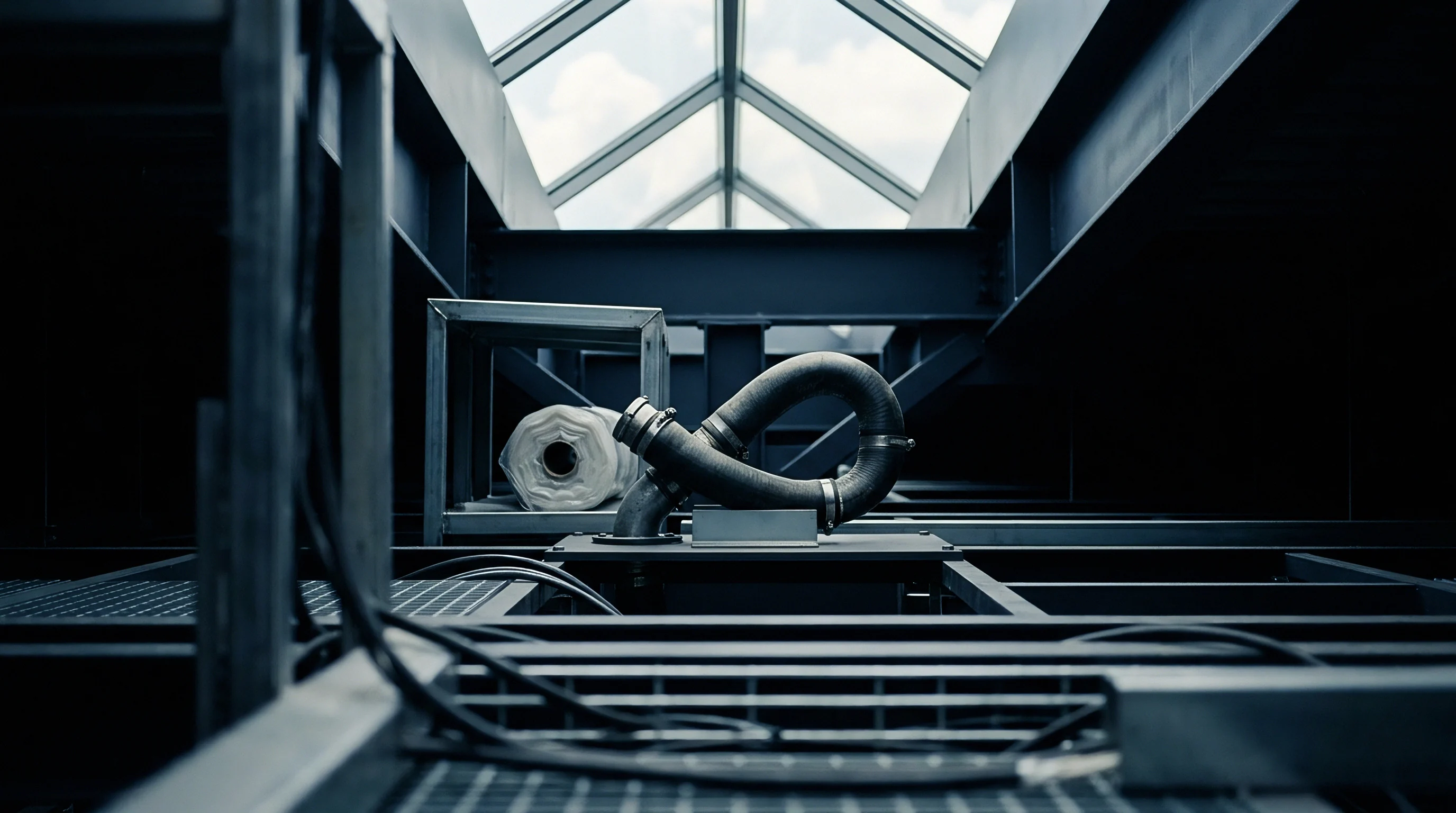
Running electrical busways and compressed air lines through shared overhead trusses requires clear physical separation and structural isolation. Busways generate substantial heat under heavy load, warming the surrounding air near ceiling structures. Pneumatic lines running too close experience air density shifts, higher condensation, and faster seal degradation in quick-disconnect fittings.
Maintaining at least 300 millimeters of clearance between busway housings and air lines prevents unwanted thermal transfer.
Busways require dedicated trapeze supports designed to handle dynamic magnetic forces during short circuits while allowing for axial thermal expansion. Copper expands at 16.5 micrometers per meter per kelvin, and aluminum expands at 23.1 micrometers per meter per kelvin. Over a 60-meter aluminum busway run, a 35-kelvin temperature rise from operation causes more than 48 millimeters of movement.
Bolting busways directly to building steel without slide-guide hangers leads to buckling, open joints, and insulation failure.
Standard engineering practice separates high-current overhead busway runs from pneumatic headers by at least 300 millimeters to isolate mechanical vibration and thermal dissipation paths.
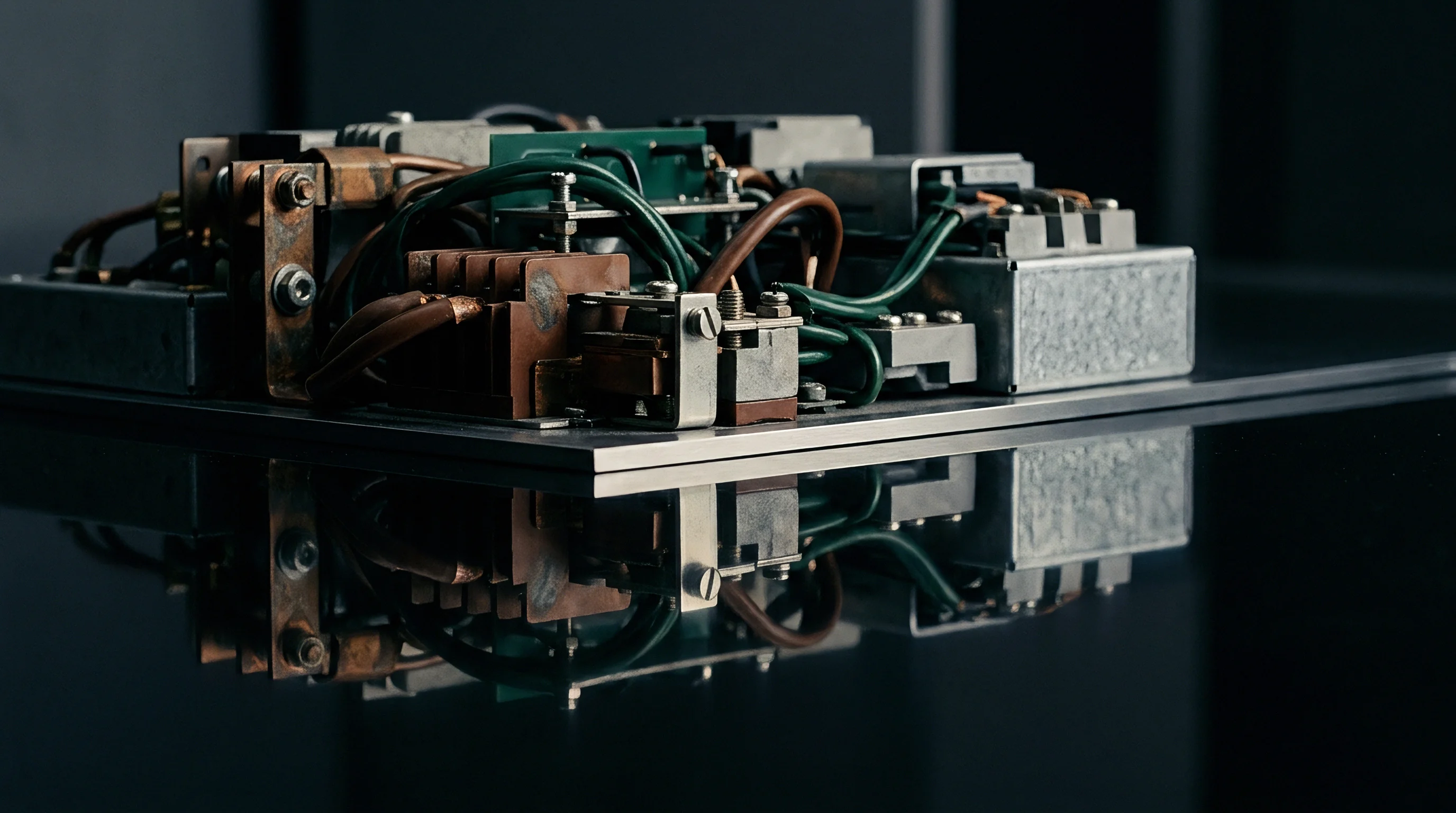
Pneumatic networks subject their supports to ongoing mechanical stress from pressure pulses, rapid valve cycles, and compressor harmonics. Fast manifold switching creates fluid shockwaves inside the pipe, sending vibration into ceiling mounts. Rigid air lines should be suspended with drop-rod hangers using neoprene isolation elements to keep kinetic energy out of the building frame.
Standard universal pipe clamps mounted on common Unistrut channel systems are often used for supporting combined utility corridors.
Margin
Confirming operational readiness across high-coincidence utility networks requires high-speed diagnostic recording during full-rate pilot runs. Standard annual maintenance audits using multimeter spot-checks and mechanical dial gauges miss sub-second transient dropouts entirely. Thorough commissioning demands synchronized digital data acquisition logging voltage waveforms, current, header pressure, and local drop velocities across every cell.
Engineers evaluate utility resilience through strict dynamic tolerance boundaries that gate full commercial production release:
- Transient voltage envelope boundaries maintain phase-to-phase voltage within positive or negative 5 percent of nominal supply rating during maximum simultaneous servo acceleration cycles.
- Pneumatic dynamic stability limits restrict instantaneous pressure drops at point-of-use tool drops to less than 0.30 bar gauge from baseline during coincident 4-tool firing sequences.
- Phase current imbalance ceilings enforce current symmetry across all three busbar phases within a 3.0 percent threshold under full automated load distribution.
- Thermal equilibrium margins verify that busway joint temperatures do not exceed a 55-kelvin rise over ambient temperature when monitored under continuous 4-hour full-rate cycle stress tests.
Building physical utility headroom into initial construction leaves room for future line changes without expensive overhauls. Sizing central busways and main air loops larger upfront adds under 12 percent to total mechanical and electrical contract costs. Retrofitting undersized utility corridors inside an active cleanroom or dense plant costs five to nine times that initial capital difference once downtime, access hurdles, and lost output are factored in.
How far can factory planners compress utility headroom margins before sub-cycle electromagnetic and fluid interactions destabilize high-density automation?