Quantifying Micro Stoppage Financial Losses Caused by Secondary Fluid Filtration Deficits in Precision Manufacturing
Secondary fluid filtration deficits drive micro stoppages that degrade precision line throughput and accumulate significant unabsorbed fixed machine overhead.
Sieve
Precision machining operations using high-speed CNC centers, thread grinders, or abrasive jet cutters depend on fluid loops to pull away heat, flush chips, and lubricate the tool edge. Primary filtration ~ chip conveyors, drag chains, or coarse magnetic drums ~ catches bulk swarf over one hundred microns. Finer debris stays in suspension, cycling continuously through delivery pumps and internal tool coolant passages.
These sub-thirty-micron metallic fines, abrasive grit, and degraded tramp oil slurries trigger subtle operational glitches across automated cells.
Particulate Entrainment and Transient Hydraulic Spikes
Suspended solids shift the effective viscosity and density of cutting fluids, disrupting flow inside high-pressure systems. As contaminated fluid moves through pumps running above seventy bar, abrasive particles score internal pistons, check valves, and relief seats. Internal leakage grows, pulling delivery pressure down during critical cuts.
Pressure switches detect these momentary drops below set thresholds and trigger automatic feed holds or tool retractions to shield carbide inserts from thermal shock.
Optical fluid sensors, pressure transducers, and flow meters on modern machine tools can misread density spikes caused by heavy particle loads. A dense cluster of metal swarf passing an inline optical sensor shifts light transmission, registering as low flow. The control unit pauses axis motion until pressure or flow readings settle back into normal ranges.
These pauses last anywhere from two seconds to forty-five seconds, leaving no error code behind other than an unallocated feed hold in the station programmable logic controller.
Fine metallic particles suspended in cutting fluid trigger optical sensor trips long before fluid temperature limits are breached.

Thermal Expansion and Automated Tool Retraction
Inadequate secondary filtration degrades the heat-transfer performance of cutting emulsions and neat oils. Suspended solids lower specific heat capacity and raise friction where the tool meets the workpiece. Recirculating microscopic swarf generates sudden thermal spikes, expanding carbide inserts past programmed dimensions.
Machine tools with active spindle load monitoring detect torque spikes from chip recutting, interpreting the extra resistance as premature wear or impending failure and triggering an immediate axis back-off.
Accuracy also suffers when fine particles plug micro-nozzles feeding thrum-coolant channels in drills and reamers. Partial blockages starve the cutting tip, driving up workpiece temperatures and forcing real-time adaptive feed reductions. Controllers scale back programmed feeds by fifteen to twenty-five percent to keep dimensions in check.
The result is an invisible capacity loss ~ cycle times stretch without raising an explicit alarm, and while the machine appears to run without interruption, daily output drops well below design capacity.
Ignoring secondary particle buildup in coolant loops accelerates wear across high-pressure delivery hardware, eventually turning minor contamination into permanent alignment loss.
Friction
Plant accounting systems routinely misclassify financial losses caused by secondary fluid contamination. Traditional ERP frameworks group downtime into planned maintenance, scheduled setup, and major breakdowns over five or ten minutes. Micro stoppages ~ transient interruptions under three minutes that resolve without maintenance ~ end up buried in unallocated efficiency variances or operator performance metrics.

Unabsorbed Overhead and Capacity Degradation
Capital-intensive plants assign fixed overhead to machining centers based on scheduled operating hours. These costs cover depreciation, facility leases, baseline utilities, and supervisory labor. When micro stoppages occur, output drops while overhead accumulates at the full hourly rate.
A cell taking forty five-second pauses per hour loses thirty minutes of productive machine time each shift. Across three shifts, four hundred operational hours disappear per station every year.
Unabsorbed overhead mounts quickly in multi-station cells. The impact goes beyond lost volume: unit costs rise as fixed expenses spread over fewer finished parts. Workpieces with tight tolerances face higher scrap rates when pauses happen mid-cut.
Thermal contraction during a two-minute spindle pause leaves visible tool marks and surface defects, forcing operators to scrap the component or send it for manual rework.
The table below models financial losses from particulate contamination across four levels of fluid cleanliness, based on standard operating conditions for automated precision grinding stations.
| ISO 4406 Cleanliness Code | Mean Particle Count per mL (>5 µm) | Micro Stoppages per Shift | Daily Unabsorbed Overhead ($) | Annual Scrapped Workpiece Cost ($) |
|---|---|---|---|---|
| 15/13/10 | 320 | 2.1 | 145.00 | 12,400.00 |
| 18/16/13 | 2,500 | 8.4 | 580.00 | 38,200.00 |
| 21/19/15 | 20,000 | 24.7 | 1,705.00 | 114,800.00 |
| 23/21/18 | 80,000 | 61.2 | 4,220.00 | 295,000.00 |
| Assumes $180/hour fully burdened machine center rate, 3 shifts per day, 300 operating days per year, 10-station automated cell line. | ||||
Quantifying Micro Stoppages in CNC Machining Cells
Calculating actual losses requires separating direct machine starvation from indirect scrap costs. Direct losses start with the station burdened rate ~ capital depreciation, power, floor space allocation, and operator labor. Multiplying that hourly rate by total micro-stoppage duration gives the direct unabsorbed overhead cost.
Indirect losses involve tracking shortened tool life alongside scrap rates. Recirculating sub-micron metal particles accelerate abrasive wear, cutting into grinding wheel dressing intervals and insert life. Tooling expenses rise thirty to fifty percent when secondary loops operate above ISO 4406 code 20/18/15.
Inspection logs show a direct link between particle saturation and out-of-roundness defects in cylindrical grinding.
Micro-stoppages under three minutes account for up to twenty-eight percent of total unallocated machine downtime in automated precision grinding operations.
Equipment output guarantees hold valid only when fluid particulate levels remain below specified threshold limits in ISO 4406 testing.


Audit
Tracking micro-stoppages requires measurement tools capable of catching millisecond-level PLC signal changes alongside continuous fluid monitoring. Standard OEE dashboards routinely filter out events under thirty seconds, labeling minor pauses as operator delay or material handling waits. Uncovering actual machine state transitions requires auditing the underlying control architecture.
Diagnostic Records and Fluid Cleanliness Metrics
Fluid evaluation relies on optical particle counters, gravimetric patch tests, and kinematic viscosity measurements. ISO 4406 measures particle concentration across three size thresholds: four, six, and fourteen microns. Standard primary filtration often operates at ISO 22/20/17, representing over four million particles larger than four microns per milliliter.
High-precision spindle bearings, high-pressure coolant swivels, and sub-micron grinding demand cleanliness levels around ISO 14/12/09.
Continuous inline particle monitoring links particulate spikes directly to machine feed holds. Laser optical sensors mounted on pump delivery lines capture particle surges that coincide with tool retractions. Maintenance logs rarely cross-reference fluid reports against PLC fault registers, masking the connection between fluid quality and mechanical uptime.
Compliance with ISO 4406 fluid cleanliness targets reduces hydraulic valve spool binding and transient line pauses by over forty percent.
Root cause diagnostics must systematically evaluate electrical and mechanical failure mechanisms within automated cells:
- Overtravel false trips happen when particle buildup inside linear encoder covers scatters optical laser signals, forcing emergency axis halts.
- Optical sensor occlusion occurs when oil mist mixed with fine swarf coats proximity switches, triggering continuous low-level faults.
- Pressure switch oscillation develops when dirty fluid clogs sensor diaphragm orifices, causing erratic pressure readings and feed holds.
- Tool load monitor spikes occur when recirculated swarf wedges between cutter flutes and the workpiece wall, mimicking tool breakage.

Why Do Standard Machine Log Registers Fail to Capture Micro Losses?
PLCs store transient faults in volatile buffer memory, overwriting entries once an operator resets the signal or the control routine clears the fault. Standard factory telemetry platforms sample operating states every ten seconds to one minute. A four-second stoppage between polling cycles slips past data acquisition entirely, leaving no record on executive production reports.
Operators often adjust feed hold overrides or bypass tool sensors to keep lines moving when dirty fluid triggers repeated alarms. Overriding safety monitors stops micro pauses but accelerates spindle failures, tool breakage, and scrap. Audit teams evaluating facilities must cross-check recorded telemetry against raw electrical draw patterns and high-frequency sensor traces to uncover true stoppage rates.
Transient machine pauses often get attributed to natural casting variations or raw material hardness inconsistencies rather than fluid quality degradation inside secondary coolant circuits.

Mesh
Secondary filtration architectures place specialized hardware downstream of primary chip separators to capture sub-twenty-micron particulate matter. Choosing media depends on fluid type, flow requirements, chip chemistry, and target cleanliness ratings. Integration requires balancing pressure drops across filter elements against pump delivery limits.
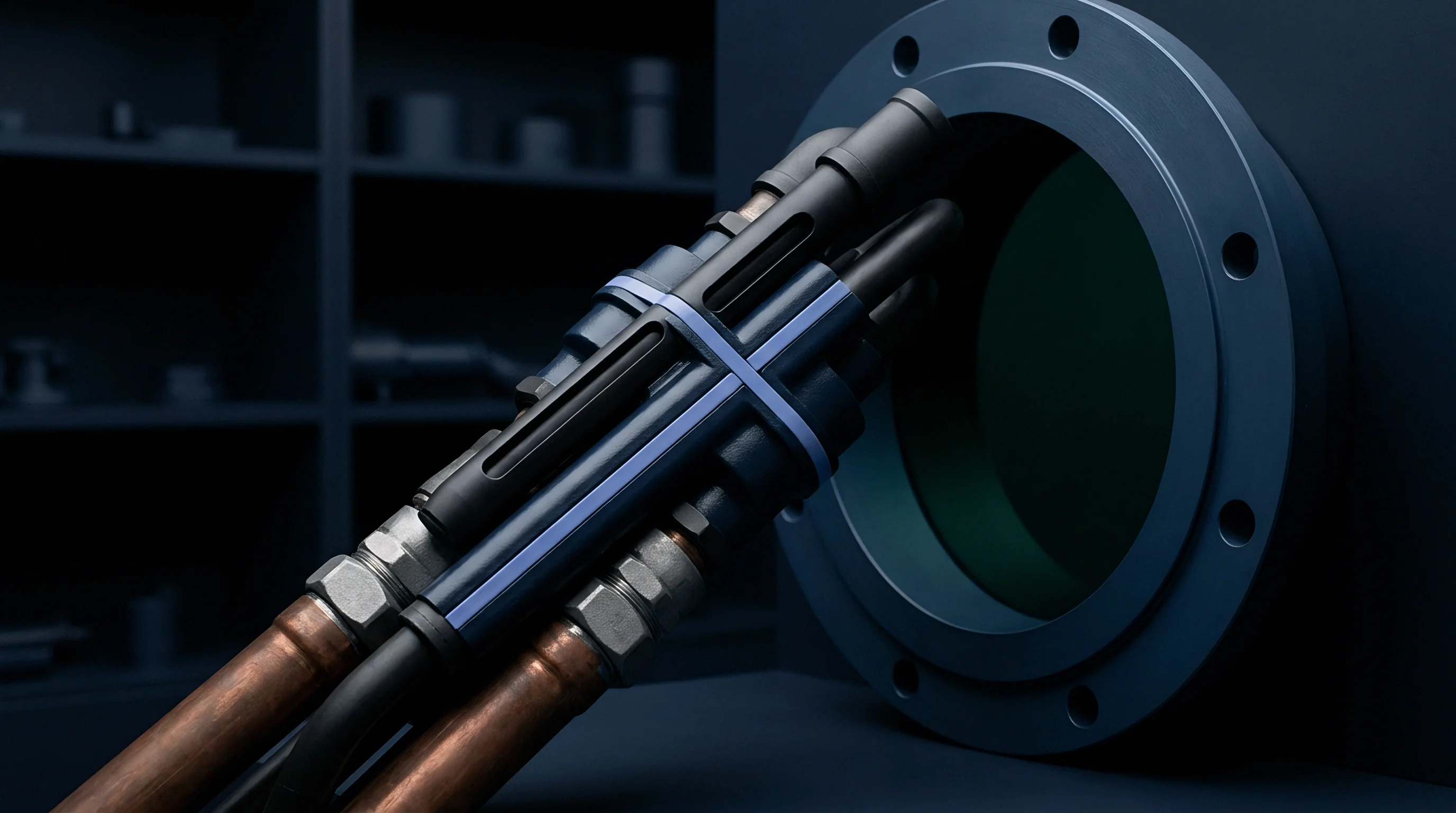
Beta Ratios and Secondary Filtration Architectures
Filter element performance is governed by the Beta Ratio ~ the count of particles of a given size upstream divided by the count downstream. A Beta rating of two hundred at ten microns means ninety-nine and a half percent of particles ten microns or larger are caught. Precision secondary loops require Beta ratios of one thousand or greater for targeted particle sizes to eliminate sensor-tripping fines.
Depth media, bag filters, high-intensity magnetic separators, and automated backwash disc systems are the primary choices for secondary coolant loops. Synthetic depth media offers high dirt-holding capacity, trapping fine particles throughout its thickness rather than just on the outer surface. Dynamic backwash systems maintain steady differential pressure, preventing flow starvation at the spindle.
| Filtration Mechanism | Target Particle Size (µm) | Beta Ratio Capability | Differential Pressure Impact | Media Consumption Cost |
|---|---|---|---|---|
| Reusable Stainless Mesh | 25 – 50 | Beta 50 | Low (0.2 – 0.5 bar) | Low (Washable) |
| Polypropylene Depth Bag | 10 – 25 | Beta 200 | Medium (0.5 – 1.5 bar) | Medium (Disposable) |
| Rare-Earth Magnetic Drum | 1 – 15 (Ferrous) | Beta 500+ | Negligible ( | Very Low (Continuous) |
| Automated Backwash Disc | 5 – 15 | Beta 1000 | Stabilized (0.8 – 1.2 bar) | High Initial / Low Running |

Magnetic Separation versus Depth Media Efficiency
Ferrous metalworking applications, like automotive gear grinding and steel turning, benefit significantly from rare-earth magnetic separation upstream of media filters. High-intensity neodymium magnetic fields pull sub-five-micron iron and steel particles from oil slurries without using disposable media. Removing ferrous solids magnetically extends consumable bag life by three hundred to five hundred percent, cutting recurring maintenance costs.
Non-ferrous materials such as aluminum alloys, titanium, and composite dust require mechanical barrier media. Continuous drum vacuum filters using disposable paper or synthetic media provide sharp particle size cutoffs, keeping fluid tanks clear of light alloy debris. Sizing secondary pumps requires accounting for clean-element pressure drop plus terminal pressure drop under heavy loading to maintain coolant volume during peak cuts.
Implementing effective secondary filtration requires a systematic, step-by-step protocol across target production lines.
- Extract fluid samples from active machine sumps during peak thermal cycles under maximum production load.
- Measure baseline particle size distribution using laser optical counting and gravimetric patch testing per ISO 4406 standards.
- Determine minimum allowable particle size limits based on spindle center coolant passage dimensions and tool sensor tolerances.
- Select secondary filtration hardware matching line flow requirements and targeted Beta ratios for identified contaminant sizes.
- Install continuous differential pressure monitoring across filter vessels wired directly into cell PLC safety circuits.
- Establish automated maintenance alerts triggered when differential pressure reaches seventy-five percent of maximum rating.
Sizing filter elements for nominal flow without accounting for viscosity spikes during cold morning startups leads directly to pump cavitation and open bypass valves.

Capital
Justifying secondary filtration requires turning reduced micro-stoppages into clear financial returns. Business cases must balance capital expenditures for upgrades against unabsorbed fixed overhead, tool replacement costs, and scrap rates. Proposals backed by empirical fluid diagnostic data move far faster through capital approval cycles.
Investment Justification and Stage Gate Verification
Calculating payback periods for secondary fluid systems starts with quantifying recovered line capacity. Reclaiming twenty minutes of machine availability per day across a ten-machine cell adds one thousand operating hours annually. At a conservative rate of one hundred fifty dollars per hour, that capacity recovers one hundred fifty thousand dollars in unabsorbed overhead per year.
Purchase and installation costs for centralized secondary filtration units typically run sixty to eighty thousand dollars per cell.
Implementation plans should pass through verification stage gates before scaling capital commitments across full production lines:
- Fluid particle baseline audit confirms baseline contamination exceeds ISO 4406 targets and correlates directly with recorded feed holds.
- Micro-stoppage logging verification confirms that high-speed PLC diagnostic registers track short pause frequencies accurately.
- Secondary loop flow margin proves installed pump capacity maintains target coolant pressure under maximum filter cake loading.
- Scrap reduction threshold demonstrates at least a twenty percent reduction in surface finish defects during single-machine pilot trials.
Unresolved coolant contamination shifts production costs directly into premature tool wear and unrecoverable cycle delays.

Worked Financial Model for Coolant Loop Retrofitting
Consider an automated machining cell containing four CNC horizontal machining centers running three shifts (6,000 operational hours per machine annually). Baseline logging reveals an average of six micro stoppages per machine shift, averaging ninety seconds per event. The fully burdened cell operating rate is $220 per hour.
Annual micro-stoppage hours per machine equal 6 events per shift times 3 shifts per day times 250 operating days per year times 1.5 minutes per event, divided by 60 minutes per hour, yielding 112.5 lost machine hours annually. Across four machines, total lost time equals 450 hours per year. Multiplying 450 hours by the $220 burdened rate produces $99,000 in unabsorbed fixed overhead loss every year.
Installing a dedicated secondary depth filtration system with magnetic pre-separation costs $34,000 in hardware plus $8,000 for line integration and installation, totaling $42,000 in initial capital expenditure. Consumable filter bag replacements and auxiliary pumping power run $6,000 per year. Pilot testing shows a seventy-five percent reduction in micro stoppages, recovering $74,250 in unabsorbed overhead annually.
Net annual savings equal $74,250 in recovered overhead minus $6,000 in operating expenses, leaving a $68,250 net annual benefit. Dividing the $42,000 capital cost by the $68,250 net benefit produces a payback period of 7.38 months. Discounted cash flow analysis over a five-year lifespan at a ten percent cost of capital yields a net present value exceeding two hundred thousand dollars.
What specific threshold of fluid cleanliness yields the best economic balance between filter element consumption costs and capacity recovery in high-volume aluminum aerospace machining?