Diagnostic Procedures for Root Cause Analysis of Secondary Fluid Contamination Losses
Root cause diagnosis of secondary fluid contamination requires continuous volume logging, spectrometric chemistry screening, and segmental pressure testing.
Sump
Closed-loop thermal management circuits reveal mechanical trouble first through physical volume shifts at the head tank. A plant running five hundred liters of synthetic polyalphaolefin or inhibited propylene glycol per minute across battery pack cooling plates or chemical reaction jackets depends on hydraulic equilibrium. When the head tank level rises without operator top-up, process mass is migrating past physical barriers into the cooling stream.
When the level drops while system pressure holds steady, cooling media is entering the product stream or flashing across pinhole leaks in low-pressure exchangers. Chilled water circuits lose thermal margin quickly. Unplanned inventory changes always precede laboratory confirmation of chemical degradation.
Operators frequently overlook slow, continuous fluid ingress because automated level-make-up valves mask the volumetric loss. A line operator logging a daily three-liter addition to an ethylene glycol loop often assumes evaporation from an open vented reservoir. Evaporative losses in sealed or blanketed circuits remain near zero under continuous 45 degree Celsius return temperatures.
The recorded make-up volume represents continuous migration across failing mechanical boundaries.
Secondary fluid loss accelerates once suspended solids blind the internal plate channels.
Fluid Inventory Inversion at the Expansion Vessel
Diagnostic triage starts with manual isolation of automatic make-up lines and nitrogen blanketing regulators. Technicians log the sight-glass graduation at ten-minute increments across two operating shifts under full thermal load. A rising liquid column during steady chiller operation identifies higher-pressure process fluid crossing the primary boundary.
High-viscosity process slurry or oil displaces secondary heat transfer fluids when pump head pressures exceed the secondary circuit return line pressure by more than 0.8 bar gauge.
Contamination manifests physically in the expansion vessel long before main chiller compressors trip on high condensing pressure. Secondary cooling media under cross-contamination exhibits distinct surface scum, emulsification layers, or severe discoloration. A dark layer floating on water-glycol mixtures indicates lubricating oil migration from compressor drive shafts or circulation pump mechanical seals.
The heat transfer coefficient drops. Heavy particulate settling at the bottom cone points to cross-circuit scale washing out of plate-and-frame evaporators.

Thermal Derating Linked to Secondary Loop Particulates
Particulate deposition on high-density cooling blocks destroys heat transfer efficiency within hours of initial ingress. When solids breach secondary fluid circuits, Reynolds numbers drop as channel geometries narrow. Viscosity shifts alter flow profiles.
Laminar boundary layers thicken from 0.05 millimeters to over 0.35 millimeters, degrading thermal transfer rates between cooling channels and target components. Operators attempt to restore cooling capacity by ramping circulation pump speed, which elevates system operating pressures and accelerates the leak rate across damaged internal heat exchanger walls.
Line logs capture this degradation through widened approach temperatures across plate exchangers. A clean system maintains a 1.5 to 2.0 Kelvin approach temperature between secondary fluid supply and process fluid return. Contaminated secondary fluids present widening approach deltas expanding past 5.5 Kelvin under identical thermal kilowatts.
Sediment blinds the plate channels. Pumping power surges by 18 to 27 percent while delivered cooling tonnage falls.
Original equipment builders consistently explain away sudden viscosity shifts and heat transfer losses as normal inhibitor exhaustion or routine atmospheric dust contamination.

Screening
Laboratory quantification separates background fluid aging from genuine external contamination ingress. Secondary fluids degrade naturally over four to six years through thermal stress and oxidation, but cross-contamination cuts fluid working life to days. Determining the exact source demands a structured fluid analysis schedule executed within four hours of observed thermal or volumetric shifts.
Field personnel draw duplicate representative samples from the expansion vessel midpoint and the discharge header of the main circulation pump while the fluid circulates at normal operating temperature.
Cold sampling produces misleading particulate and sediment readings because heavy contaminant phases drop out of suspension in stagnant headers. Technicians use clean, fluorinated ethylene propylene bottles purged with dry nitrogen to prevent atmospheric moisture pickup. Glycol acidifies under continuous aeration.
Immediate bench measurements of pH, refractive index, and electrical conductivity isolate baseline fluid breakdown from foreign fluid intrusion.
Analytical Test Batteries for Secondary Coolants
Detailed forensic chemistry relies on four standardized laboratory tests to identify foreign compounds within secondary loops. Standard ASTM test methods define the threshold limits for chemical verification.
| Test Parameter | Analytical Standard | Normal Coolant Baseline | Contamination Ingress Signature | Root Cause Indication |
|---|---|---|---|---|
| Kinematic Viscosity (40°C) | ASTM D445 | 4.2 to 4.8 mm²/s | Elevated to > 6.5 mm²/s | Heavy hydraulic oil ingress |
| Water Content | ASTM D6304 (Karl Fischer) | < 100 mg/kg (Dielectric) | Spike to > 1,200 mg/kg | Chilled water cross-leakage |
| Acid Number | ASTM D664 | < 0.10 mg KOH/g | Rapid climb to > 0.85 mg KOH/g | Refrigerant breakdown or acid ingress |
| Elemental Composition | ASTM D5185 (ICP-OES) | < 5 mg/kg wear metals | Fe > 45 mg/kg, Cu > 25 mg/kg | Galvanic attack from mismatched fluids |
| Particle Size Distribution | ISO 4406 | Scale 15/13/10 | Scale 22/19/16 or worse | Failing pump seals or filter breach |
| Values reflect industrial water-glycol and dielectric synthetic hydrocarbon systems operating at 35°C to 65°C nominal loop temperatures. | ||||
Chemical screening must differentiate internal corrosion debris from true secondary fluid loss caused by external fluid blending. An elevated iron concentration accompanied by normal fluid viscosity indicates aggressive chemical erosion of carbon steel piping manifolds. Elevated iron paired with a sharp viscosity drop and a suppressed flash point reveals process hydrocarbon dilution entering the secondary fluid system from high-pressure reactor seals.
Can Spectrometry Distinguish Process Ingress from Additive Depletion?
Fourier-transform infrared spectrometry identifies organic chemical functional groups that do not belong in the base thermal fluid formulation. Inhibited water-glycol coolants carry specific carboxylate or silicate inhibitor packages exhibiting clear infrared absorption bands between 1550 and 1600 reciprocal centimeters. When ester-based synthetic lubricants cross the heat exchanger boundary, distinct ester carbonyl peaks emerge sharply at 1735 to 1750 reciprocal centimeters.
Spectrometric screening reveals foreign chemistries at concentrations as low as 0.05 percent by volume.
Inductively coupled plasma optical emission spectrometry tracks elemental tracers characteristic of process fluids. Silicon concentrations rising past 30 parts per million in a coolant formulated without silicate stabilizers confirm silicone heat transfer fluid ingress or defoamer contamination. Phosphorus spikes above baseline point directly to hydraulic fluid ingress from adjacent actuator systems.
Physical particle counting under ISO 4406 establishes the severity of solids contamination circulating through the cooling distribution channels. Clean secondary fluid circuits operate at or below 16/14/11 cleanliness codes. Ingress of process solids drives counts beyond 21/18/15 within single production shifts.
Particulate loading blinds five-micrometer inline filtration units, forcing bypass valves open and distributing abrasive solids directly into pump bearings and high-precision heat sinks.
- Refractive Index Shifting demonstrates bulk water dilution or glycol concentration changes outside manufacturer operating bands.
- Potentiometric Acid Titration detects organic acids generated by glycol thermal cracking or cross-circuit acid migration.
- Colorimetric Indicator Strips offer immediate qualitative verification of nitrite and molybdate inhibitor concentrations across plant headers.
- Gas Chromatography Mass Spectrometry pinpoints trace volatile solvents crossing from primary solvent cleaning operations into common utility chill loops.
According to ASTM D3306 specifications, a reserve alkalinity falling below 10 milliliters of 0.1 Normal hydrochloric acid signals rapid fluid acid neutralization and active chemical contamination.
Section 8.4 of the standard fluid supply agreement invalidates supplier thermal performance guarantees whenever circulating particulate exceeds ISO 18/16/13 limits.

Breach
Physical inspection of the fluid boundary isolates the exact component permitting cross-contamination. Heat exchangers, circulation pump mechanical seals, and shared multi-circuit utility headers form the primary breach vectors. Plate-and-frame and brazed plate heat exchangers experience micro-fissures driven by thermal fatigue and pressure hammer.
Microcracks propagate through grain boundaries. When high-pressure process pumps cycle on and off, hydraulic shock waves generate brief pressure spikes up to four times nominal operating levels.
Plate packs deflect under pressure surges. Gaskets compress unevenly, allowing fluid weeping across sealing channels designed to vent leaks externally. When vent passages plug with dried coolant salts or external paint, leaking fluid flows directly past the secondary elastomeric gasket barrier into the alternate fluid channel.
Brazed plate units suffer pinhole failures along nickel or copper braze joints exposed to chloride-bearing fluids.

Differential Pressure Transients across Heat Exchanger Plates
Cross-contamination requires a driving force, which is almost always a transient differential pressure inversion. Facility designs generally specify that the secondary cooling loop operate at a higher pressure than the process fluid loop to guarantee that any boundary failure results in coolant entering the process rather than process contaminants entering the cooling infrastructure. In practice, line start-ups, filter switching operations, and valve actuations invert this pressure differential for seconds or minutes at a time.
High-speed pressure transmitters logging at one hundred hertz expose these transient inversions that standard SCADA scanning intervals miss entirely. During emergency stops, secondary circulation pump discharge pressure collapses to static head pressure within 800 milliseconds. If the process line retains pneumatic or accumulator pressure, process fluid drives backward across micro-cracks into the depressurized secondary line.
The seal faces run hot.
| Diagnostic Technique | Execution Medium | Minimum Detectable Leak Rate | Interruption Scope |
|---|---|---|---|
| Helium Mass Spectrometry | Helium tracer at 4 bar gas | 1 × 10⁻⁸ mbar·L/s | Complete offline evacuation required |
| Differential Pressure Decay | Dry nitrogen at 6 bar gas | 0.05 bar over 30 minutes | Circuit isolated and drained |
| Fluorescent Dye Injection | UV-reactive organic dye | 5 mL/hr liquid migration | Online under full operational flow |
| Acoustic Emission Testing | High-frequency piezo sensors | Turbulent orifice leaks > 0.1 mm | Online without process interruption |

Is Mechanical Seal Barrier Fluid Crossing the Boundary?
Circulation pumps utilizing dual-pressurized mechanical seals introduce barrier fluid into the secondary coolant loop when barrier pressure regulation fails. API Plan 53A and 54 support systems maintain barrier fluid pressure 1.5 to 2.0 bar above pump stuffing box pressure to lubricate seal faces. Cavitation erodes the impeller vanes.
When seal faces wear or experience thermal distortion, barrier fluid migrates continuously across the inner seal face into the secondary fluid.
If plant maintenance teams fill seal barrier reservoirs with generic turbine oils instead of specified synthetic fluids compatible with the secondary coolant, the coolant suffers rapid hydrocarbon contamination. The oil emulsifies with water-glycol mixtures, coating temperature sensor wells and creating false thermal feedback. Heat transfer surfaces foul rapidly as insolubles precipitate out of the emulsion.
- Elastomer Swell Verification confirms whether seal O-rings have absorbed secondary fluid components, altering cross-sectional thickness and causing seal face misalignment.
- Barrier Reservoir Level Audits track lubricant volume changes against pump runtime hours to measure inner seal face leakage rates directly.
- Face Flatness Optical Bench Scans reveal thermal warping exceeding two helium light bands across disassembled silicon carbide seal rings.
- Stuffing Box Flush Differential Logging identifies pressure inversions where process fluid overcomes flush injection pressures, carrying abrasive solids directly into the seal interface.
A pressure inversion of 0.4 bar sustained for twelve seconds across a fractured 0.2-millimeter braze seam transfers roughly 85 milliliters of high-viscosity process fluid directly into the secondary circuit.
Failure to identify and seal these micro-fissures leads to complete line contamination, requiring thousands of liters of specialized coolant disposal, disposal charges for hazardous chemical mixtures, and weeks of unscheduled plant downtime.

Isolation
Pinpointing the compromised heat exchanger or pump requires segmental isolation rather than indiscriminate bulk fluid replacement. Draining and refilling a ten-thousand-liter cooling loop without isolating the breach simply contaminates the fresh fluid charge within forty-eight hours. The diagnostic procedure systematically isolates sections of the secondary fluid distribution piping using double-block-and-bleed valve arrangements.
Technicians monitor each isolated zone under static pressure holding tests while checking fluid samples for chemical stabilization.
Stepwise isolation begins at the furthest process branch lines, moving progressively inward toward the central cooling plant. By valving off individual production tools while the main loop circulates, technicians monitor whether contaminant accumulation rates slow or cease entirely. Online total organic carbon analyzers and refractive index monitors installed on the main return manifold register the precise minute an active contamination source is valved out of the circuit.
Segmental Hydraulic Block Tests
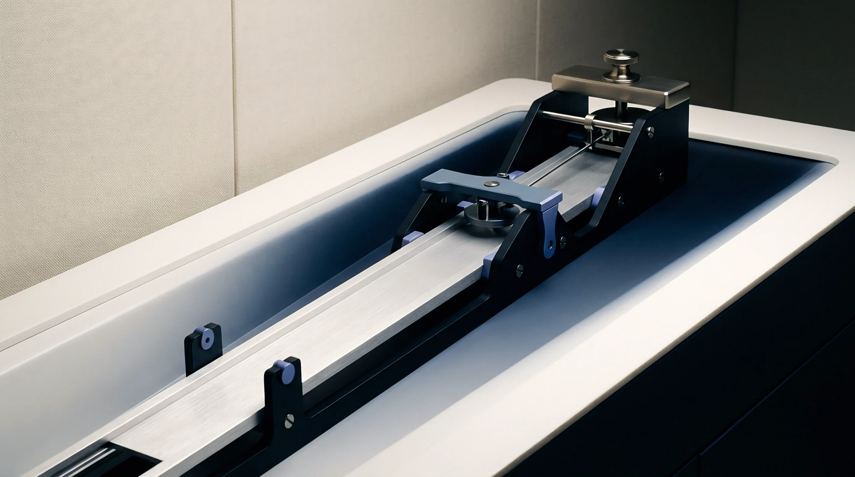
Each isolated segment must undergo hydrostatic or pneumatic decay verification to confirm boundary integrity. Technicians disconnect process connections on the opposing side of the heat exchanger, opening shell vents to atmospheric drainage. A secondary loop segment pressurized to 1.5 times nominal operating pressure must hold pressure with zero decay over a four-hour observation window.
Any liquid discharge from open process-side drain ports confirms that the internal heat transfer wall is breached.
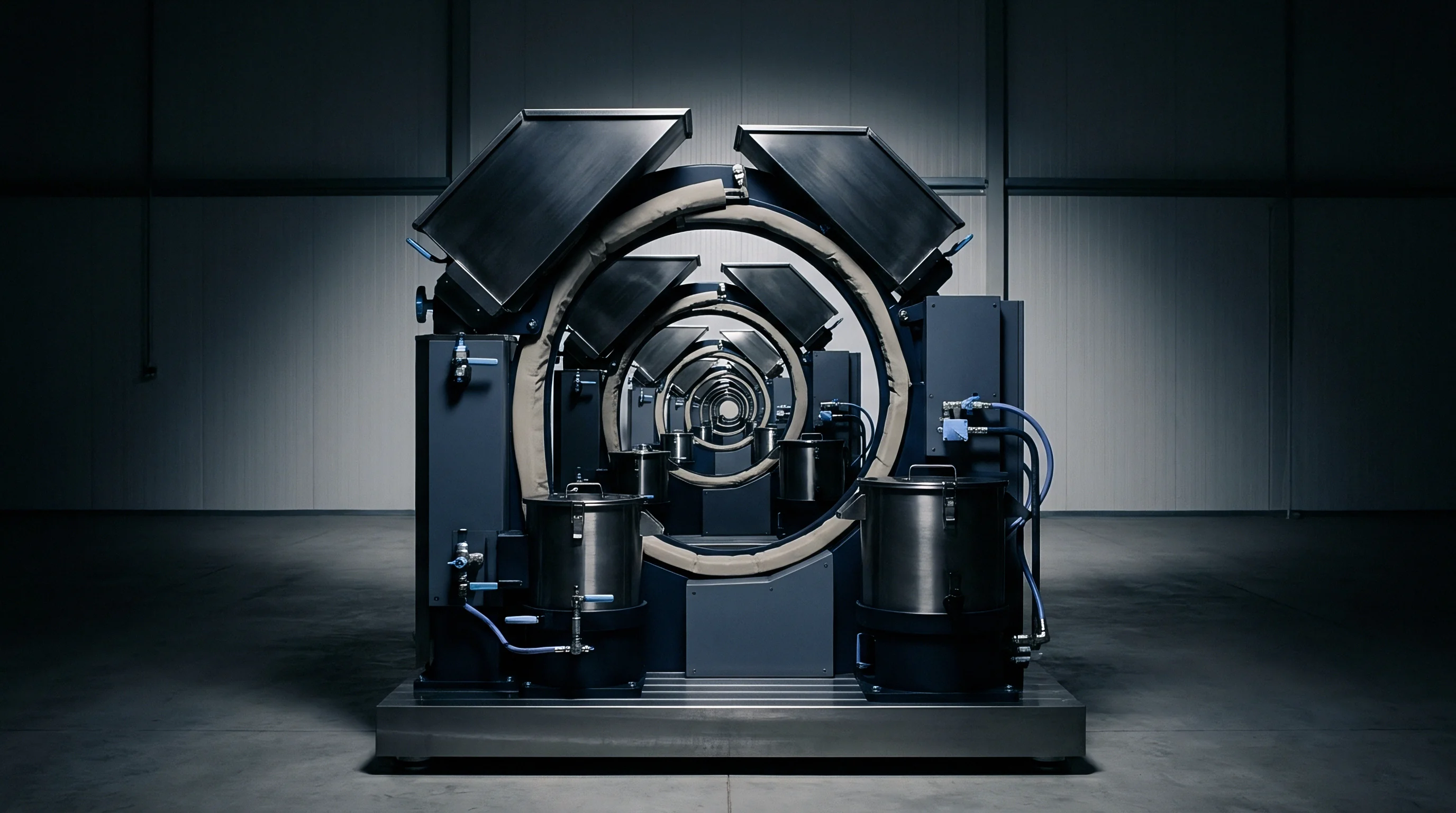
High-capacity systems require specialized blind flanging because isolation valves frequently weep across seats, generating false positive leakage indications. Resilient seat butterfly valves commonly used in secondary coolant loops fail to seal completely against low-viscosity glycols or synthetic oils when particulate debris lodges in the valve seat elastomer. Steel spade blinds installed between pipe flanges provide absolute physical isolation during diagnostic pressure testing.
Pre-Drain Verification Sequences for High-Volume Systems
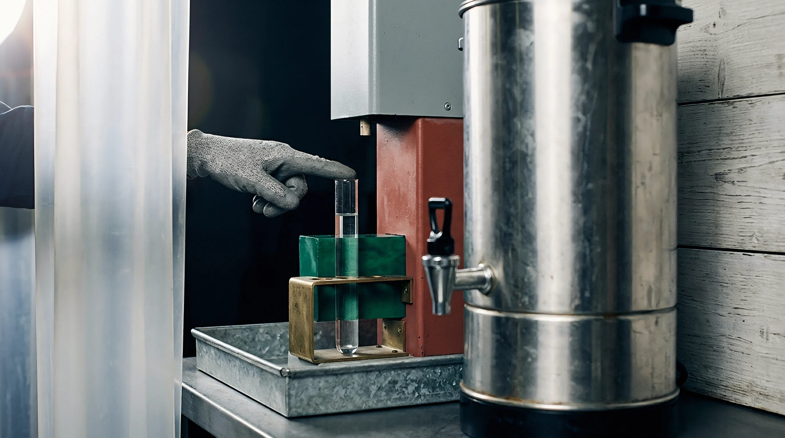
Before committing capital to wholesale fluid drainage, plant engineering conducts a rigorous five-step isolation verification sequence to ensure that every leaking boundary is mapped.
- Baseline Return Sampling establishes the exact concentration of foreign chemicals circulating through the central distribution manifold before closing branch valves.
- Branch Isolation Gating closes flow to individual heat exchange stations for sixty minutes each while recording system pressure profiles.
- Sidestream Fluorometric Detection tracks the concentration decay of background markers as suspected breach branches leave the circulating volume.
- Process-Side Cavity Inspection opens inspection ports on the product side of isolated exchangers to check for secondary coolant accumulation under static fluid head.
- Cross-Boundary Pressure Profiling raises process circuit pressure while secondary circuits remain vented to verify the direction and threshold of fluid migration.
Blindly dumping a contaminated loop without completing segmental isolation guarantees that the replacement fluid will meet the same fate.

Recovery
Restoring a contaminated secondary fluid circuit demands aggressive chemical purging before introducing virgin heat transfer fluid. Draining an industrial circuit leaves up to fifteen percent of the total volume trapped in low-point pipe drops, valve pockets, and horizontal exchanger channels. If the residual fluid contains five percent oil or process cross-contaminants, the newly introduced coolant immediately falls out of specification.
Decontamination requires multi-stage displacement flushes combined with alkaline or solvent-based flushing agents.
Flushing dynamics depend on achieving fully turbulent flow throughout all parallel legs of the piping network. The circulating wash fluid must maintain a Reynolds number above 4,000 across every circuit branch to physically lift settled particulates and scour internal pipe walls. Pumps sized purely for nominal laminar or transitional cooling duty frequently lack the motor power or volumetric capacity to generate scouring velocities during high-viscosity flush passes.

Displacement Velocity and Residual Solvent Dilution
Flushing proceeds through three distinct phases: chemical breakdown of residual contaminants, water or solvent displacement rinsing, and final fluid charging. Hydrocarbon contamination requires an aqueous degreasing wash containing non-ionic surfactants circulating at 60 degrees Celsius for minimum four hours. Residual solvent depresses the flashpoint.
The chemical flush must be completely purged from the system using demineralized water before glycol or dielectric fluid introduction. Surfactant residues remaining in secondary circuits cause severe fluid foaming, cavitation in circulation pumps, and thermal air binding in cooling blocks.
| Flushing Stage | Flushing Media | Minimum Target Velocity | Acceptance Criteria |
|---|---|---|---|
| Initial Displacement | Low-cost sacrificial glycol/water | 1.8 m/s in headers | > 95% primary contaminant purge |
| Degreasing / Wash | 2% alkaline surfactant solution | 2.2 m/s in headers | Turbidity < 5 NTU, total organics stable |
| Rinse Pass | Demineralized water (< 5 µS/cm) | 2.0 m/s in headers | Conductivity < 15 µS/cm, neutral pH |
| Final Fluid Charge | Virgin specified secondary fluid | Operational rate | Meets manufacturer technical data sheet |
Stage Gates for Return to Service
Returning a line to active manufacturing requires strict sign-off protocols governed by dated operational criteria. Chemical flushes attack elastomer gaskets. Technicians replace all system filter elements immediately following the alkaline rinse pass, stepping down from twenty-micrometer absolute filter bags to five-micrometer depth cartridges for final charging.
Laboratory testing of the final fluid charge occurs twenty-four hours after restarting circulation at full operating temperature. The sample must show complete absence of foreign hydrocarbon bands on infrared spectra, water content matching virgin fluid limits, and particle counts below ISO 16/14/11. Production restarts carry severe downside.
Differential pressure across clean heat exchanger banks must match original commissioning baseline curves within a three percent margin of error.
What remains unresolved across high-capacity thermal systems is the economic threshold where automated, permanent online contaminant detection sensors justify their integration cost over manual fluid sampling regimes on loops containing fewer than five thousand liters.