Designing Active Sub-Slab Depressurization Systems for Post-Industrial Facility Turnovers
Active sub-slab depressurization requires sizing blower head and pipe manifolds from field-measured aggregate permeability to sustain negative four pascals.
Suction
Active sub-slab depressurization balances an extraction vacuum against sub-grade pneumatic transmissivity to reverse advective vapor intrusion into industrial spaces. Industrial turnover projects convert legacy manufacturing plants, chemical processing footprints, and precision machine shops into dry distribution warehouses or light assembly plants. These conversions routinely expose incoming building occupants to chlorinated solvent vapors, volatile hydrocarbons, and recalcitrant industrial degreasers accumulating below aged concrete slabs.
Sub-slab depressurization mechanics depend on drawing sub-slab soil gas pressures below internal building ambient air pressure, maintaining continuous negative differential barometric pressure across every joint, penetration, and crack in the foundation. This differential stops toxic volatiles from entering breathing zones through foundation fractures. The dominant contaminant of concern in legacy sites remains trichloroethylene, alongside tetrachloroethylene, benzene, and degradation breakdown products.
Trichloroethylene vapor inhalation produces severe acute and chronic developmental, neurological, and immunological toxicities. Regulatory bodies enforce sub-slab vapor screening levels down to fractional microgram-per-cubic-meter concentrations. Industrial turnovers demand mechanical depressurization infrastructure designed directly from empirical field test evidence, avoiding undersized blowers or oversized, energy-wasting blower banks.
Designing sub-slab depressurization infrastructure requires balancing pneumatic conveyance with the sub-slab foundation configuration. Foundation footprints on turn-of-the-century and mid-century industrial facilities contain dense structural variations, including grade beams, machine foundation pits, internal spread footings, historic utility chases, and varied floor slab thicknesses ranging from 100 millimeters to more than 450 millimeters of reinforced high-strength concrete. These underground barriers compartmentalize the sub-slab gravel pack, creating isolated pressure envelopes.
Industrial slabs lack the uniform, high-permeability, washed pea-gravel bases seen in modern greenfield slab designs. Slabs from mid-century manufacturing sites sit directly over poorly sorted fill, crushed demolition rubble, silty sand, or native clay with low intrinsic permeability. Low intrinsic permeability severely curtails pneumatic influence, restricting air movement across the footprint.
The cross-slab static differential pressure must consistently match or exceed negative four to five pascals across the target footprint to prevent convective vapor entry into indoor breathing airspace.
Field characterization resolves pneumatic uncertainty through pilot-scale communication testing. Field engineers core test access points through the floor slab to extract soil vapor while monitoring induced vacuum responses at varying radial distances using high-precision digital micromanometers. The resulting empirical relationship between applied extraction vacuum, volumetric gas flow rate, and measured radial pressure differentials determines the radius of influence.
Calculating the radius of influence establishes suction pit density, manifold layouts, pipe friction drops, and required blower operating curves. Blower capacity specifications rely on measured sub-slab parameters rather than generic structural assumptions.
The pneumatic relationship governing sub-slab gas flow into an extraction cavity conforms to steady-state radial flow regimes through porous media, derived from Darcy’s law for compressible fluid flow. The mathematical expression relates pressure drops to soil physical properties:
Q = /
In this equation, Q represents volumetric flow rate, k represents intrinsic permeability of the sub-slab fill material, H represents the thickness of the permeable sub-slab zone, mu represents dynamic gas viscosity, P_atm represents ambient atmospheric pressure, P_w represents the absolute pressure maintained at the extraction suction pit perimeter, R_w represents the physical radius of the suction pit cavity, and R_i represents the effective radius of pneumatic influence where differential pressure reaches the minimum acceptable regulatory threshold, typically set between 4 and 10 pascals. High-vacuum low-permeability conditions compress radius of influence, increasing the required suction pit count. Conversely, washed granular stone sub-bases display high permeability, allowing broad pneumatic propagation with fewer suction pits operating under moderate blower vacuums.
Failure to map pneumatic isolation barriers during turnover creates dead zones in the sub-slab vacuum field, allowing solvent migration through interior slab joints directly into occupied warehouse workspaces.

Gravel
Sub-slab sub-base aggregate directly dictates pneumatic permeability, pressure field propagation, and extraction pit placement across the footprint. Industrial floors poured over native silty clay, reworked foundry sands, or compacted crushed concrete exhibit low intrinsic permeability values spanning 10^-12 to 10^-15 square meters. These tight materials constrain volumetric soil gas flow, requiring high vacuum levels exceeding 15 to 25 kilopascals at each extraction cavity.
High vacuum extraction in low-permeability soils produces narrow, steep pressure drawdowns, limiting the effective radius of influence to 3 to 6 meters from the suction center. Conversely, slabs poured over washed river gravel, clean crushed limestone, or ASTM No. 57 aggregate display intrinsic permeabilities spanning 10^-9 to 10^-11 square meters. High-permeability aggregate allows sub-slab vacuums between 500 and 1,500 pascals to propagate 15 to 30 meters out from an extraction point, drastically lowering the physical suction pit density across open square footage.
Pneumatic communication testing quantifies field-scale intrinsic permeability across heterogeneous sub-slab strata. The diagnostic procedure deploys a temporary pilot extraction point, typically a 76-millimeter to 102-millimeter cored borehole completed into the sub-slab gravel pack. Vacuum application through a portable regenerative blower or high-flow industrial vacuum test rig draws controlled air volumes across varied pressure steps.
Technicians monitor differential vacuum responses across an array of sealed sub-slab vapor observation pins drilled at logarithmic distance intervals along perpendicular radial vectors. Engineers track differential pressures across the floor slab using differential pressure transmitters with resolutions down to 0.1 pascals. Connecting transient pressure step responses to steady-state drawdowns isolates localized flow boundaries, utility gravel corridors, and subsurface structural grade beams that arrest pressure extension.
| Sub-Base Aggregate Classification | Intrinsic Permeability (m^2) | Typical Extraction Vacuum (kPa) | Unit Flow per Pit (m^3/h) | Observed Radius of Influence (m) |
|---|---|---|---|---|
| Washed Crushed Aggregate (ASTM No. 57) | 5.0 x 10^-10 to 1.0 x 10^-9 | 0.5 to 1.5 | 85 to 210 | 18 to 32 |
| Clean Pea Gravel (ASTM No. 8) | 1.0 x 10^-10 to 4.5 x 10^-10 | 1.0 to 2.5 | 60 to 140 | 14 to 22 |
| Poorly Graded Sand Fill with Silt | 5.0 x 10^-12 to 5.0 x 10^-11 | 4.0 to 9.0 | 25 to 65 | 6 to 12 |
| Compacted Crushed Demolition Fills | 1.0 x 10^-13 to 8.0 x 10^-12 | 8.0 to 18.0 | 15 to 40 | 4 to 8 |
| Native Silty Clay with Reworked Till | 1.0 x 10^-15 to 5.0 x 10^-14 | 15.0 to 28.0 | 5 to 18 | 1.5 to 4 |
A post-industrial tenant turnover at a 12,000-square-meter stamping plant demonstrates the direct operational relationship between aggregate variability and system layout. Historical layout drawings documented a uniform 150-millimeter gravel bed below the interior slab. Pilot diagnostic communication testing across four building quadrants revealed unexpected spatial divergence in pneumatic response.
The southern quadrants, built directly over undisturbed ASTM No. 57 crushed stone, demonstrated an average intrinsic permeability of 6.2 x 10^-10 square meters. The extraction test rig applied 1.1 kilopascals of vacuum at 110 cubic meters per hour, generating a 6-pascal negative pressure response at a radial distance of 24 meters from the core hole. This high permeability enabled the designer to cover the 6,000-square-meter southern quadrant with six primary suction points.
The northern half of the facility sat over dense crushed brick and masonry debris blended with dense silty clay. Intrinsic permeability across the northern zones dropped to 2.1 x 10^-13 square meters. Diagnostic testing confirmed that pulling 16 kilopascals of vacuum moved only 22 cubic meters per hour, with the 5-pascal boundary collapsing to 5.2 meters from the test point.
Overcoming this severe physical restriction required twenty-four independent extraction pits or horizontal directional drilled suction laterals across the 6,000-square-meter northern floor to achieve verified pressure communication across the footprint. Omitting diagnostic communication testing across distinct building wings leads straight to under-designed blower hardware, unmitigated indoor solvent accumulation, and unexpected capital expenditures during turnover validation.
Contractual turnover specifications that require five pascals of differential pressure without referencing gravel permeability create open-ended commercial liabilities during sub-slab blower balancing.
Gravel depth directly regulates the total cross-sectional volume of the soil gas conveyance reservoir. Thin aggregate layers under 50 millimeters induce severe entry headloss, choking radial pneumatic flow toward the extraction pipe. Excavating a localized 150-liter sump below the slab and backfilling the cavity with clean crushed granite expands the intake surface area, lowering soil face velocities to reduce particulate entrainment into the blower stream.
The aggregate bed dictates whether active sub-slab depressurization operates through low-vacuum high-flow regenerative units or requires high-vacuum low-flow positive displacement blowers.
Rigging
Hardware configuration and conveyance pipe routing form the operational backbone of an active sub-slab depressurization network. The extraction manifold gathers soil gas from suction cavities distributed across the floor, channeling toxic vapors up through risers, overhead collector headers, drop traps, and into the mechanical exhaust plant. Manifold line sizing balances interior fluid velocity against cumulative frictional pressure head loss.
Maintaining air velocities between 5 and 15 meters per second ensures dynamic movement of humid air without driving excessive pipe friction losses. Air speeds below 4 meters per second permit condensed water vapors to pool in low pipe bellies, creating liquid dams that starve vacuum propagation. High velocities exceeding 18 meters per second create severe acoustic noise through interior roof trusses and introduce steep parasitic frictional losses across line elbows, reducing available suction at distant slab points.
Pipe material selection depends entirely on chemical compatibility with extracted volatile organic compounds and facility fire safety codes. Polyvinyl chloride (PVC) Schedule 40 or Schedule 80 piping remains an industry standard for standard extraction applications. PVC offers high structural rigidity, simple solvent welding, and excellent corrosion resistance against damp underground air.
High concentrations of chlorinated solvents, particularly pure-phase trichloroethylene and tetrachloroethylene, will soften and degrade standard PVC over continuous operation. Industrial facilities carrying aggressive solvent vapors or placing pipe drops through hazardous work zones switch to high-density polyethylene (HDPE), stainless steel, or chlorinated polyvinyl chloride (CPVC). Exterior discharge stacks exposed to sunlight require ultraviolet-resistant formulations or sheet-metal jacketing to prevent thermal sagging and pipe fracture.
Exhaust blower platforms represent the primary mechanical investment within depressurization infrastructure. Two mechanical blower designs dominate industrial turnover engineering:
- Regenerative blowers generate high dynamic volumetric flow rates under low to moderate vacuum conditions, operating reliably between 2 and 15 kilopascals of differential suction. These non-positive displacement dynamic machines employ high-speed impellers to accelerate gas particles through annular channels, making them ideal for high-permeability sub-slab stone layers where massive air volumes must move to overcome atmospheric air leakage through floor cracks.
- Rotary lobe positive displacement blowers utilize counter-rotating machined lobes to trap and compress precise air pockets, creating high vacuum capabilities reaching 30 to 60 kilopascals under low volumetric conditions. Low-permeability native clays, tight silts, and deep clay lenses demand positive displacement equipment to maintain sub-slab pressure gradients despite strong physical soil resistance.
- Radial blade centrifugal fans deliver high air throughput under minimal static vacuum drops rarely exceeding 1 to 3 kilopascals. These systems suit cavernous industrial warehouses featuring continuous 300-millimeter washed aggregate beds paired with pristine monolithic floor slabs.
- Multi-stage side-channel units combine multi-impeller stages to span the middle performance ground between regenerative blowers and positive displacement pumps, maintaining steady performance across moderate variations in soil moisture content.
Moisture knockout pots protect blower mechanics from catastrophic failure. Sub-slab vapor streams pull saturated soil gas at 100 percent relative humidity, drawing fine aerosol mists and condensed groundwater out of the gravel bed. Liquid entrainment reaching high-speed blower impellers causes rapid mechanical balance failure, bearing destruction, and localized erosion.
Inline knockout pots drop the gas stream velocity inside an expanded chamber, forcing suspended water droplets to drop into an integrated reservoir. Knockout pots feature automated water-level float switches wired directly to the system control panel. High-level float trips immediately shut down blower motors to prevent liquid slugging through impellers.
The knocked-out water collects hazardous dissolved solvent vapors, requiring automatic pumping through activated liquid-phase carbon vessels or managed discharge into specialized wastewater holding totes.
Blower noise control requires direct operational mitigation. High-power regenerative blowers spinning at 3,450 revolutions per minute generate continuous high-frequency acoustic emissions between 75 and 95 decibels at one meter. Roof-mounted systems radiate vibrational frequencies across structural steel roof decking, causing significant noise pollution inside tenant commercial office zones or across adjacent residential property lines.
Mechanical mitigation requires heavy industrial acoustic enclosures, double-chamber reactive discharge silencers, flexible neoprene vibration-isolation couplings on inlet and outlet pipe flanges, and spring-isolated ground mounting pads. Exhaust stacks must discharge vertically at minimum three meters above the roofline, placed at least eight meters away from building HVAC air intake louvers, operable windows, and emergency egress points.
The equipment layout must provide unhindered access for routine maintenance, filter change-outs, and compliance monitoring throughout the multi-year turnover lease life.
Joints
Concrete floor slab integrity controls the boundary condition governing active depressurization efficiency. Industrial floors contain extensive structural penetrations, including expansion joints, saw-cut control joints, cold pour seams, perimeter gaps along exterior tilt-up walls, column isolation collars, anchor bolt penetrations, floor drains, and sewer cleanouts. An unsealed industrial warehouse slab functions as a massive, open pneumatic sieve.
Ambient indoor air bypasses sub-slab paths by short-circuiting down through open slab joints directly into the extraction suction pits. This short-circuit leakage starves the lateral vacuum field, degrading depressurization performance at the building perimeter while overloading blowers with clean internal air. Industrial turnover engineering mandates comprehensive mechanical slab rehabilitation and sealing to convert the existing concrete deck into an impermeable pneumatic cap.
Floor preparation requires aggressive concrete profiling to remove accumulated industrial residues. Decades of heavy forklift traffic, oil spills, machining coolants, and localized tire rubber vulcanization coat joint interfaces. Surface contaminants break polyurethane and elastomeric sealant bonds.
Technicians route out existing deteriorated joints using high-torque diamond crack chasers to expose sound concrete aggregate. The joint faces undergo shot-blasting, vacuum dust removal, and solvent degreasing using fast-evaporating cleaning agents before sealant primer application.
Sealant specification requires precise material selection based on expected traffic profiles and chemical exposure risks:
- Two-part elastomeric polyurethanes provide flexible joint bridges capable of handling plus-or-minus 25 percent joint movement in non-traffic areas, maintaining vapor tightness along wall-to-floor junctions and isolation columns.
- Semi-rigid polyurea joint fillers protect heavy traffic lanes subject to hard-wheeled forklift operations. These fast-curing formulations offer high Shore D hardness ratings between 50 and 70, preventing concrete joint shoulder spalling under 5,000-kilogram axle loads while sealing against vapor intrusion.
- Chemical-resistant novolac epoxies seal slab regions subject to repeated solvent washes, localized battery charging stations, or hydraulic fluid dripping. Novolac chemistries resist aromatic hydrocarbon and chlorinated solvent softening.
- Pre-formed closed-cell polyethylene backer rods control sealant depth inside deep expansion cuts, ensuring the recommended two-to-one width-to-depth installation ratio to withstand cyclical slab thermal expansion without tearing the joint bead.
Sub-slab utility corridors present complex subterranean pathways for preferential vapor migration. Trenching cuts for sanitary waste, electrical conduits, natural gas mains, and storm sewers are backfilled with coarse, uncompacted gravel during original plant construction. High-concentration solvent vapor plumes travel along these porous utility paths beneath interior concrete, circumventing the localized depressurization field.
Sealing utility lines requires excavating down to native soil at building entry points, casting low-permeability bentonite-cement slurry plugs, and injecting expanding, closed-cell polyurethane vapor barriers around exterior pipe penetrations. Bypassing internal utility trench seals allows sub-slab vapors to enter internal electrical switchgear cabinets and wall cavities through dry electrical conduits.
Every linear meter of unsealed saw-cut joint allows clean building air to enter the sub-slab gravel pack at rates exceeding zero point five cubic meters per hour under standard operational depressurization.
Smoke-pen visual testing verifies seal integrity during initial system commissioning. Technicians pull a vacuum on the sub-slab extraction network, placing chemical smoke pencils directly along sealed slab cracks, expansion joints, and utility penetrations. A functional seal isolates the smoke plume.
Any breach draws the smoke plume downward through the floor slab into the vacuum zone, pinpointing micro-fissures and compromised sealant bonds for immediate remediation.
Continuous dynamic building operations stress floor seals over time, requiring periodic elastomeric maintenance cycles to retain system compliance throughout the extended tenancy.
Sizing
System sizing requires balancing air flow mechanics against frictional piping resistance. The total required system volumetric capacity sums the design air flow rates needed across all discrete sub-slab suction points. The extraction rate per suction point depends directly on aggregate transmissivity, gravel moisture saturation, and slab sealing effectiveness.
Typical unit extraction rates scale from 15 cubic meters per hour for dense native silts up to 180 cubic meters per hour for thick, highly permeable crushed stone aggregate beds. The blower must deliver this aggregate volumetric capacity while overcoming three discrete, compounding pressure drops across the circuit:
- Vacuum headloss generated through the sub-slab porous media to pull the required negative four-pascal differential boundary at the specified radius limit.
- Dynamic friction losses and turbulent minor losses accumulated through internal suction pits, risers, collection manifolds, sweep elbows, check valves, and the moisture knockout pot.
- Exhaust backpressure generated by the discharge piping assembly, including internal inline acoustic silencers, off-gas vapor-phase granular activated carbon beds, and discharge stacks.
Manifold hydrodynamic calculations use the Darcy-Weisbach equation to model frictional head losses through circular piping networks:
h_f = f (L / D) (v^2 / (2 g))
In this formulation, h_f represents continuous head loss expressed in meters of fluid column, f is the dimensionless Darcy friction factor derived from the Colebrook-White equation for turbulent flow across relative pipe roughness, L represents the total equivalent pipe length including equivalent lengths for valves, tees, and 90-degree elbows, D represents pipe internal diameter, v represents internal fluid velocity, and g represents gravitational acceleration. When converted to imperial units or static pressure values in pascals, air density corrections must account for localized operating elevation, fluid temperature, and moisture loading.
| Air Flow Rate (m^3/h) | Pipe Nominal Size (mm) | Internal Diameter (mm) | Fluid Velocity (m/s) | Head Loss per 30m Pipe (Pa) |
|---|---|---|---|---|
| 85 | 76 (3 inch) | 77.9 | 4.96 | 42 |
| 170 | 76 (3 inch) | 77.9 | 9.92 | 154 |
| 170 | 102 (4 inch) | 102.3 | 5.74 | 48 |
| 340 | 102 (4 inch) | 102.3 | 11.48 | 178 |
| 340 | 152 (6 inch) | 154.1 | 5.06 | 24 |
| 680 | 152 (6 inch) | 154.1 | 10.12 | 88 |
| 1,020 | 203 (8 inch) | 202.7 | 8.78 | 58 |
The total operating pressure required from the mechanical blower platform equals the sum of the sub-slab extraction suction requirement, the cumulative friction loss through the most hydrodynamically demanding extraction leg, and the total post-blower discharge resistance. A worked calculation demonstrates this dynamic relationship across a typical facility turnover layout. Consider a 5,000-square-meter light industrial facility requiring eight suction points.
Field communication testing established that each suction point requires 65 cubic meters per hour of volumetric air flow to project a 5-pascal radius of influence across 15 meters, operating under 3.5 kilopascals of sub-slab vacuum at the pit face. The cumulative design flow rate through the central blower equals 520 cubic meters per hour (0.144 cubic meters per second).
The system layout features a 152-millimeter (6-inch) Schedule 40 PVC main header spanning 120 meters of straight run, containing four standard 90-degree elbows, two tee branches, a butterfly balancing valve, and an inline moisture knockout tank. The equivalent length of the fitting geometry adds 35 meters of straight pipe equivalent, bringing the effective hydrodynamic pipe length to 155 meters. Air velocity in the 152-millimeter line under 520 cubic meters per hour flow rate is 7.74 meters per second.
The friction loss through the 155 meters of pipe, calculated via Darcy-Weisbach using a kinematic viscosity of 1.51 x 10^-5 square meters per second for ambient air, produces a line friction drop of 310 pascals (0.31 kilopascals).
Additional component losses across the suction circuit include 450 pascals through the moisture separator vessel and particulate pre-filter, 200 pascals across individual pipe riser orifices, and 1,800 pascals of total clean-bed backpressure through two parallel 450-kilogram vapor-phase granular activated carbon vessels mounted on the discharge line. The composite static operating head demanded from the central extraction blower is evaluated through simple addition:
P_total = 3,500 Pa (sub-slab) + 310 Pa (manifold) + 450 Pa (knockout) + 200 Pa (risers) + 1,800 Pa (carbon) = 6,260 Pa (6.26 kPa)
To deliver 520 cubic meters per hour at 6.26 kilopascals of total static head, the mechanical design selects a 5.5-kilowatt direct-drive regenerative blower with variable frequency speed control, reserving a 20 percent operational cushion above clean-filter specifications.
Undersizing the collector header causes choked flow across distant extraction risers, forcing near suction points to over-extract while leaving remote building wings unprotected.
Clearing
Environmental emissions standards and municipal air pollution districts regulate the direct atmospheric discharge of hazardous volatile organic compounds extracted from post-industrial sub-slab footprints. Venting untreated chlorinated hydrocarbons directly into urban ambient air violates federal National Emission Standards for Hazardous Air Pollutants and regional clean air rules. Extraction streams carrying trichloroethylene, tetrachloroethylene, vinyl chloride, and aromatic hydrocarbons require off-gas abatement until mass loading rates drop below regulatory permitting thresholds, which frequently sit at 0.05 to 0.45 kilograms per day depending on localized air shed sensitivity.
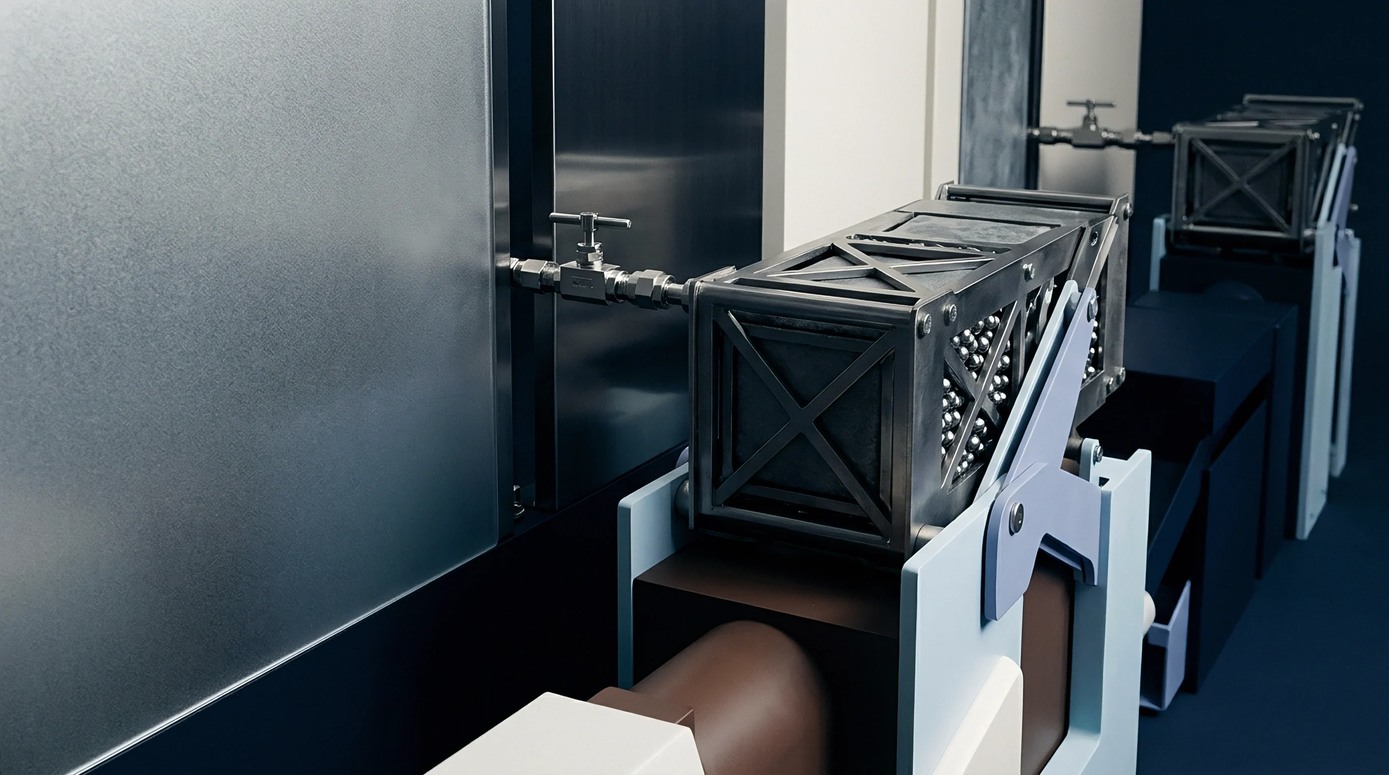
Vapor-phase granular activated carbon (GAC) systems provide reliable adsorption for moderate solvent concentrations. GAC beds use virgin, steam-activated bituminous coal or coconut shell media with internal surface areas exceeding 1,000 square meters per gram. Solvent molecules diffuse into the activated carbon pore matrix, adhering through physical van der Waals forces.
Adsorption dynamics depend on contaminant concentrations, operational temperatures, and gas stream humidity. Relative humidity levels exceeding 65 percent severely degrade carbon adsorption performance. Water molecules compete directly with chlorinated molecules for active carbon pore sites, reducing solvent retention by 50 to 80 percent.
Installing inline air heaters or condensation chillers immediately upstream of the carbon vessels drops relative humidity below 50 percent, stabilizing media life.
Carbon vessel arrays use dual adsorption beds connected in a series lead-lag configuration. The primary lead vessel adsorbs the incoming sub-slab contaminant load. An intermediate sampling port between the lead and lag vessels allows technicians to monitor the mass transfer zone through periodic photoionization detector measurements or laboratory-analyzed gas collection tubes.
Once the lead bed reaches saturation, solvent breakthrough occurs, and the effluent concentration out of the lead vessel rises. The downstream lag vessel captures this migrating breakthrough front, preventing unpermitted environmental releases. Technicians then take the saturated lead vessel offline, advance the clean lag vessel into the lead position, and install fresh carbon into the offline tank.
This operational rotation maintains 100 percent system uptime during hazardous carbon replacement cycles.
Industrial brownfield sites contaminated with complex, high-concentration solvent and petroleum mixtures require alternate abatement technologies based on mass loading:
- Vapor-phase granular activated carbon remains cost-effective for stable low-to-medium contaminant mass rates below 1.5 kilograms per day, offering minimal mechanical infrastructure and reliable field deployment.
- Catalytic oxidizers use precious metal catalysts (platinum or palladium) to combust volatile hydrocarbons at lower temperatures between 300 and 450 degrees Celsius. Catalytic systems handle petroleum fuels efficiently, but chlorinated solvent destruction generates hydrochlorinated acid gas, which destroys standard catalysts and demands acid gas scrubbers.
- Thermal recuperative oxidizers operate at high temperatures between 750 and 1,000 degrees Celsius to thermally destroy high-concentration solvent streams exceeding 10 kilograms per day. High capital expense and intensive auxiliary fuel consumption restrict thermal units to massive, short-term turnover remediation projects.
- Biofiltration beds deploy immobilized damp microbial biofilms to degrade organic vapors into carbon dioxide and water vapor under steady, low-velocity flow rates. Biofilters require significant square footage footprints, struggle with chlorinated aliphatic resistance, and demand continuous biological monitoring.
Permit-by-rule thresholds determine whether an active sub-slab depressurization installation requires comprehensive Title V air operating permits or qualifies for streamlined minor source exemptions. Air permitting authorities evaluate continuous mass emission rates calculated directly from effluent concentration data and extraction blower air throughput:
E = (C Q MW 60) / (V_m 10^6)
In this equation, E represents mass emission rate in kilograms per hour, C represents contaminant gas concentration in parts per million by volume (ppmv), Q represents the total blower volumetric exhaust flow rate in cubic meters per minute, MW represents the chemical molecular weight of the target contaminant (such as 131.39 grams per mole for trichloroethylene), and V_m represents the ideal gas molar volume (0.02445 cubic meters per mole at 25 degrees Celsius and 1 atmosphere). Calculating accurate initial mass emission loading ensures the turnover project remains in full environmental compliance during aggressive initial sub-slab extraction clearing phases.
Calculations showing contaminant mass removal rates falling below local air authority limits permit the systematic bypassing of carbon beds, lowering recurring operations expenses.
Drift
Designing active sub-slab depressurization systems requires managing ambient environmental fluctuations, seasonal atmospheric disruptions, and interior mechanical pressure dynamics. Sub-slab depressurization systems do not operate in a steady-state, static vacuum environment. A turnover facility experiences continuous, dynamic pressure shifts across the floor deck driven by three distinct external forces:
- Barometric pumping caused by the transit of rapid atmospheric weather fronts, where falling outdoor pressures draw sub-slab vapors upward while rapidly rising high-pressure systems push building air downward.
- Building thermal stack effects, where heated interior air rises and exits through upper roof vents during cold winter months, creating a continuous negative pressure zone along the interior ground floor that fights sub-slab vacuum fields.
- Mechanical HVAC ventilation imbalances, where powerful roof exhaust hoods, spray booths, and building air systems pull continuous internal vacuums reaching 5 to 25 pascals relative to the outdoor atmosphere, completely reversing sub-slab negative pressure deltas.
Transient differential pressure inversions degrade system containment. If an industrial ventilation hood pulls 15 pascals of indoor negative pressure while the sub-slab depressurization field provides only 5 pascals of sub-slab suction, the floor slab pressure gradient completely reverses. Sub-slab solvent vapors will flow upward through minor concrete fractures directly into the worker breathing environment, despite continuous blower operation.
Addressing mechanical ventilation competition requires structural depressurization setpoint adjustments, elevating continuous sub-slab vacuum targets to 20 to 35 pascals below interior ambient room pressure throughout active manufacturing production shifts.
How Does Groundwater Fluctuation Compromise Sub-Slab Vacuum Fields?
Groundwater table elevation shifts directly dictate sub-slab gravel pneumatic continuity across coastal or river-valley industrial properties. Heavy seasonal rainfall, spring thaw cycles, or nearby river cresting can elevate localized water tables by 0.5 to 2.0 meters, fully submerging low-lying gravel beds and sub-slab suction cavities. Liquid water filling sub-slab aggregate voids collapses intrinsic pneumatic permeability to absolute zero, halting sub-slab pressure propagation.
Blower vacuum rises sharply as extraction points pull against waterlogged soils, while total air mass flow drops off dramatically. Liquid water enters overhead conveyance manifolds, flooding knockout pots and triggering automated high-level float shutdowns across the central plant.
Mitigating fluctuating groundwater tables requires the installation of dual-phase extraction modifications or localized sub-slab perimeter dewatering networks. Perforated high-density polyethylene drain tiles placed within deep perimeter gravel trenches intercept rising shallow groundwater before the water table reaches the horizontal sub-slab gravel pack. Installing sump pumps maintains the water table at least 0.3 meters below the underside of the floor slab throughout high precipitation seasons, keeping the aggregate open for uninterrupted vapor conveyance.
Low-profile horizontal extraction geovapor membranes placed directly beneath freshly poured floor sections can also elevate the active vacuum zone above high historical groundwater levels.
Frost heave cycles create severe operational challenges in cold climates. High-moisture sub-slab soils freeze during winter along unheated exterior warehouse dock doors and foundation grade walls. Freezing moisture expands, cracking concrete floor slabs and shearing uninsulated subsurface PVC extraction risers.
Sub-slab vapors migrate through newly formed frost cracks. Exterior discharge stacks experience localized internal condensation freezing, where water vapor freezes along cold pipe walls to create ice plugs that constrict blower exhaust. Installing exterior heat tracing, closed-cell elastomeric insulation jackets, and automated condensate drain loops on exhaust stacks preserves continuous clearance operations throughout winter freeze conditions.
System reliability over a multi-year turnover lease demands continuous differential pressure telemetry rather than sporadic annual manual testing. Installing differential pressure transmitters with integrated cellular modems across critical perimeter wings provides automated, round-the-clock verification. These digital sensor arrays log slab pressure deltas at 15-minute intervals, instantly alerting operations directors via automated alerts if building HVAC changes or weather fronts push differential pressure below target regulatory baselines.
Continuous data capture builds an auditable, legally defensible operations record that guarantees environmental health and safety compliance for building occupants and financial stakeholders.
Building managers frequently discover that facility indoor air quality complaints trace back to unbalanced roof exhaust fans overpowering sub-slab depressurization systems during third-shift operations.