Cross Web Wet Film Caliper Tuning through Lip Gap Deflection Control
Cross web wet film caliper tuning requires mechanical gap leveling before closed-loop thermal or piezoelectric actuators can correct dynamic pressure deflection.
Beam
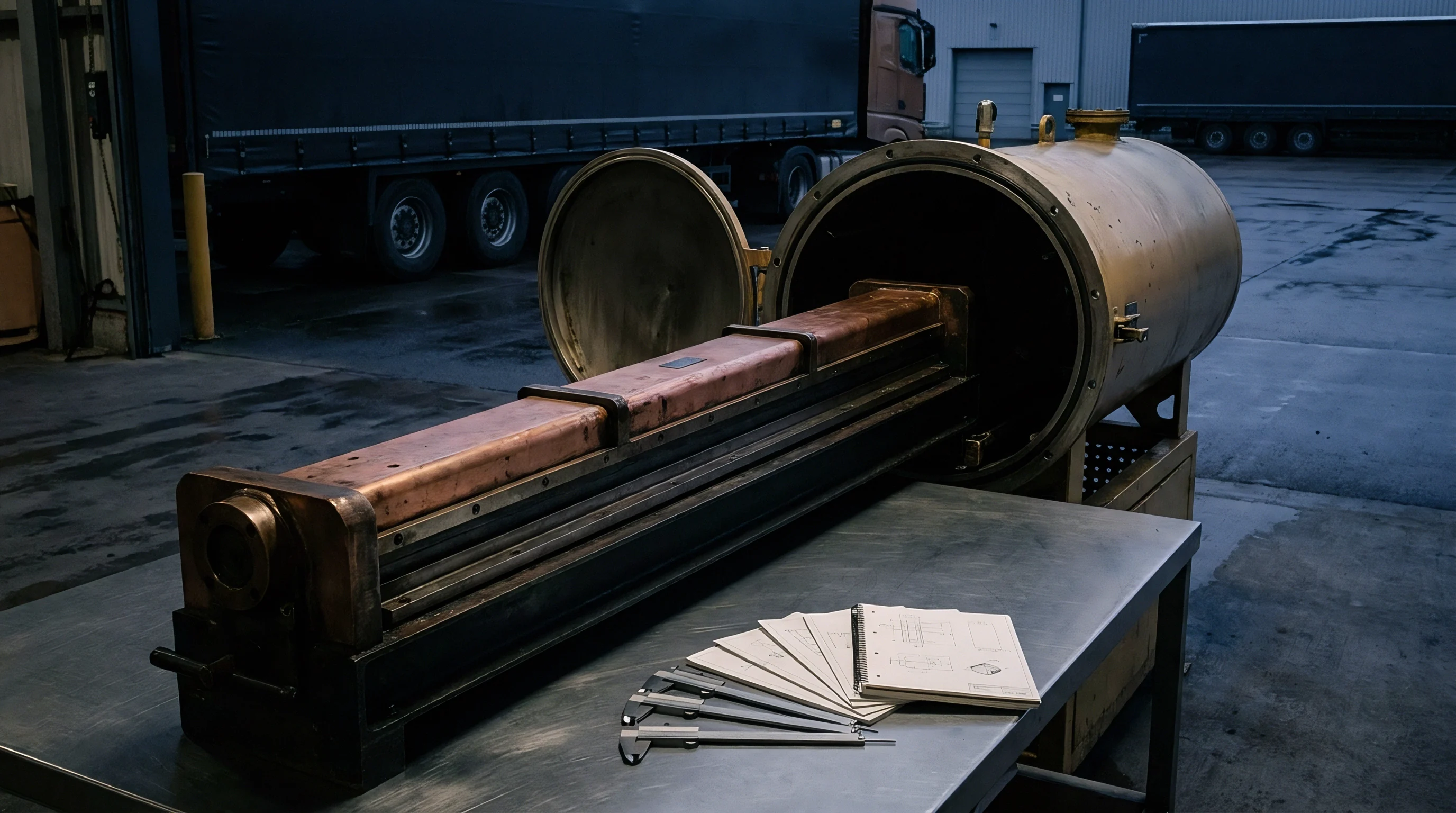
Internal fluid cavity pressures exceeding two bar within an operating slot die push opposing body halves apart along the transverse axis. The resulting displacement distorts the exit orifice before fluid reaches the moving substrate. In viscous laminar flow regimes, volumetric flow through a uniform channel scales with the cube of the slot clearance.
A physical gap widening of two micrometers across a nominal fifty-micrometer exit creates a twelve percent localized surge in wet layer mass. Fluid pressure pushes outward. Viscous drag alters the profile.
The center gap opens wider. Because slot die bodies possess finite elastic modulus, internal hydrostatic pressure turns the lip assembly into a structural member undergoing flexural bending.
Deflection follows the fourth power. For a die lip acting as an elastic beam subjected to uniform internal cavity pressure, maximum mechanical strain concentrates at the midpoint between the body tie bolts. Standard carbon steel or precipitation-hardened stainless alloys deform elastically under production pressures required for high-solids battery slurries or optical polymers.
When fluid viscosity climbs above two thousand centipoise, pressure upstream of the metering land elevates rapidly. The mechanical separation between the upper and lower lip lands assumes an uncontrolled parabolic profile.
Deflection across an unsupported die body concentrates at the manifold center whenever fluid viscosity forces cavity pressures above ambient line resistance.
Internal pressure profiles along the distribution manifold drop from the center inlet toward the end plates. Fluid entering through a single central feed port generates a localized pressure crest directly above the entry channel. Dual-cavity dies distribute this mechanical load across an internal metering land, yet secondary chambers introduce additional internal surface area against which hydrostatic forces react.
Total separating force equals the integrated internal pressure multiplied by the projected horizontal area of the cavity. On an eight-hundred-millimeter coating line operating at three bar cavity pressure, this separating load exceeds twenty-four kilonewtons. Die lip fabricators routinely argue that baseline mechanical distortion remains within specified process limits until plant personnel introduce coating formulations with solids fractions above certified bench trials.
Shim
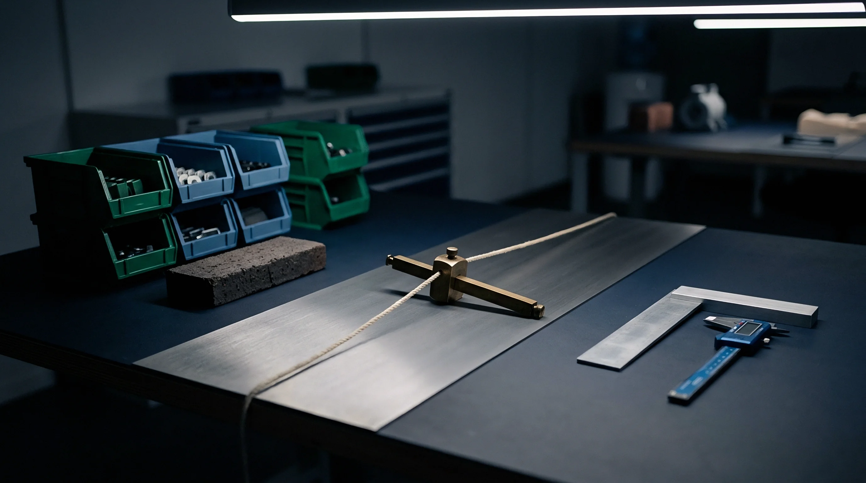
Fixed stainless steel or brass spacing elements positioned between die halves establish the gross geometric boundary before fluid delivery starts. Precision-ground perimeter shims dictate initial cross-web channel depth, defining both slot resistance and baseline velocity profiles across the substrate width. When mechanical tolerances on perimeter spacers vary by more than one micrometer, transverse fluid delivery exhibits permanent striations that active control systems struggle to eliminate.
Slurry viscosity governs internal resistance. Operators reject unverified baseline profiles.
Die body closure bolts generate compressive clamping loads that flatten perimeter spacers against ground land surfaces. Uneven torque application along the bolt line introduces localized mechanical pinching that mirrors the spacing of the individual fasteners. Modern die maintenance calls for calibrated torque sequences beginning at the die center and moving symmetrically outward in three distinct percentage increments.
Skipping these torque stages leaves residual elastic waviness along the front lip edge.
| Web Span (mm) | Die Body Depth (mm) | Cavity Pressure (bar) | Center Deflection (µm) | Wet Caliper Error (%) |
|---|---|---|---|---|
| 400 | 120 | 1.5 | 0.8 | 4.8 |
| 650 | 150 | 2.0 | 1.6 | 9.7 |
| 1000 | 180 | 2.5 | 2.9 | 17.6 |
| 1400 | 220 | 3.0 | 4.4 | 26.8 |
Wear patterns on hardened land faces alter fluid acceleration at the exit corner. Abrasive mineral fillers, ceramic battery particles, and metallic flakes erode the sharp land transitions within three hundred production hours. This progressive abrasive wear increases the effective gap height at the coater edges while leaving central zones restricted by fluid drag, compounding mechanical bowing with surface erosion.
- Torque relaxation reduces clamp force when structural tie bolts lose pre-load under thermal cycling across twenty consecutive coating campaigns.
- Contaminant entrapment generates localized clearance anomalies along the rear sealing gasket and elevates fluid velocity at adjacent feed zones.
- Land surface yielding deforms the precision ground reference edge through over-torquing during aggressive mechanical attempts to force wet caliper compliance.
Neglecting structural clamp balances produces permanent cross-web thickness ridges that trigger complete reel rejections at downstream slitting operations.

Actuation
Mechanical flexure of an upper die lip relies on an array of active push-pull stations positioned across the transverse axis. The flexible lip connects to the rigid die body through a thin machined hinge section, allowing micro-positioning elements to bend the lip locally without permanently yielding the alloy. Spacing between adjuster stations determines the spatial resolution of thickness corrections.
Standard industrial slot dies incorporate adjuster centers spaced between twenty and twenty-five millimeters apart. Thermal expansion bolts demand settling time. Cartridges cycle continuously under PID loops.
Thermal bleed limits spatial independence.
Thermal Expansion Bolt Thermal Crosstalk Limits
Electrically heated adjustment bolts utilize predictable thermal expansion coefficients to drive mechanical displacement against captive thrust blocks. Applying electrical current to a cartridge heater warms an alloy bolt shaft, extending its length by fractions of a millimeter. For a hundred-millimeter bolt constructed from beryllium copper, a temperature elevation of twenty degrees Celsius yields approximately thirty-four micrometers of linear thrust.
Cooling relies on convective ambient airflow or integrated cooling air jackets, making lip opening significantly slower than lip narrowing.
Heat conduction across neighboring adjuster blocks introduces transverse thermal crosstalk. Activating a single thermal bolt to suppress a high-caliper streak inevitably warms adjacent adjustment stations. This lateral conductive bleed widens the effective correction zone, forcing adjacent controllers to lower their power setpoints to compensate.
The thermal gradient broadens across seventy-five millimeters of transverse width, preventing isolated single-point corrections.
Thermal expansion adjusters spaced at twenty-five millimeter intervals introduce a thirty percent mechanical coupling factor into adjacent adjustment zones during steady operation.
Can Closed Loop Actuators Suppress Caliper Ripple?
Piezoelectric micro-actuators deliver instantaneous stroke adjustments under variable direct current voltages. Solid-state piezo stacks respond in milliseconds, generating mechanical push forces exceeding three kilonewtons per station. This immediate mechanical response counteracts rapid fluid pulsation caused by positive displacement feed pumps.
However, total available stroke remains confined to fifteen to twenty micrometers, limiting their use to fine trimming above an accurately ground mechanical baseline.
- Preheating structural die blocks establishes thermal equilibrium across all body components before operators measure initial mechanical clearances.
- Centering adjustment cartridges at fifty percent nominal electrical power reserves bidirectional mechanical stroke for subsequent transverse corrections.
- Executing incremental offsets below two micrometers preserves the elastic operational envelope of the flexible metal hinge.
- Observing thermal settling across fifteen minutes prevents destructive control hunting cycles between adjacent heating elements.

Are Differential Screws Adequate for High Viscosity Pastes?
Manual differential screw adjusters offer rigid mechanical holding power without continuous energy input. Fine pitch threads provide adjustment resolutions down to one-half micrometer per dial division. These rigid mechanical rods resist high separating pressures without deflection, maintaining fixed slot geometries under pulsing hydraulic feeds.
Manual adjusters fail to track dynamic thermal shifts that occur across multi-hour production shifts, demanding manual intervention whenever line speeds change.
Whether solid-state piezo actuators can withstand six continuous months of abrasive slurry backpressures without suffering internal ceramic shear failure remains an unresolved dispute among machinery builders.
Metrology
Online film thickness instrumentation provides the feedback data stream required to run closed-loop profile tuning. Non-contact sensors traverse the moving web downstream of the coating station, recording mass per unit area or physical wet layer depth. The sensor head moves continuously.
Gamma backscatter measures mass directly. Dead time compromises rapid feedback. Downstream tracking introduces significant lag.
Substrate variations complicate optical readings.
Downstream Sensor Latency and Spatial Filtering
Physical separation between the slot die exit and the scanning gauge introduces unavoidable transport delay into the control loop. On a line moving at thirty meters per minute with a scanning head situated fifteen meters downstream, thirty seconds elapse before an adjustment at the die lip appears in the sensor data. Traversing scanner heads take twenty to sixty seconds to complete a single cross-web pass, converting spatial thickness profiles into a temporal measurement sequence.
The resulting control system operates on delayed, diagonally sampled information.
| Measurement Technology | Measurement Target | Sampling Rate (Hz) | Spatial Spot Size (mm) | Calibration Drift (hr) |
|---|---|---|---|---|
| Beta Transmission | Total Mass Basis Weight | 10 | 15.0 | 120 |
| X-Ray Fluorescence | Specific Element Mass | 50 | 5.0 | 250 |
| Confocal Chromatic | True Wet Film Topography | 1000 | 0.05 | 24 |
| Low-Coherence Optical | Wet Layer Optical Thickness | 500 | 0.2 | 48 |
Fourier filtering algorithms separate cross-web caliper variations from machine-direction process ripples caused by feed pump gear meshing. When software maps a scanned thickness trace back to specific die lip actuator zones, spatial misregistration causes the control loop to command the wrong adjuster bolt. Registering web edges accurately against die position markers ensures each thermal zone acts on its matching fluid lane.
A scanner positioned twenty meters downstream from the coating bead observes thickness errors only after several hundred meters of web have passed through the drying tunnel.

Mapping Wet Caliper to Dry Mass Profiles
Non-uniform drying rates across drying enclosures distort the correlation between wet film gap tuning and final dry product thickness. Differential air nozzle velocities strip solvent faster at web edges, causing localized Marangoni migration that pulls fluid toward the perimeter. Active lip gap tuning compensates for this drying phenomenon by intentionally extruding a non-uniform wet profile to produce a flat dry mass distribution.
- Traverse speed logs record synchronized scanner positional encoding across the total coated product width.
- Absorption reference curves track detector signal linearity across shifting solvent and polymer concentrations.
- Edge registration charts confirm that transverse measurement lanes align with their assigned physical die bolt centers.
Paragraph 6.3 of standard delivery agreements establishes that cross-web caliper tuning guarantees apply solely when line speeds and slurry delivery temperatures remain within two percent of qualified steady-state conditions.

Yield
Substrate and raw coating material consumed during actuator stabilization directly dictate startup scrap expenses. In continuous battery electrode manufacturing or high-grade barrier film lines, substrate rolls cost tens of thousands of dollars per single production run. Scrap accumulates during thermal ramp.
Uncalibrated lips destroy coater productivity.
Scrap Generation during Thermal Ramp Stabilization
Thermal expansion actuators take twenty to thirty minutes to achieve thermal equilibrium following a setpoint step command. During this thermal transit period, wet layer thickness drifts outside commercial specification boundaries across twenty to forty percent of the web width. On an electrode coating line operating at sixty meters per minute with an input material value of twenty-five dollars per linear meter, twenty-five minutes of actuator settling generates thirty-seven thousand five hundred dollars in unsalvageable scrap.
Lines lacking baseline mechanical precision generate excessive scrap during every product changeover.
Assume an operation runs a twelve-hundred-millimeter web width at forty-five meters per minute with an active slurry coating cost of fourteen dollars per square meter. A baseline mechanical die lip deflection of four micrometers forces the closed-loop system to drive multiple thermal bolts to maximum heating capacity, inducing severe lateral thermal bleed across adjacent zones. Tuning convergence extends from fifteen minutes to forty minutes per campaign start.
The line consumes twenty-two thousand six hundred and eighty dollars in degraded roll stock before delivering compliant output.
Staged Commissioning Gates for Profile Tuning
Establishing stable cross-web wet film profiles follows a strict progression of stage-gated operational steps. Operators must not apply electrical power to thermal bolts or engage closed-loop automation while the underlying mechanical die geometry remains out of true. Pre-commissioning begins with offline profilometry of cold die lips, verifying parallelism across the entire transverse span within one micrometer using precision dial indicators.
The sequence progresses to heated fluid circulation at operational temperatures without substrate movement, establishing baseline hydraulic pressures inside the internal cavities. Only after offline metrology confirms zero-pressure lip straightness and steady fluid temperatures do operators initiate web transport and engage closed-loop thickness scanning. Attempting to compensate for mechanical lip damage or uneven body torque through aggressive closed-loop thermal tuning causes actuator saturation, leaving zero control margin for dynamic process shifts.
Coating lines achieve cross web stability faster when mechanical lip gap alignment precedes thermal bolt activation.